hugh.radkins@LIGO.ORG - posted 10:32, Monday 25 November 2013 (8713)
WBSC10 HEPI Actuators in Run Mode
Transitioned the ETMy HEPI Actuators to Run mode. We are ready.
Transitioned the ETMy HEPI Actuators to Run mode. We are ready.
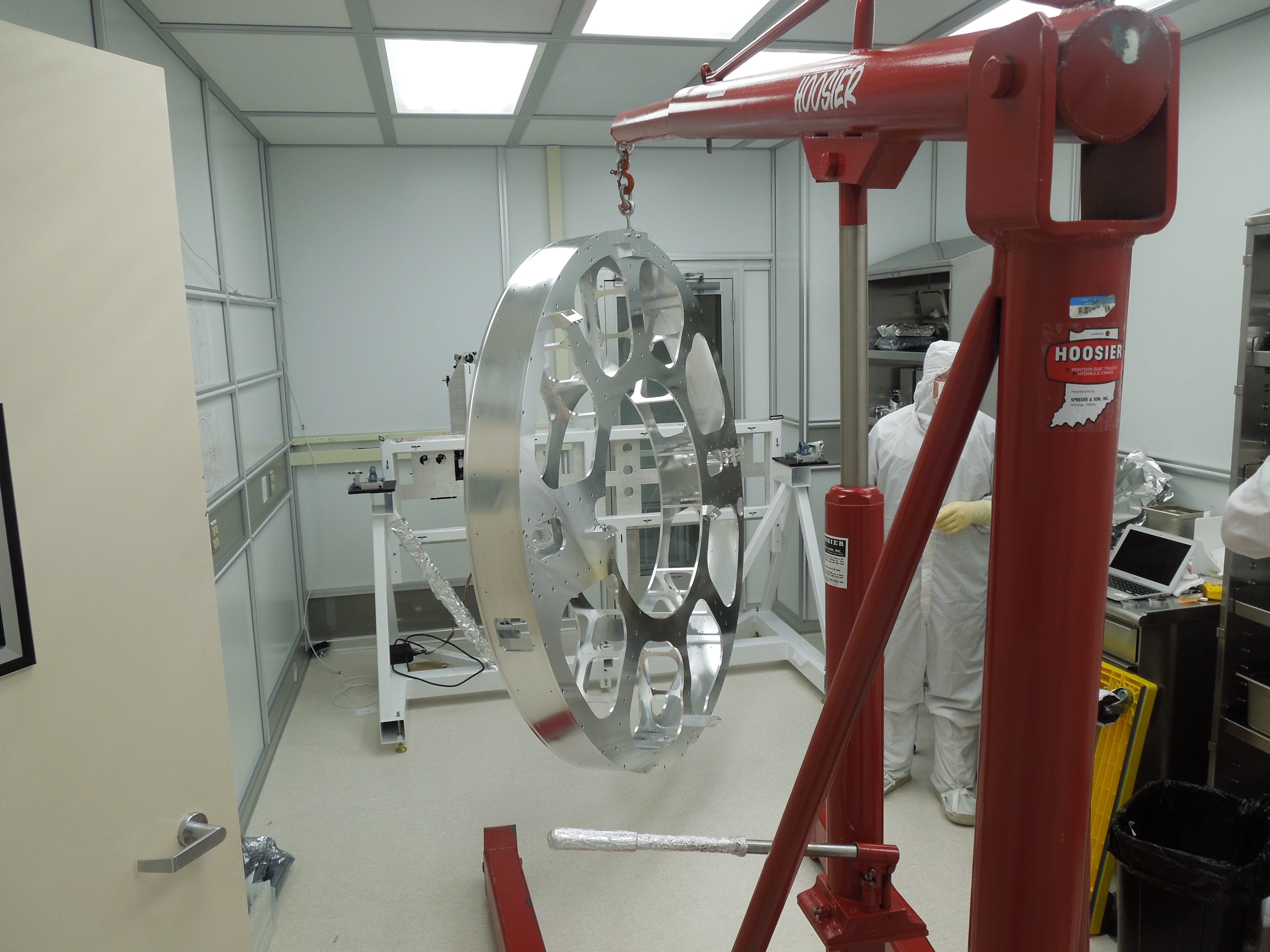
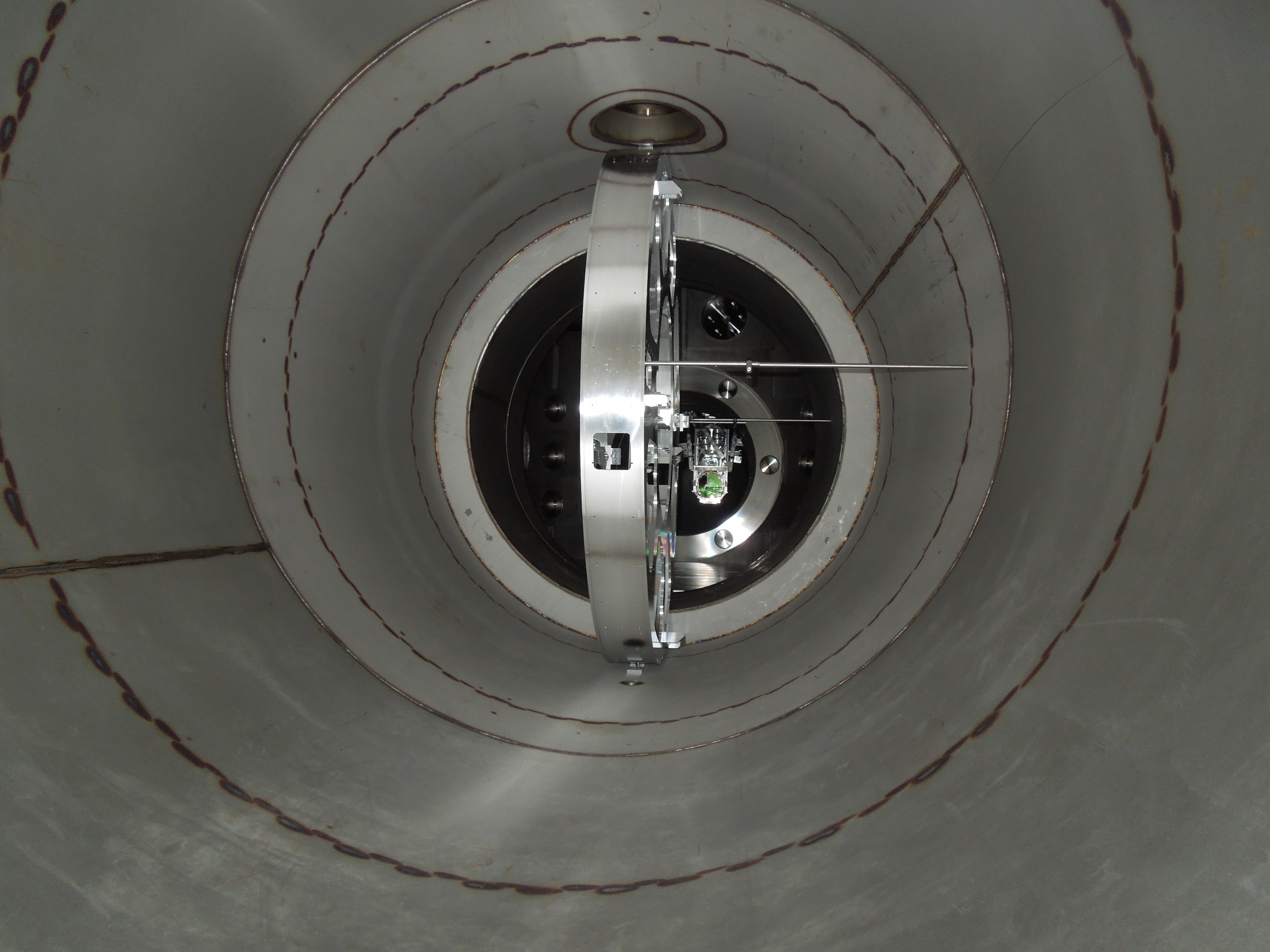
Mike V, Gerardo M, and Mitchell R

Saturday we were able to complete the primary baffle assembly and transferred to the balancing fixture. Current steps now are to complete the balancing process and transfer assembly back to the installation fixture. This should be completed by mid-late afternoon today. This would ideally mean that the Cryobaffle assembly will be ready for install Tuesday.
J. Kissel

I'm slowly working my way through the 14 suspensions that need chamber close-out testing after last week's furiously awesome effort to get doors on before the Thanksgiving week. It's going slower than expected because, for some of the SUS, I'm taking "Official SUS-style" TFs for the first time at LHO, so I've gotta tweak the measurements, make sure the SUS are set up correctly, and also because -- even on a Saturday! -- I'm interrupted with people calling me ask work questions ( THANKS JANEEN, GOSH (-; ). Anyways, enough whining. So far, I've seen no signs of badness -- excellent! Details below, and plots proving the goodness to come later.

----

I've now got and exported the (DTT) data for all degrees of freedom of M1 to M1 TFs
TMSX, RM1, and RM2
and they've been committed to the SVN. I'll process the data later when I find out from my colleagues in what the state of the matlab analysis software lies for these orphaned SUS types that we're now re-adopting into the family.

I still need to get M1 to M1 TFs of
IM1, IM2, IM3, IM4, MC1, MC2, MC3, PRM, PR2, PR3
and both M0 to M0 and R0 to R0 TFs for
ITMX

I've created new directories in the SUS repo for the HTTS, which hadn't been created yet for LHO because no one had taken any data on them.
The templates for the data I've taken are here:

/ligo/svncommon/SusSVN/sus/trunk/HTTS/H1/RM1/SAGM1/Data/
2013-11-23_2120_H1ASCRM1_M1_WhiteNoise_L_0p1to50Hz.xml
2013-11-23_2120_H1ASCRM1_M1_WhiteNoise_P_0p1to50Hz.xml
2013-11-23_2120_H1ASCRM1_M1_WhiteNoise_Y_0p1to50Hz.xml

/ligo/svncommon/SusSVN/sus/trunk/HTTS/H1/RM1/SAGM1/Data/
2013-11-23_2214_H1ASCRM2_M1_WhiteNoise_L_0p1to50Hz.xml
2013-11-23_2214_H1ASCRM2_M1_WhiteNoise_P_0p1to50Hz.xml
2013-11-23_2214_H1ASCRM2_M1_WhiteNoise_Y_0p1to50Hz.xml

/ligo/svncommon/SusSVN/sus/trunk/TMTS/H1/TMSX/SAGM1/Data/
2013-11-23_2045_H1SUSTMSX_M1_WhiteNoise_L_0p1to50Hz.xml
2013-11-23_2045_H1SUSTMSX_M1_WhiteNoise_P_0p1to50Hz.xml
2013-11-23_2045_H1SUSTMSX_M1_WhiteNoise_R_0p1to50Hz.xml
2013-11-23_2045_H1SUSTMSX_M1_WhiteNoise_T_0p1to50Hz.xml
2013-11-23_2045_H1SUSTMSX_M1_WhiteNoise_V_0p1to50Hz.xml
2013-11-23_2045_H1SUSTMSX_M1_WhiteNoise_Y_0p1to50Hz.xml

For each, I've exported both as .pdf and .txt with the same name (_tf tag for transfer function, _coh for coherence) for use later.

The triples and QUAD should go much quicker since there are already many measurements of them with known good DTT templates, so it's just a matter of opening them up and hitting go. Why DTT, and not the automated Matlab software that you can just set and forget, you ask? Because over the course of 6 hours, there're too many things that can fail with the automated system at this point, and you don't know of a failure until you've wasted the six hours. I'd rather mindlessly click buttons for six hours with DTT, constantly confirming that things are going well, and listen to some good tunes on a Saturday afternoon.
Craig Conley, Mark Lane, Joe DeRenzis, Chris Soike, Rick Savage

The in-vacuum periscope structure for Yend was pre-aligned in the H2 Laser Area Enclosure.  Mirror mounts were removed and it was wrapped and transported to EndY where it was installed inside the A7 adapter.  It was moved to the staging location where it was rotated 90 deg. to allow access for the Manifold/Cryobaffle installation work.

Tools and installation tooling were left inside the periscope frame in anticipation of its move to the final location after the baffle installation.

Photos attached.
Chris, Kiwamu, Sheila,
I just transitioned the PS to science mode, in the hopes that this will at least simplify troubleshooting the aligment problems we are having if we dont have the 20 minute temperature swings anymore.
Chris has written verry nice scripts that take snapshots of the two transmitted cameras, and calculates the centroid.
The ref cav trans centroid is temporarily plotted as H1:LSC-DARM_OFFSET and H1:LSC-MICH_OFFSET and the PMC trans centroid is saved as H1:LSC-SCRL_OFFSET and H1:LSC-PRCL_OFFSET.
we can use this decide if the cavities themselves are moving.
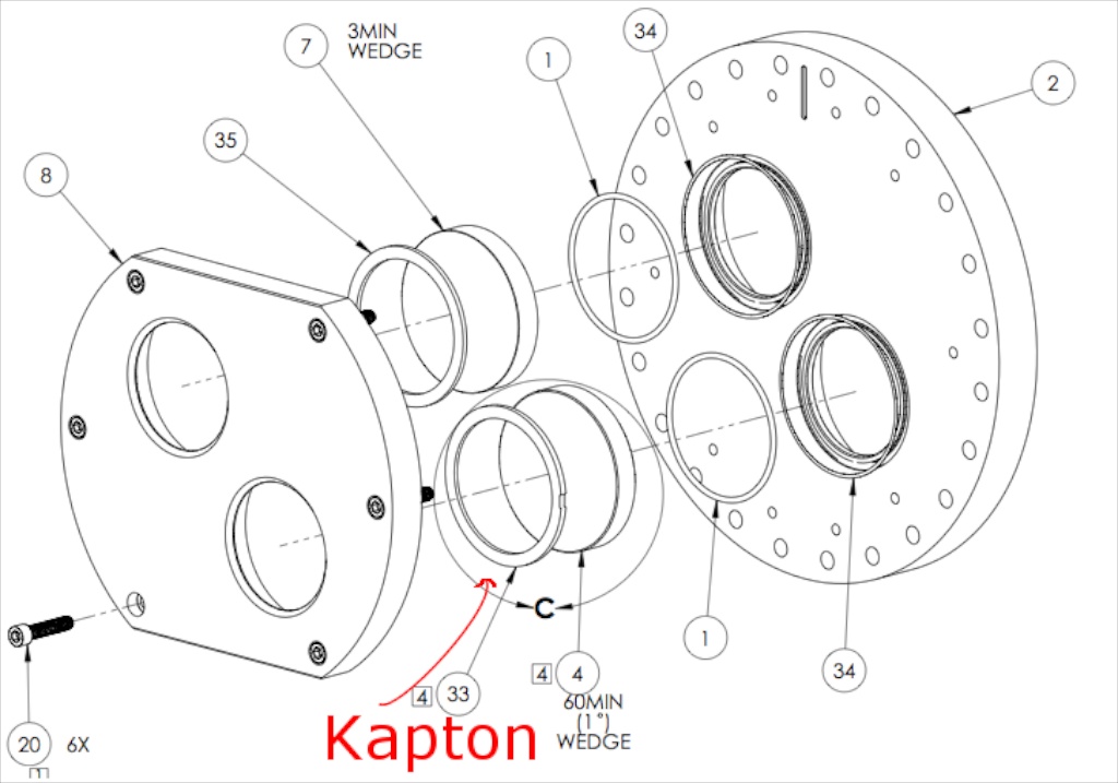
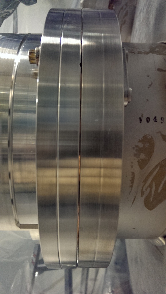
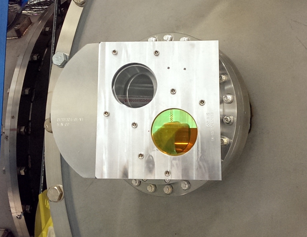
The TCS viewports were installed on BSCs 1 and 3 today. The gap on the optic enclosure for the primary optics was between .030" and .040" on both viewports. So the new Kapton shims created a good gap for pulldown onto the Viton. They were proofed and leak tested Wednesday and Thursday. There was a small issue with the proofing as the Kapton wedge on top of the primary optics doesn't seal (nor is it expected to). So although the pressure for proofing (15.5 psi) was reached it would not hold. This was determined not to be an issue. The leak test went without incident, Helium flow was 1 LPM and each optic was targeted for ~30 seconds and the enclosure was targeted for ~1 - 1.5 minutes. No leaks were seen, calibration using internal leak showed 1.0e-7 torr L/s with a stated value of 9.8e-8 torr L/s.

The viewports replaced the blanks on the chambers today. Kyle noted the gap pre-torquing of the bolts was low and the gap was found to be 0.02". Lower than is normally sought (>0.025"). This seems to be from a deeper recessed knife edge on the viewport. John gave the okay to torque the viewports down and continue. They are now metal to metal on the flange.
Picomotor mistery solved: It was an in-chamber cable. Unlike the ones Corey looked at in the lab today, what we have in chamber is "A"=J5, "D"=J2. See Alexa's alog.
In-chamber alignment done: We adjusted the IR QPD sled. Since we already rotated the 50-50 BS 180 degrees yesterday, there was no way the QPD sled could be left untouched, but anyway when we started it was not that bad, and only a small touch up was necessary.
One thing we did NOT understand is why it was easy to do this this time. If you remember the story from EY installation, the reflectivity of 50-50 IR splitter is almost zero for green S (correct) polarization, and it was almost impossible to find the right beam without using a bad polarization. This time, however, it was easy to see the beam with the beam leaving the table as is, and rotating the polarization 90 degrees made it worse.
Maybe the existence of the first contact on the HR side of ETMX is doing something funny for the polarization, though the transmissivity of HR for green is between 3% and 15% according to witness sample measurement by LIGO and 27% according to LMA (https://dcc.ligo.org/C1103232) so it's not that likely that the FC is doing something significant.
Becoming suspicious if we're using correct optics, we checked the DCC number of 1" IR 50-50 splitter and 1" high reflector, but they were both correct.
Anyway, the important thing is that the green leakage light into IR QPD sled is centered on QPDs when the ETM is retro-reflecting the beam, and we (Kiwamu and I) are quite confident that the beam we're looking at is the correct one.
BOSEMs were checked, they 're not touching, and the centering is not terrible either (though certainly it's not perfect). We set the depth of BOSEMs so the output becomes 15000-ish.
Some tools that are not ours are left in chamber.
What's next:
Pictures here:
https://ligoimages.mit.edu/?c=1396
[Jim, Sebastien]
This week, we've seen the gain of L4C-H2 changing randomly, from nominal gain to a factor of 2 lower.
We tried to chase down this issue without success (see aLOG #8632 and 8666). Everytime we tried something, it magically resolved by itself, and there were no way to reproduced it.
After it happened again today, we might have found the issue though: the in-air cable at the feedthrough felt a little "squishy" and loose. Jim unplugged it and readjusted everything. It feels much better now, and the issue is once again gone.
According to what we saw before, we're pretty confident that was it. If it wasn't, let's keep in mind to start looking at the feedthrough when it happens again.
This is ITMx.
All the HEPI models have been updated, compiled and installed at LHO on all teh HEPIs. The update went great, no issue so far.
The next action monday will be, on HEPI-HAM2 and HEPI-HAM3, to translate the alignment offsets calculated before when the IMC was locked (see aLOG # 7189 and 7180) from local basis to cartesian basis.
Not a hard task, but I've been having trouble with it. I'll continue Monday.
Tfs were run last night but we have a few empty buckets. Filling those overnight. OPSWS0.
Deed was done ~10 am local.
Day Shift Summary
LVEA Laser Safe

Patrick – Changing dust monitoring sample and hold times on several dust monitors
Gerardo – At End-Y
Filiberto – At End-Y working on the Beckhoff system
Jonathan – Recovering equipment from LVEA
Cory – At End-X gathering TMS parts for shipment to LLO
Sebastian – Restarting HEPI models
Hugh – At End-Y working on HEPI
Dave/Jim – Restart the DAC
Dale – At End-Y checking on P-Cal Install
Scrap Metal Recyclers on site to change out collection containers
Cyrus – At Mid-X to swap media converters
I swapped out the DAQ Netgear switch at MX for the appropriate media converter, to reclaim this switch for other purposes. This matches the earlier change for the FE switch for MX/h1pemmx. h1pemmx was restarted successfully.
The H1SUSIM model died at 9:15 AM PST with an error of ADC timeout. The h1susim and h1iopsush2b models were restarted about 10:22 PST to clear the error.
After Sebastien updated the HEPI models I did a DAQ restart to resync the INI files at 11:08
The following cables for the demod concentrator readbacks (HAM6) did not have pin 19 connected as reported by Daniel Sigg https://alog.ligo-wa.caltech.edu/aLOG/index.php?callRep=8640 :

H1:ISC_203
H1:ISC_204
H1:ISC_205
H1:ISC_207
H1:ISC_210

Pin 19 was attached on both ends and reconnected back to electronics.
Temp dogs were removed.
Isctex green periscope readjusted as it was close to the edge.
Tele beam position readjusted so the beam is centered on the primary.
Red extraction path was done.
High power beam dump path was done.
Working on IR QPD sled path.
Picomotor cable mystery.
It seems as if picomotor ordering is flipped somewhere between Beckhoff and in-chamber.
Picomotor in-vac cable has one DB25 (called J1) on one end and four smaller cables with mighty mouse connector (J2, J3, J4 and J5) on the other. In the cable drawing (https://dcc.ligo.org/D1000238) , these four cables are numbered such that the one closest to pin 1 of DB25 is J5, the farthest J2.
Both sites agreed that J2 goes to the green 50-50 splitter (M3), J3 to the steering mirror just upstream of the periscope (M6), J4 to the dichroic that steers the IR to the sled (M4), and J5 to the steering mirror just upstream of the IR sled (M14).
Now, the aluminum collar for the picomotor connectors are labeled as "A", 'B", 'C" and "D", and it's these labels that I and Corey used, assuming that A is J2 and D is J5.
However, in the cable harness routing diagram (https://dcc.ligo.org/LIGO-D1300007), the same cable is specified such that the one closest to pin1 of DB25 is "to M1", the farthest "to M4", it is ordered starting from pin 1 of DB25, so it's the opposite of the cable drawing. So A might be J5 and D J2, and this might be it. If so, we will re-rout the in-vac cables.
I have a vague memory that Corey confirmed that A is the closest to pin1, but I'm not 100% sure.
Since there's no way we can find which cable is closer to pin 1 without disconnecting DB25, and since there's a certain risk to disconnect and reconnect in-vac DB25, I'm asking Rich Abbott if he remembers which convention was used when labeling mighty mouse connectors.
Checking Cable (D1000238) In Lab
I pulled out two random (s/n S1104585 & S1105221) Picomotor cables to check how the four Mighty Mouse connectors are marked & where they are located. On both cables, they are marked in a way which matches the drawing/our guess for EX TMS (but not for Keita's memory for what I confirmed in-chamber in Sept):
I'm re-attaching photo/note of what we saw when we tested the Picomotor cable at the Test Stand next to the BSC (we observed the switched around order back in Sept):
(Alexa, Stefan, Kiwamu, Keita)
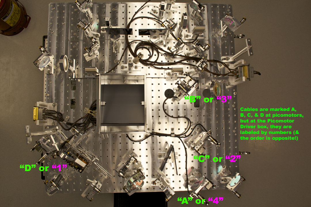
The convention at both LHO and LLO for the picomotor in-vac cables is as follow:
Unfortunately, the in-vac cables in HAM6 had cable "A" = J2 closest to pin 1 and cable "D" = J5 closest to pin 13; however the opposite is desired. This explains the switch. We have swapped the ABCD cables in vacuum, and now the picomotor controls are all correct. Success!
Moral of the story: be careful with the ABCD labellings on the picomotor in-vac cabling because they don't seem to be consistent. It would also be nice to have pin 1 labeled on the outside of the cable connector so that we do not have to disconnect it to know where pin 1 is located.
After fixing any loose dog clamps, and retorquing, Arnaud and I took B&K hammer measurements of the HAM2 PR3, PRM, and MC1 this morning. We still need to do PR2 and MC3 (which has a temp IO alignment mirror nestled up against it's structure). We took PR3 and PRM data with vibration absorbers on and off. We only took MC1 data with the vibration absorbers on since they were already on and are difficult to remove and then replace. Plots and statements to come.
Arnaud and I snuck in and got B&K hammering done on PR2 before the transition to laser hazard.
Betsy and I hammered the last suspension missing in our list: MC3.
The results are coming soon
Results are at alog 6014
LHO aLOG 6014 are different results -- from PR3, and they don't even include the results for that measurement. Arnaud and I will be processing and post all the B&K data from the HAM2, HAM3, and and BSC3 (ITMX) next week.