J. Kissel, B. Weaver, M. Landry, S. Biscans, C. Remet H. Radkins, T. Vo, B. Gateley
*phew*
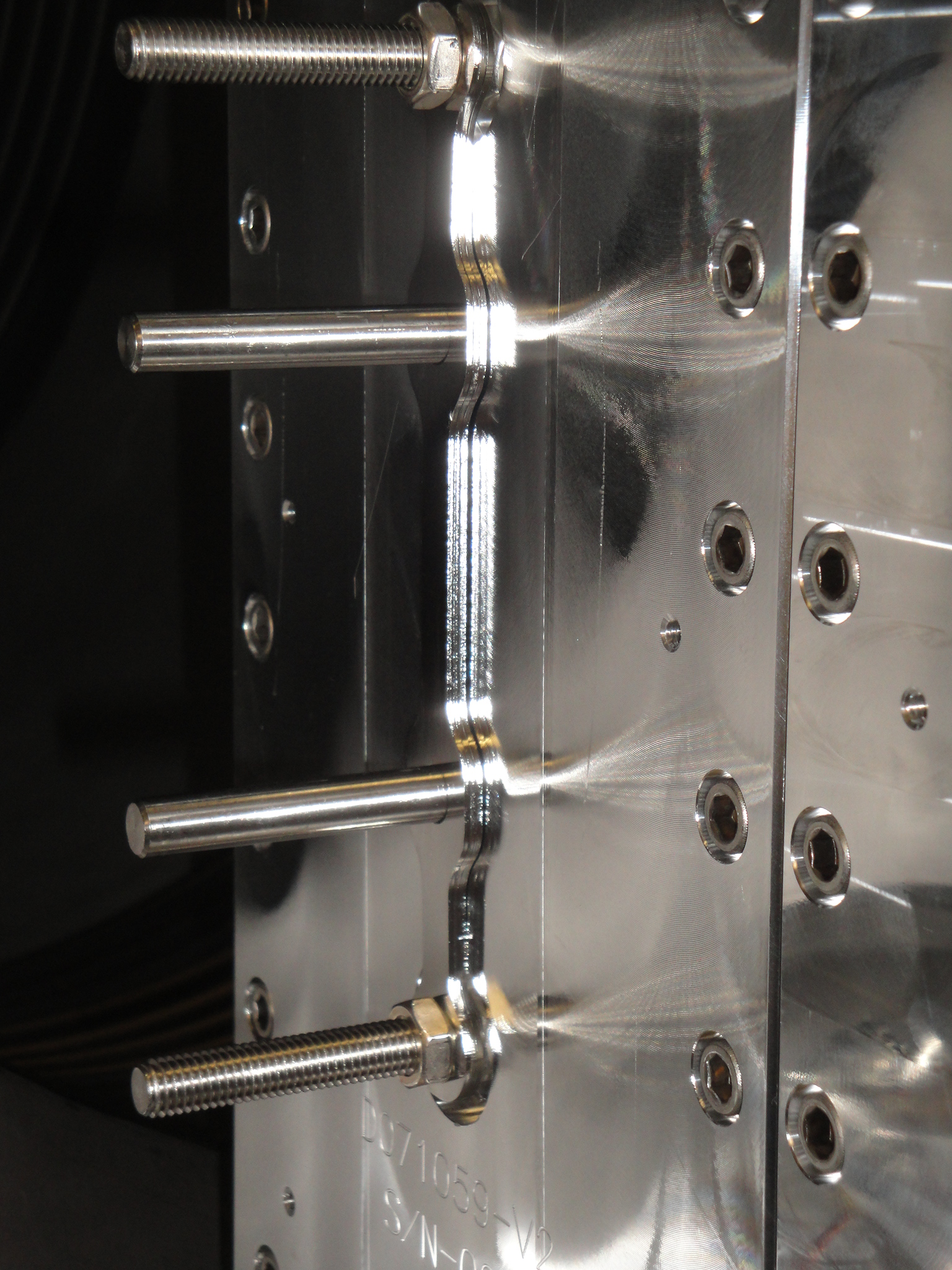
The last known in-chamber payload suspect in the misdemeanor seen earlier with the ISI-ITMX vertical transfer functions was the teflon rails that were temporarily installed on the SUS-ITMX for first-contact cleaning. So, Betsy and I went out and removed them. Preliminary measurements (attached below) indiciate these were the problem, the ISI looks fine now. We are a go for final cleaning and close up of BSC3 (as agreed by all those listed above). In the next half hour that it takes me to finish writing this aLOG, Sebastien is going to get a few more transfer functions just to be sure we're OK, but Celine (from afar) has been watching the story, and has informed us that she had seen similar badness when she had taken ISI transfer functions with the QUAD locked (with EQ stops), so we 100% confident that things have been restored to goodness already.
To repeat for clarity,
- It wasn't the dome installation that caused the badness
- It wasn't the arm cavity baffle's eddy current dampers or mechanical rubbing
- It wasn't the in-chamber cabling
It was 300 kg of mass (the suspended elements of the QUAD) that had been temporarily locked up with teflon rails for the (new, yet) normal first contact routine.
--------
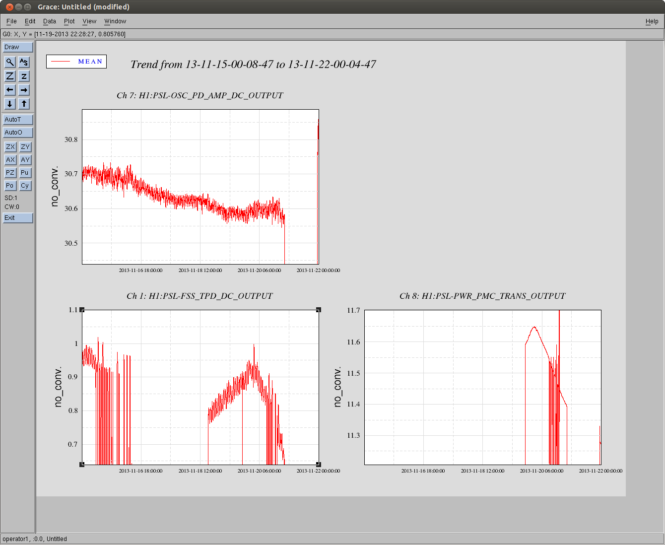
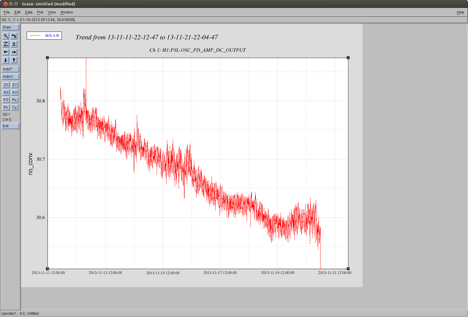
Plot Caption:
[[ISI-ITMX, Stage 0-1 Actuator drive, Stage 1 CPS sensor response, driven transfer function.
HEPI is floating and balanced, ISI is floating and balanced, ISI control is entirely OFF,
ACB is freely suspended and Eddy-current Damped, SUS-ITMX is freely suspended with main
and reaction chain locally damped with top-stage OSEMs]]
BLACK Known good reference measurement taken over Tuesday-to-Wednesday (2013-Nov-19 to 20) night.
BLUE The bad state the ISI has been since measuring quickly Wednesday afternoon, after
Teflon rails are installed,
QUAD is first-contact painted,
ACB is B&K hammered
Dome is installed
ACB is re-inspected
ISI and other in-vac cabling is inspected (from underneath the ISI)
RED Now good, current measurement, after Betsy removed the temporary teflon rails.

Picomotor cable mystery.
It seems as if picomotor ordering is flipped somewhere between Beckhoff and in-chamber.
Picomotor in-vac cable has one DB25 (called J1) on one end and four smaller cables with mighty mouse connector (J2, J3, J4 and J5) on the other. In the cable drawing (https://dcc.ligo.org/D1000238) , these four cables are numbered such that the one closest to pin 1 of DB25 is J5, the farthest J2.
Both sites agreed that J2 goes to the green 50-50 splitter (M3), J3 to the steering mirror just upstream of the periscope (M6), J4 to the dichroic that steers the IR to the sled (M4), and J5 to the steering mirror just upstream of the IR sled (M14).
Now, the aluminum collar for the picomotor connectors are labeled as "A", 'B", 'C" and "D", and it's these labels that I and Corey used, assuming that A is J2 and D is J5.
However, in the cable harness routing diagram (https://dcc.ligo.org/LIGO-D1300007), the same cable is specified such that the one closest to pin1 of DB25 is "to M1", the farthest "to M4", it is ordered starting from pin 1 of DB25, so it's the opposite of the cable drawing. So A might be J5 and D J2, and this might be it. If so, we will re-rout the in-vac cables.
I have a vague memory that Corey confirmed that A is the closest to pin1, but I'm not 100% sure.
Since there's no way we can find which cable is closer to pin 1 without disconnecting DB25, and since there's a certain risk to disconnect and reconnect in-vac DB25, I'm asking Rich Abbott if he remembers which convention was used when labeling mighty mouse connectors.
Checking Cable (D1000238) In Lab
I pulled out two random (s/n S1104585 & S1105221) Picomotor cables to check how the four Mighty Mouse connectors are marked & where they are located. On both cables, they are marked in a way which matches the drawing/our guess for EX TMS (but not for Keita's memory for what I confirmed in-chamber in Sept):
I'm re-attaching photo/note of what we saw when we tested the Picomotor cable at the Test Stand next to the BSC (we observed the switched around order back in Sept):
(Alexa, Stefan, Kiwamu, Keita)
The convention at both LHO and LLO for the picomotor in-vac cables is as follow:
Unfortunately, the in-vac cables in HAM6 had cable "A" = J2 closest to pin 1 and cable "D" = J5 closest to pin 13; however the opposite is desired. This explains the switch. We have swapped the ABCD cables in vacuum, and now the picomotor controls are all correct. Success!
Moral of the story: be careful with the ABCD labellings on the picomotor in-vac cabling because they don't seem to be consistent. It would also be nice to have pin 1 labeled on the outside of the cable connector so that we do not have to disconnect it to know where pin 1 is located.