We have been looking for ways to figure out which SVN revision is in use on the workstations, and which revision is available on the server. The goal is to allow the commissioners to understand where they stand regarding the ongoing updates.
Charles and I came up with the following sequence using svn log. The whole subtlety of it is the use of: ^, which tell the svn log to look at the server, and not the working copy.
Details are shown below, with h1isihammaster.mdl as an example.
Note: There may be a better way to do this. We just thought this one would be good enough for now.
Check What Is Loaded On The Local Copy
controls@ligo-ops2:/opt/rtcds/userapps/release/isi/common/models$ svn log -l 5 isihammaster.mdl
------------------------------------------------------------------------
r5713 | jeffrey.kissel@LIGO.ORG | 2013-09-16 15:41:18 -0700 (Mon, 16 Sep 2013) | 1 line
committing new master models for HAM and BSC. include changes for science frame channels, ODC gain monitoring, and migraion of checker-script to the front end - not yet tested at LASTI
------------------------------------------------------------------------
r5044 | hugo.paris@LIGO.ORG | 2013-07-19 14:28:17 -0700 (Fri, 19 Jul 2013) | 1 line
New ISI models including Cart biases.
------------------------------------------------------------------------
r4978 | celine.ramet@LIGO.ORG | 2013-07-12 10:37:53 -0700 (Fri, 12 Jul 2013) | 1 line
new ham-isi master model adding the recording of the sens corr channels
------------------------------------------------------------------------
r4677 | hugo.paris@LIGO.ORG | 2013-06-10 15:20:27 -0700 (Mon, 10 Jun 2013) | 1 line
corrected typo on the BLRMS links of ISISTAGE/SENSCOR/, in coordinaation with LLO (CR)
------------------------------------------------------------------------
r4659 | celine.ramet@LIGO.ORG | 2013-06-07 10:33:26 -0700 (Fri, 07 Jun 2013) | 1 line
isihammaster mod to allow L4C or STS sensor correction-CR
------------------------------------------------------------------------
Check What Is Available On The Server:
controls@ligo-ops2:/opt/rtcds/userapps/release/isi/common/models$ svn log -l 5 ^/trunk/isi/common/models/isihammaster.mdl
------------------------------------------------------------------------
r6061 | stefan.ballmer@LIGO.ORG | 2013-10-25 12:24:57 -0700 (Fri, 25 Oct 2013) | 1 line
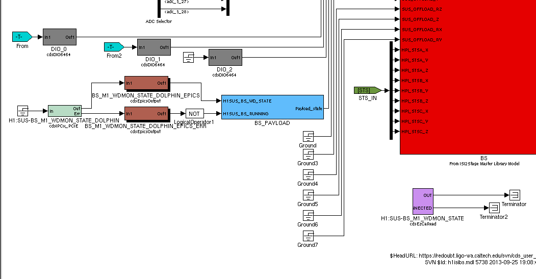
installed 32bit ODC parts for isi2stagemaster.mdl isihammaster.mdl and route signal up to top per ECR E1300740
------------------------------------------------------------------------
r5713 | jeffrey.kissel@LIGO.ORG | 2013-09-16 15:41:18 -0700 (Mon, 16 Sep 2013) | 1 line
committing new master models for HAM and BSC. include changes for science frame channels, ODC gain monitoring, and migraion of checker-script to the front end - not yet tested at LASTI
------------------------------------------------------------------------
r5044 | hugo.paris@LIGO.ORG | 2013-07-19 14:28:17 -0700 (Fri, 19 Jul 2013) | 1 line
New ISI models including Cart biases.
------------------------------------------------------------------------
r4978 | celine.ramet@LIGO.ORG | 2013-07-12 10:37:53 -0700 (Fri, 12 Jul 2013) | 1 line
new ham-isi master model adding the recording of the sens corr channels
------------------------------------------------------------------------
r4677 | hugo.paris@LIGO.ORG | 2013-06-10 15:20:27 -0700 (Mon, 10 Jun 2013) | 1 line
corrected typo on the BLRMS links of ISISTAGE/SENSCOR/, in coordinaation with LLO (CR)
------------------------------------------------------------------------
SVN UP
controls@ligo-ops2:/opt/rtcds/userapps/release/isi/common/models$ svn up isihammaster.mdl
U isihammaster.mdl
Updated to revision 6065
Note: 6065 is the "head revision" number
Check That The Local Copy Is Up To Date (same revision as the one on the server):
controls@ligo-ops2:/opt/rtcds/userapps/release/isi/common/models$ svn log -l 5 isihammaster.mdl
------------------------------------------------------------------------
r6061 | stefan.ballmer@LIGO.ORG | 2013-10-25 12:24:57 -0700 (Fri, 25 Oct 2013) | 1 line
installed 32bit ODC parts for isi2stagemaster.mdl isihammaster.mdl and route signal up to top per ECR E1300740
------------------------------------------------------------------------
r5713 | jeffrey.kissel@LIGO.ORG | 2013-09-16 15:41:18 -0700 (Mon, 16 Sep 2013) | 1 line
committing new master models for HAM and BSC. include changes for science frame channels, ODC gain monitoring, and migraion of checker-script to the front end - not yet tested at LASTI
------------------------------------------------------------------------
r5044 | hugo.paris@LIGO.ORG | 2013-07-19 14:28:17 -0700 (Fri, 19 Jul 2013) | 1 line
New ISI models including Cart biases.
------------------------------------------------------------------------
r4978 | celine.ramet@LIGO.ORG | 2013-07-12 10:37:53 -0700 (Fri, 12 Jul 2013) | 1 line
new ham-isi master model adding the recording of the sens corr channels
------------------------------------------------------------------------
r4677 | hugo.paris@LIGO.ORG | 2013-06-10 15:20:27 -0700 (Mon, 10 Jun 2013) | 1 line
corrected typo on the BLRMS links of ISISTAGE/SENSCOR/, in coordinaation with LLO (CR)
------------------------------------------------------------------------