During the red beam lock, the 2 HEPIs and ISIs (BSC1 and BSC6) were supposedly in the state given by alog https://alog.ligo-wa.caltech.edu/aLOG/index.php?callRep=7235. By the time, the HEPI at BSC1 was locked. Some information were extracted from the 15-minute lock. ISIs provide great isolation above 100mHz but the motion increase below 100mHz is not negligible and can become problematic to lock the cavity. The results present the ISI’s contribution in the arm’s length variation.
The arm was kept locked using the red beam. The green beam is used as a witness sensor.
1- State of the ISIs
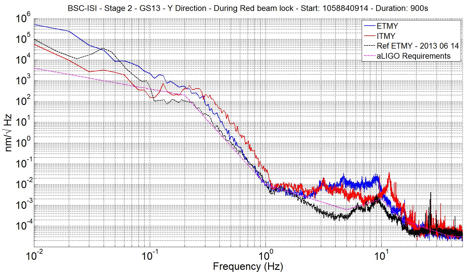
The attached spectra (H1_BSC_ISI_ST2_GS13_Y_20130726.jpg) show the motion of stage 2 in the Y-direction of the 2 BSC-ISIs (ITMY and ETMY) during the lock.
On ITMY (red curve):
- It is not sure if the sensor correction was engaged properly (no amplification at low frequency and no and important motion at 700mHz)
- The resonance of the HEPI pier is clearly visible at 11.5Hz
On ETMY (Blue curve)
- Above 2 Hz, the motion is much larger than on June 14th - Reference in black (same configuration?)
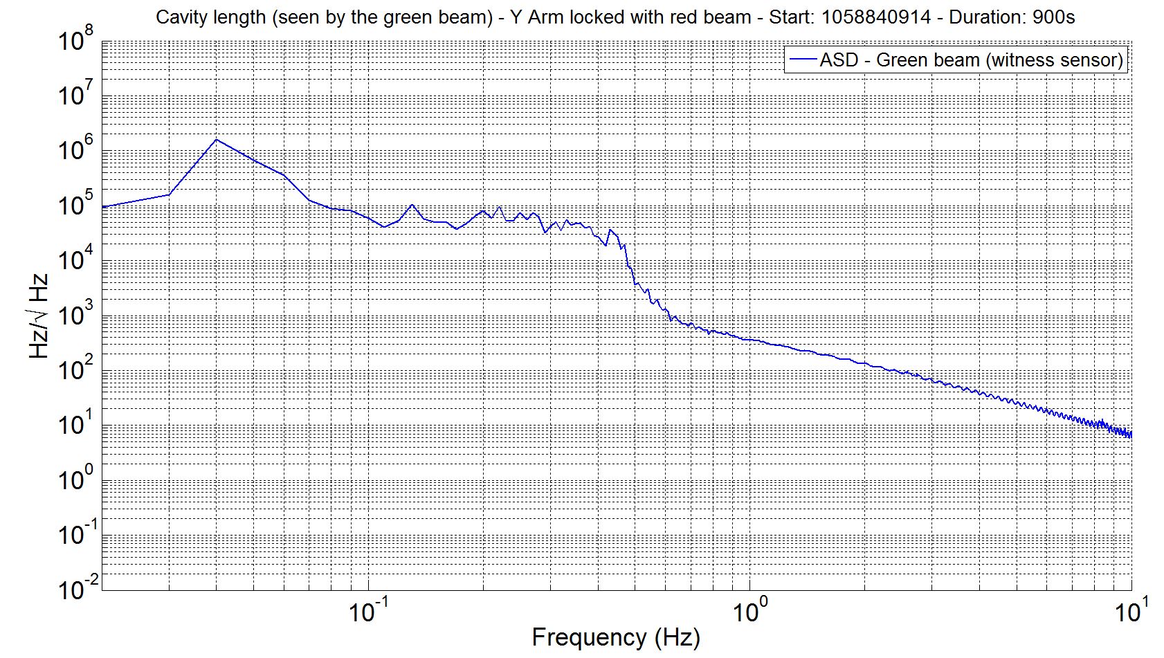
2- ASD of the arm’s length seen by the green beam
The ASD of the green beam is presented in attachment (H1_GB_Cavity_Length_Red_Lock_20130726.jpg).
The large motion seen around 40mHz is created by the ISI (mainly ETMY cf Coherence). The aggressive filters used for the sensor correction strongly amplify the ISI motion around 50mHz. It’s a tradeoff between amplification below 100mHz and a “0 degree phase” above 100mHz.
3-Coherence from the ISI drives to the cavity length
Once the HEPI and the ISIs are controlled (ground excited only), I used the control drive (Isolation filters output, damping filters output negligible) to evaluate the coherence from the drive to the length of the arm. Coherence in the bandwidth of interest (0-200mHz) are presented in the video at: https://svn.ligo.caltech.edu/svn/seismic/BSC-ISI/H1/Common/Misc/Video/H1_ISI_Coherence_Cross_Coupling_20130725.avi, channels are:
- 1 to 6: ETMY stage 1 drive in the direction X, Y, Rz, Z, Rx, Ry
- 7 to 12: ETMY stage 2 drive in the direction X, Y, Rz, Z, Rx, Ry
- 13 to 18: ITMY stage 1 drive in the direction X, Y, Rz, Z, Rx, Ry
- 19 to 24: ITMY stage 2 drive in the direction X, Y, Rz, Z, Rx, Ry
- 25: Y-arm length
NB: Index 1,1 is at the bottom left (The diagonnal is going up). The matrix is symmetric.
From 40mHz to 60mHz where the motion is maximal, the coherence matrix shows:
- the 2 ISIs were maybe in a different state (block matrix 1:12,1:12 very different from 13:24,13:24). Was the sensor correction engaged properly on ITMY? It is difficult to evaluate at posteriori. The sensor correction might be also less effective on ITMY since the STS-2 installed in the beer garden is relatively far from the chamber (in comparison with ETMY). Is there a reaction from the HEPI (locked in for ITMY and unlocked for ETMY)?
- ETMY
-The coherence is important from stage 1 Y drive to length, stage 1 Ry drive to length and stage 2 Y drive to length.
- The cross coupling drives are important
- There is an important Z to Rz cross coupling (bad positioning of the horizontal CPS)
- ITMY
- There is some coherence from stage 1 Y drive to length, stage 1 Ry drive to length and stage 2 Y drive to length. The coherence from the drives to the length is globally lower than ETMY.
- The cross coupling drives are moderate
- There is an important Z to Rz cross coupling (bad positioning of the horizontal CPS)
Some measurements are currently running to evaluate the tilt (X->RY and Y->Rx). The translation to tilt coupling will be used to correct the position sensor signals. This correction is used to take care of the CPS misalignment.
We can also notice a good coherence between the two ISIs on stage 1 in the Y and Z direction and stage 2 in the Z direction.
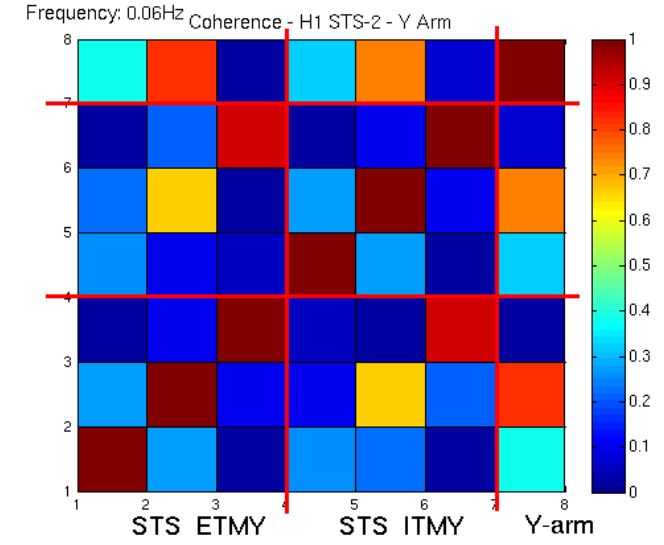
4- Coherence between the STS-2s and the arm
The coherence between the STS-2 and the arm is presented in the video https://svn.ligo.caltech.edu/svn/seismic/BSC-ISI/H1/Common/Misc/Video/H1_STS2_Coherence_Cross_Coupling_20130725.avi Channels are:
- 1:3: ETMY STS-2 X,Y,Z
- 4:6: ETMY STS-2 X,Y,Z
- 7: Y-Arm
The coherence at 60mHz is shown in attachment H1_STS2_Coherence_Cross_Coupling_20130725.jpg. Around 60mHz, the coherence between the corner station and the EY is important in the Y and Z directions. The coupling beween the ground Y direction is important. The ground motion is amplified by the sensor correction of the ISI then visible in the cavity.
5- Contribution of the drives in the arm's length
I am currently trying to evaluate what is the contribution of each drives in the arm.