(Stefan, Alexa)
We calibrated the PDH locking signal of the REFL beaming using Stefan's calibration scheme below (reference SUGWG lab logbook):
Motivation:
Easy way to calibrate a PDH error signal in Hz/Volt.
Input:
* Cavity pole frequency f0 (See next entry on how to measure this.)
* Maximum (peak) voltage of the error signal in a slow cavity scan: Vmax
Result: gain at lock point = f0/(2*Vmax)
Description:
The cavity resonance amplitude transfer function can (for high finesse cavities) be accuracy described by a Lorentizan:
TF = 1/(1+if/f0)
where f is the frequency offset from resonance. A phase modulated carrier field
Psi = 1 + i*exp(iwt) +i*exp(-iwt)
thus becomes
Psi_r = 1/(1+if/f0) + i*exp(iwt) +i*exp(-iwt)
The DC and 1-w part of |Psi_r|^2 are therefore
|Psi_r|^2 = 1/(1+(f/f0)^2) * ( 1 + [(1+if/f0)*(+i) + (1-if/f0)*(-i)]*exp(iwt) + C.C. )
Therefore the DC PDH error signal is
error/2 = [(1+if/f0)*(+i) + (1-if/f0)*(-i)] / (1+(f/f0)^2) = -2(f/f0) / (1+(f/f0)^2)
This has a maximum of 1 for f=f0 (see attached hand-written note). Therefore the full calibrated error signal is (sign omitted)
PDH_error = 2*Vmax*(f/f0) / (1+(f/f0)^2)
which has the slope 2*Vmax/f0 [Volts/Hz] around the locking point.
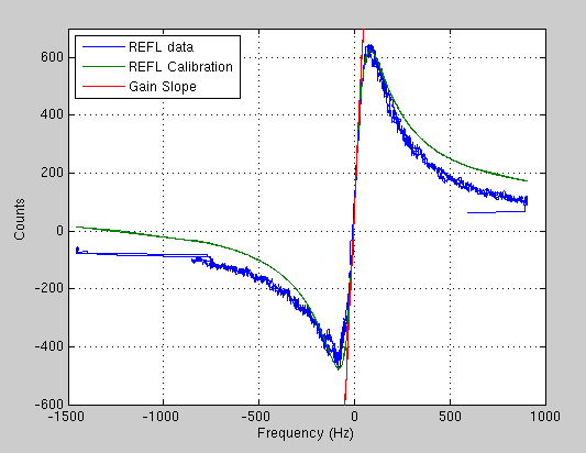
I created a script that imports the transmitted light (H1:ASC-Y_TR_A_NSUM_OUT_DQ) and reflected light (H1:LSC-REFLAIR_A_RF9_I_OUTMON) data. With this data, we follow the above calibration and create a fit. The script and results are attached. The graphs include the collected data and the calibration fit. The graph of the REFLAIR channel also includes the gain locking slope in red. From fitting the calibration to the data we succeeded in making a cavity pole meaurement of 82Hz. We also found the peak of REFLAIR to be 550 counts.