christopher.wipf@LIGO.ORG - posted 15:45, Wednesday 26 June 2013 (6894)
new library parts for ALS
The following new RCG library parts have been added to the repository for use with the ISCEY/ALS model.
-
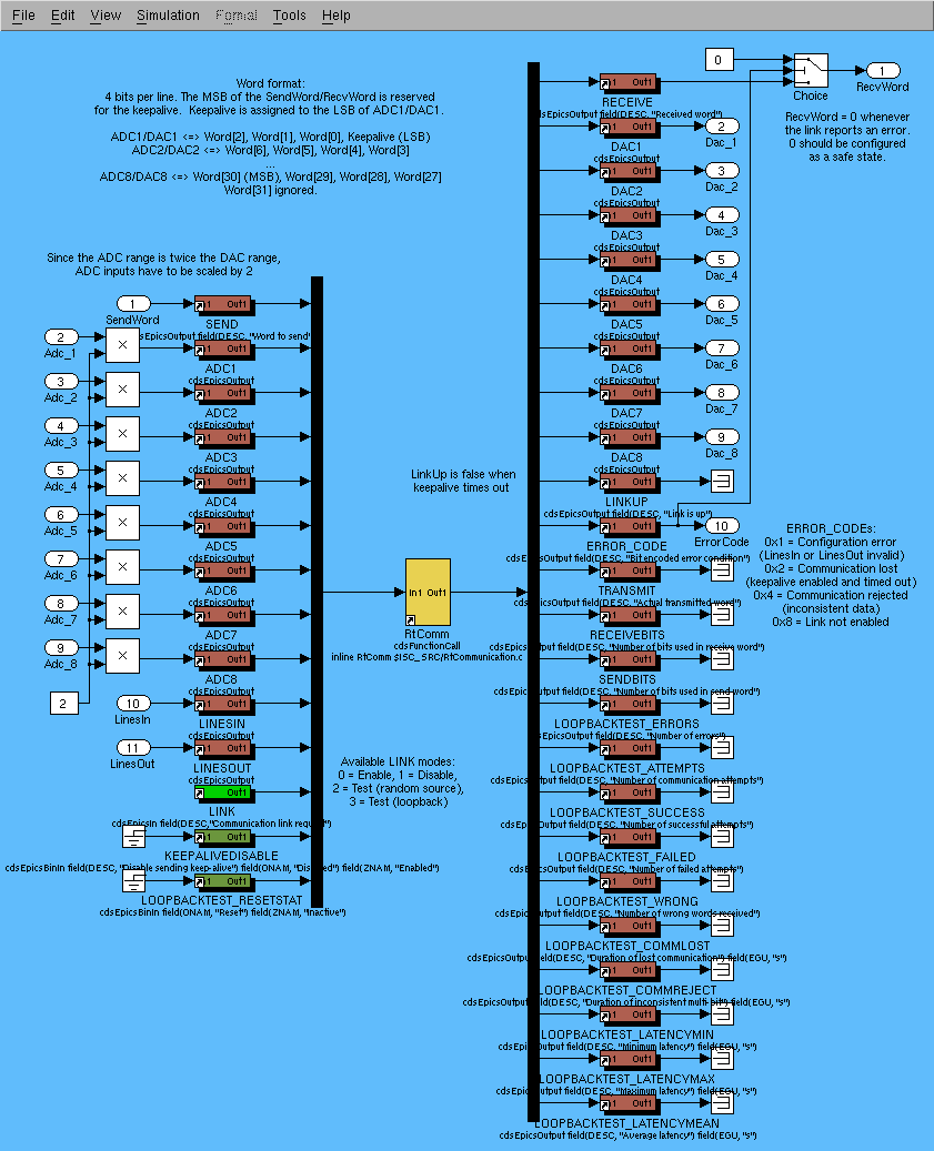
Communication link with Beckhoff (in .../isc/common/models/STATECOMM.mdl, plus C source code in .../isc/common/src/RtCommunication.c)
This part interacts with the RtCommunication.lib library in the Ethercat slow controls system (documented in E1300442), allowing it to exchange state bits with the realtime front ends via ADC and DAC channels.
(see attachment 1 for detail) -
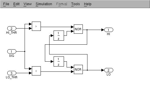
Schmitt trigger with HI and LO outputs (in .../cds/common/models/SCHMITTTRIGGER.mdl)
This was added alongside the already existing Schmitt trigger module, which only provides a HI output. (Since this is a hysteretic trigger, LO is not the same as NOT HI.)
(see attachment 2 for detail) -
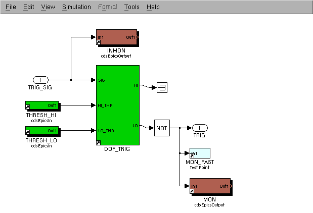
RMS trigger (in .../isc/common/models/LSC_TRIGGER.mdl)
Added alongside the LSC trigger part, this part provides the complementary behavior (activating a trigger when the input signal goes LO). This is useful when the input signal is an RMS.
(see attachment 3 for detail)
Images attached to this report