kyle.ryan@LIGO.ORG - posted 16:22, Thursday 06 June 2013 (6659)
Opened GV1
In preparation of the acceptance documentation for HSTS suspensions, PRM top mass has been tested for phase 3b after the series of MCs.
The transfer functions are showing good agreement with model and previous measurements.
The attached file is a comparison between model, phase 3a and phase 3b
files and data have been commited on the svn under the following directories :
/ligo/svncommon/SusSVN/sus/trunk/HSTS/Common/${MatlabTools/Data}
/ligo/svncommon/SusSVN/sus/trunk/HSTS/H1/PRM/SAGM1/${Data/Results}
I kept forgetting to ask this question : what do these "3a" and "3b" mean ?
See G1200070, Ideal Order/Contents of aLIGO Triple SUS Testing / Commissioning, https://dcc.ligo.org/LIGO-G1200070.
1a: Metal build assemblies, in initial assembly area (e.g., LHO staging building)
1b: Metal build fully assembled, in initial assembly area
2a: Metal build chamberside
2b: Glass build chamberside
3a: Glass build in chamber, before pumpdown
3b: Glass build in chamber, after pumpdown
Unlocked BSC2 - Hugh

Close GV-1 to leak check - Kyle & John

Install illuminator and camera on BSC2 - Richard M

Align and level X test stand - Doug & Jason

Check laser welder alignment - Doug & Jason

Assemble E-module and spiral staircase - Apollo

Lift BSC CR on crane, leaving suspended overnight - Apollo

Valve in YBM Turbo and leak detector combination to exposed Y-arm - Kyle
The E-module was assembled and married to the spiral staircase: some transitional plates between the E-mod and the work platform will need to be fabricated and installed when convenient. The Tech Cleaners did the first round of cleaning at BSC9. The Test Stand was craned over the beamtube into position near the roll-up door. Modification of the BSC CR legs to accommodate the leg jacks was started: the ceiling of the CR will be suspended on the crane overnight. The remote control for the crane will be at the corner overnight as a LO-TO measure. All but four bolts were removed from the dome: bolts will come out of the door tomorrow.
In preparation for acceptance of H1 SUS TMSY, I've been asked to model its performance. I accepted given that we've got a state-space model and parameter set that's been confirmed by measurement and it's straight-forward to adopt the loop performance figures of merit from the software suite developed for the QUAD and BSFM Level 2 designs. Here I merely show results that confirm the model's accuracy using the current filters before I move forward with the Level 2 filter design.

The new software suite for the TMTS (which will be useful for the OMCS when it comes online soon as well), can be found here:

${SusSVN}/sus/trunk/TMTS/Common/FilterDesign/
design_damping_TMTS_20130313.m (script where overall design is done)
    - plottmtsdampingcontroldesign.m (function that takes in newly designed filters and computes the performance figures of merit)
        - plottmtsactuatornoise.m (sub-function that computes the actuator noise component of the model)

In addition, I've added the TMTS requirements (based on Fig 18 of E1100537) to the function

${SusSVN}/sus/trunk/Common/MatlabTools/SUS_reqs.m


I won't bore you with all of the plots that this suite produces since this has only been run on the Level 1 design of the filters, but I will post results of this morning's transfer functions, and a tease of why the TMTS filters need some tweaking. I'll focus on Pitch, since that (with Yaw) are the DOFs with the most stringent requirements for the TMS, and since L and P were the only DOFs I had time to measure.

Three plots:
(1) dampingfilters_TMTS_20130313_loopmeas_P.pdf A comparison between the modeled and measured open loop gain transfer function. It confirms the stability, and we now see the model is only off by the usual known quantities:
- ~50% under in magnitude (mostly likely due to a systematic scale factor error in the model calibration -- no biggie),
- a tiny fraction in resonant frequencies (due to modeling the "ideal" suspension properties as opposed to the "real" properties)
- some unmodeled time delay-like feature in the phase.

(2) dampingfilters_TMTS_20130313_loopdesign_P.pdf A loop design plot showing all of the useful figures of merit, the open loop gain transfer function (G), the suppresion (1 / (1+G)), and the closed loop gain transfer function (G / (1+G)). Note, I use the standard convention for loop gain with the explicit -1, such that the stability criteria is that lower unity gain crossings must stay away from +180, and upper unity gain crossings must stay away from -180, with no phase wraps in between the first LUGF and the last UUGF.

(3) dampingfilters_TMTS_20130313_totalbudget_P.pdf A noise budget based on the loop design.

------
For the record, the filters currently in place (and ON) are (using [zeros:poles:gain] notation, and "pair" to represent a complex pair of zeros or poles at frequency of the first argument, and phase of the second. Both arguments are rounded to the nearest integer for brevity)

L FM1 "damp30" [0:30,100:1],             FM5 "from_um" [::43.478], FM10 "ELF10" [pair(16,86),pair(36,56):pair(6,51),pair(10,79):1], G = -20.0
T FM1 "damp30" [0:30,100:1],             FM5 "from_um" [::43.478], FM10 "ELF10" [pair(16,86),pair(36,56):pair(6,51),pair(10,79):1], G = -10.0
V FM1 "damp30" [0,1:0.3,30,100:3.51521], FM5 "from_um" [::43.478], FM10 "ELF10" [pair(16,86),pair(36,56):pair(6,51),pair(10,79):1], G = -20.0
R FM1 "damp30" [0,1:0.3,30,100:3.51521], FM5 "from_um" [::43.478], FM10 "ELF10" [pair(16,86),pair(36,56):pair(6,51),pair(10,79):1], G = -0.05
P FM1 "damp30" [0,1:0.3,30,100:3.51521], FM5 "from_um" [::43.478], FM10 "ELF10" [pair(16,86),pair(36,56):pair(6,51),pair(10,79):1], G = -0.5
Y FM1 "damp30" [0,1:0.3,30,100:3.51521], FM5 "from_um" [::43.478], FM10 "ELF10" [pair(16,86),pair(36,56):pair(6,51),pair(10,79):1], G = -0.1

which is notably different that when I'd spruced up the TMTS, SUS style back in March (see LHO aLOG 5754, and LHO aLOG 5781), when the different Yaw filter in FM2, and any boosts that were found in FM2 were ON. I didn't see any aLOG of this configuration change, so my guess is this was an old configuration that stuck after a reboot (which is surprising because I specifically captured a new safe...)

I've copied the foton file representing this configuration over to the userapps repo, and committed it to rev 4641
208-69-129-56:filterfiles kissel$ svn info H1SUSTMSY.txt
Path: H1SUSTMSY.txt
Name: H1SUSTMSY.txt
URL: https://redoubt.ligo-wa.caltech.edu/svn/cds_user_apps/trunk/sus/h1/filterfiles/H1SUSTMSY.txt
Repository Root: https://redoubt.ligo-wa.caltech.edu/svn/cds_user_apps
Repository UUID: e3bfa956-ff0e-4416-9af7-00b7a258cde5
Revision: 4650
Node Kind: file
Schedule: normal
Last Changed Author: jeffrey.kissel@LIGO.ORG
Last Changed Rev: 4641
Last Changed Date: 2013-06-06 14:35:30 -0400 (Thu, 06 Jun 2013)
Text Last Updated: 2013-06-06 14:45:31 -0400 (Thu, 06 Jun 2013)
Checksum: e5032b936a0f52fd58cfd2ec15dd771b


------
Also, the data (for L and P only thus far) was taken with the following templates:

2013-06-06_1511_H1SUSTMSY_M1_L_WhiteNoise_OLGTF.xml
2013-06-06_1511_H1SUSTMSY_M1_P_WhiteNoise_OLGTF.xml

which notably improve on the standard SUS white noise DTT excitation: in order to get more coherence at low frequency, I added a zpk([0.5;0.5],[0.05;0.05],100,"n") to the Filter field in the Excitation Tab of the measurement. This adds a factor of 100 gain at low frequency (filtered out by 1 [Hz]) where the coherence is the worst, and we're not plagued with DAC saturations because on the anti-dewhitening filters in the COILOUTF banks (which start adding gain above 1 [Hz]). This way I can jack up the overall gain of the measurement at low frequency where we need it, without saturating the DAC nearly as quickly.
This chambers Actuators were moved from Bleed to Run State on Tuesday and the IPS sensors zero'd then as well. Unlocking them today sees significant motion especially as compared to HAM1 this morning. At HAM1 the motion on release was 2 mils or less. Here at BSC2 the vertical moved down (uniformly) 13000 counts or about 20 mils. The horizontal shift was half or less than the vertical shift with the motion being East with some minor CCW rotation.
Yesterday late afternoon GregG switched the HAM1 Actuators from Bleed Mode to Operation Mode; this chamber had been bleeding since 20 May.  The IPS sensors were also zero'd yesterday.

This morning, we unlocked the HEPI, so HAM1 is now floating; the caution signs have been changed.  Please be mindful of all the blue hardware at HAM1.

Also, please avoid using the HEPI Housing area as a tool/parts holder.  There are many very close clearances in the HEPI Mechanical structure and a dropped screw or tool could render them bound up.  This will/could be very difficult to diagnose/find as most of these tight spaces are not visible and barely probeable.
After adding a few channels to the ITMY .ini file, I rebooted the DAQ at 10h03. During the DAQ restart, the daqd process did not come back. It was restarted manually around 10h40 (Dave remotely).
GV1 was closed at ~16:47 utc or 9:47 local time.
Just a heads up, I'll be taking transfer functions remotely on TMSY this morning. HIFO-Y work takes precedent over this, so don't hesitate to call me and tell me to stop!
I've finished my work for the day. Will pick up again early tomorrow morning unless there are objections from the commissioning crew.
Attached are plots of dust counts requested from 5 PM June 4 to 5 PM June 5.

Both the dust monitor at location 14 in the LVEA (H2 PSL enclosure) and the dust monitor at location 16 in the LVEA (H1 PSL anteroom) are indicating calibration failures.
(Jax, Alexa, Arnaud, Chris, Sheila, Daniel, Stefan)

We implemented the DC relief to ETMX for the ALS lock

- Implemented a IPC link from H1:ASL-Y_ETM_LONG to H1:SUS-ETMY_L3_ISCINF_L_IN1.
- Added dewhitening filter to H1:ALS-Y_REFL_SMON FM1 (Zeros 10Hz, 10Hz; Poles 100Hz, 100Hz).
- Zerod the electronic offsets in the CM board B and slow path (H1:ALS-Y_REFL_SERVO_COMOFS=0.505V, H1:ALS-Y_REFL_SERVO_SLOWOFS=-1.675V, H1:ALS-Y_REFL_SMON_OFFSET=-1645).
- Added 1/f filer in stages (Z:P: 10:1:0, 1:0.1, :1) and gain of -0.03 in H1:ALS-Y_ETM_LONG filter bank.
- SUSETMY is in "distributed feed-back mode". We feed back only to the top mass.
- H1:SUS-ETMY_L3_ISCINF_L and H1:SUS-ETMY_M0_LOCK_L have a flat gain of 1.

We also killed a 1.3Hz oscillation in the light from the fiber by putting a 20dB,Q=3 resonant gain into the H1:IMC-L path. All this, together with another alignment tweak, made for very stable locks: while I am writing this log the arm stays locked for 20min at a time while the relief integrator is ticking away (Tidal?). I set the limiter H1:ALS-Y_ETM_LONG_LIMIT to 10000 cts to prevent kicking the Quad too hard - this eventually breaks the lock.

Sheila and I quickly took a peak, but there is no green beam coming out at the corner yet. Not too surprising,.. next we need to align the IR beam to hit the ETM cage.

Things to do with low priority:
- Decouple force to pitch (& yaw) at DC - the alignment degrades slightly for O(1e4) counts of M0 length drive. But its likely good enough for the HIFO work.
[Chris, Kiwamu]
This is a detailed version of the previous IMC WFS entry (see alog 6633).
Actuation issue wasn't really an issue:
We kept driving the M3 stages (very bottom stage) of MC1 and MC3 to excite the angular motions (alog 6610) but it turned out that this was not the right way. The actuators on M3 are simply not strong enough to excite them with a high signal-to-noise ratio at the wave front sensors. Therefore we need o switch the driving point from the M3 to M1 (very upper stage) to have a big excitation. In fact this is the way the people in Livingston did. After all, exciting M1 gave us a prominent peak in the spectrum of the WFS signals and hence we were able to proceed with the measurement of the sensing matrix.
Balancing of the quadrant segment gain:
During adjusting the demod phase of each segment of the WFSs we noticed that they show different signal gain. In order to correct this gain discrepancy among the segments we changed the digital filter gain to make them identical. We excited the longitudinal motion of the IMC by injecting a 6 Hz sinusoidal signal at INPUT2 of the IMC common mode board servo with an amplitude of 80 mVp-p. This resulted in a peak in the spectrum of each quadrant. Then we adjusted IMC-WFS_A(B)_IX_GAIN and IMC-WFS_A(B)_IX_GAIN where X = 1,2,3,4. Here is the resultant gain coefficients. We are not sure why the gains vary by a factor of 5 at most among the segments. This variation can not be explained by the discrepancy in the transfer gain of the demodulation chain.
H1:IMC-WFS_A_I1_GAIN = 1
H1:IMC-WFS_A_Q1_GAIN = 1
H1:IMC-WFS_A_I2_GAIN = 5.33
H1:IMC-WFS_A_Q2_GAIN = 5.33
H1:IMC-WFS_A_I3_GAIN = 4.43
H1:IMC-WFS_A_Q3_GAIN = 4.43
H1:IMC-WFS_A_I4_GAIN = 1.33
H1:IMC-WFS_A_Q4_GAIN = 1.33
H1:IMC-WFS_B_I1_GAIN = 5.75
H1:IMC-WFS_B_Q1_GAIN = 5.75
H1:IMC-WFS_B_I2_GAIN = 1
H1:IMC-WFS_B_Q2_GAIN = 1
H1:IMC-WFS_B_I3_GAIN = 1.07
H1:IMC-WFS_B_Q3_GAIN = 1.07
H1:IMC-WFS_B_I4_GAIN = 5.47
H1:IMC-WFS_B_Q4_GAIN = 5.47
Compensation for the geometrical rotation:
As far as we remember there is a periscope in the IMC-REFL path which rotates the x-y relation of the beam, which rotates it by almost 90 degrees. Due to this effect the actual yaw motion happening in the IMC cavity shows up as almost pitch motion and vice versa at the RFFL port. We corrected this effect by manipulating the input matrix (IMC-WFS_A(B)_I_MTRIX) such that the yaw excitation shows up only in pitch basis after the input matrix. This adjustment was done by exciting the M2 stage of MC2 (which somehow we ended up with for some reason when exciting the angular motions) in pitch and yaw at 3 Hz. As a result the coupling between pitch and yaw were improved and separation ratio became approximately a factor of 50 at least which used to be 1 at worst. Here is the resultant matrix elements.
H1:IMC-WFS_A_I_MTRX_1_1 = 0.478812
H1:IMC-WFS_A_I_MTRX_1_2 = -1.33069
H1:IMC-WFS_A_I_MTRX_1_3 = -0.478812
H1:IMC-WFS_A_I_MTRX_1_4 = 1.33069
H1:IMC-WFS_A_I_MTRX_2_1 = 1.33069
H1:IMC-WFS_A_I_MTRX_2_2 = 0.478812
H1:IMC-WFS_A_I_MTRX_2_3 = -1.33069
H1:IMC-WFS_A_I_MTRX_2_4 = -0.478812
H1:IMC-WFS_B_I_MTRX_1_1 = 0.394297
H1:IMC-WFS_B_I_MTRX_1_2 = -1.35813
H1:IMC-WFS_B_I_MTRX_1_3 = -0.394297
H1:IMC-WFS_B_I_MTRX_1_4 = 1.35813
H1:IMC-WFS_B_I_MTRX_2_1 = 1.35813
H1:IMC-WFS_B_I_MTRX_2_2 = 0.394297
H1:IMC-WFS_B_I_MTRX_2_3 = -1.35813
H1:IMC-WFS_B_I_MTRX_2_4 = -0.394297
Measurement of the sensing matrix
The measurement of the sensing matrix went very smooth. We excited the M1 stage of the IMC suspensions. We considered two DOFs in pitch (yaw), namely common (differential) MC1-MC3 and MC2. This is the DOF basis that the Livingston people came up with in the IMC WFS commissioning. The excitation was injected to DOF_1(2)_Y(P)_EXC with an amplitude of 10-12 counts at about 3 Hz. To be sure that we are exciting the pure pitch or yaw we looked at the witness channels for the bottom stage and confirmed that we were exciting the right angular motion. Since we didn't have an auto-script to measure the sensing matrix we used diaggui to measure the transfer coefficient from the excitation to the WFSs. After measuring the 2x2 sensing matrix we inverted it and put it to the control input matrix IMC-INMATRIX_P(Y). In diaggui the frequency resolution was set to 0.01 Hz. Here is the resultant input matrix.
H1:IMC-INMATRIX_P_1_1 = 0.64725
H1:IMC-INMATRIX_P_1_2 = -0.35275
H1:IMC-INMATRIX_P_2_1 = -0.159639
H1:IMC-INMATRIX_P_2_2 = 0.840361
H1:IMC-INMATRIX_Y_1_1 = -0.163134
H1:IMC-INMATRIX_Y_1_2 = -0.836866
H1:IMC-INMATRIX_Y_2_1 = 0.529564
H1:IMC-INMATRIX_Y_2_2 = 0.470436
Closing the loops:
The trial of closing the loops were relatively easier compared with what we did to reach this point. We simply started from a small gain of 1e-4 and we fiddled with the sign. Since this was the first time for us to close the loops we enabled only fundamental control filers, namely FM6 (0.06, 0.1) and FM7(0:1) of IMC-DOF_1(2)_P(Y) and disabled the rest of the fancy filters. We aimed an UGF of a few 10 mHz or so. The gains were adjusted by looking at the time scale of the control against a disturbance. The gains we ended with were :
H1:IMC-DOF_1_P_GAIN = -1e-05
H1:IMC-DOF_2_P_GAIN = -1e-05
H1:IMC-DOF_1_Y_GAIN = -1e-05
H1:IMC-DOF_2_Y_GAIN = -1e-05
What are missing ?:
The DOF3 (MC2 TRANS centering) loops have been turned on, currently with very low UGF (step response ~minutes).  They worked "out of the box" using the LLO filters, and a bit of tweaking of the DOF3 gains.

Under $USERAPPS_DIR/ioo/h1/scripts/imc there's a new script, mcwfsrelieve, which offloads the DOF1/2/3 outputs onto the downstream filter modules (H1:IMC-MC1_PIT et al).

There's also a rudimentary_autolocker script for the IMC (temporary stopgap until the Guardian is up and running here).

Though we have plenty of optimization left to do, the IMC now has a reproducible baseline configuration, which is its main requirement during HIFO-Y.
Valved-in YBM Turbo and sporadically sprayed helium (audible flow) around chambers and misc. ports of Vertex volume currently under vacuum looking for any "easy" big leaks -> detector baseline 4 x 10⁻⁹ torr*l/sec -> Note, this exercise does not constitute a "leak test" -> Will do formal leak hunting as opportunities present themselves over the next few days? weeks?
Modification to external piping recently completed by Apollo -> Entire annulus volume (including gate annulus) had been vented to facilitate this mod -> Gate annulus volume is temporarily combined with rest of annulus volume being pumped by aux. cart -> 1.5" all-metal isolation angle valve to be closed after a few days to re-isolate gate annulus volume (i.e. restore nominal configuration).
The concrete floor at the spool was covered with CPStat after the PEM fence was removed. The CPB jigs were moved to the far side of the beam tube by Apollo and then the tech cleaners removed Sharpie and other egregious "stuff" from them.The ISI storage container top was removed from the VEA and taken to X-Mid. The E-module and spiral staircase were moved down to the end and then the E Module was moved into the VEA.

A small piece of vinyl was torn up by the big pallet jack used for the ISI. Since the tear is in the Test Stand area, John is contacting the vendor to get a repair taken care of before the ISI is in place.
Morning Alarms:
- CDS all are CPU Max and IOP watchdogs - no action necessary
- Dust alarms are all due to working people - no action necessary

Morning work:
- forklift work near test stands in LVEA

Currently:
- Filiberto in LVEA fixing cables on the CM servo board.
(Jax, Alexa, Stefan, Sheila, Daniel)
Arm locking achieved!
As of 18:00 local time, we're getting lock to 00 at a level of 10000 cts on H1: ALS-Y_REFL_B_LF_OUT, out of a maximum of about 22000 cts. This is about a 50% drop.
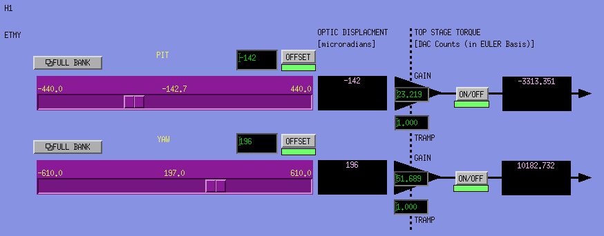
We've touched up the pitch and yaw to improve locking characteristics. The current positions in pitch/yaw are
ETM: (-142.7, 197.0)
ITM: (247.5, -271.5)
The current gain on CMB-B input 1 is -18 dB.
Key for the stable locking was increasing the M0_DAMP filters for Length, Pitch and Yaw from a gain of 1 to 5 (Vincent pointed me to it.).
This quieted down the cavity angular motion enough that it became possible to do a good manual alignment. (see Jax' elog for alignment values).
(This also confirms that the 0.5Hz pich motion we observed was due to the Quads.)

Now the alignment is very steady, and almost all of our lock losses are associated with H1:ALS-Y_REFL_FMON_OUT reaching plus or minus 5000 counts, indicating a control signal range problem.
Some screen shots for documenting the state.
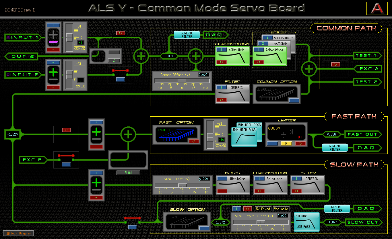
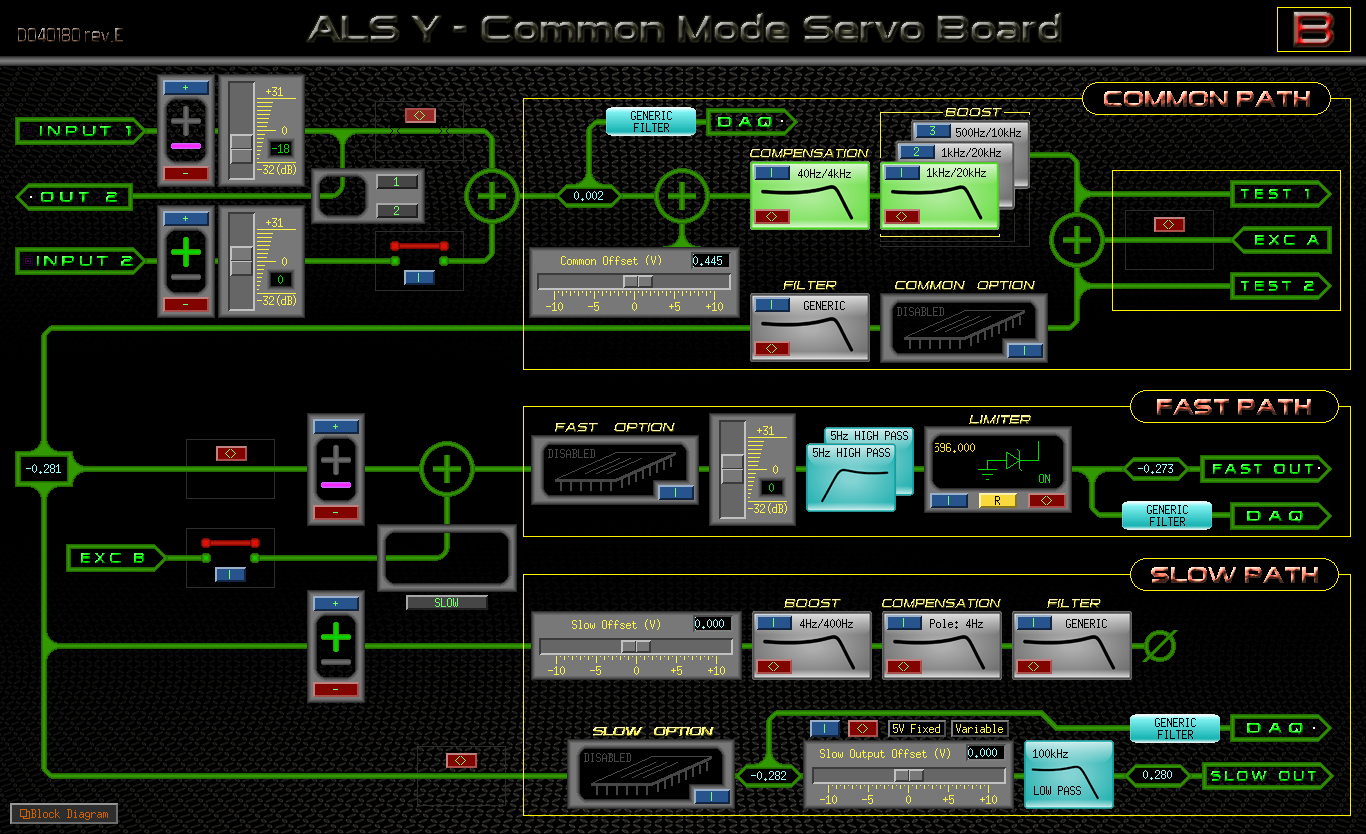

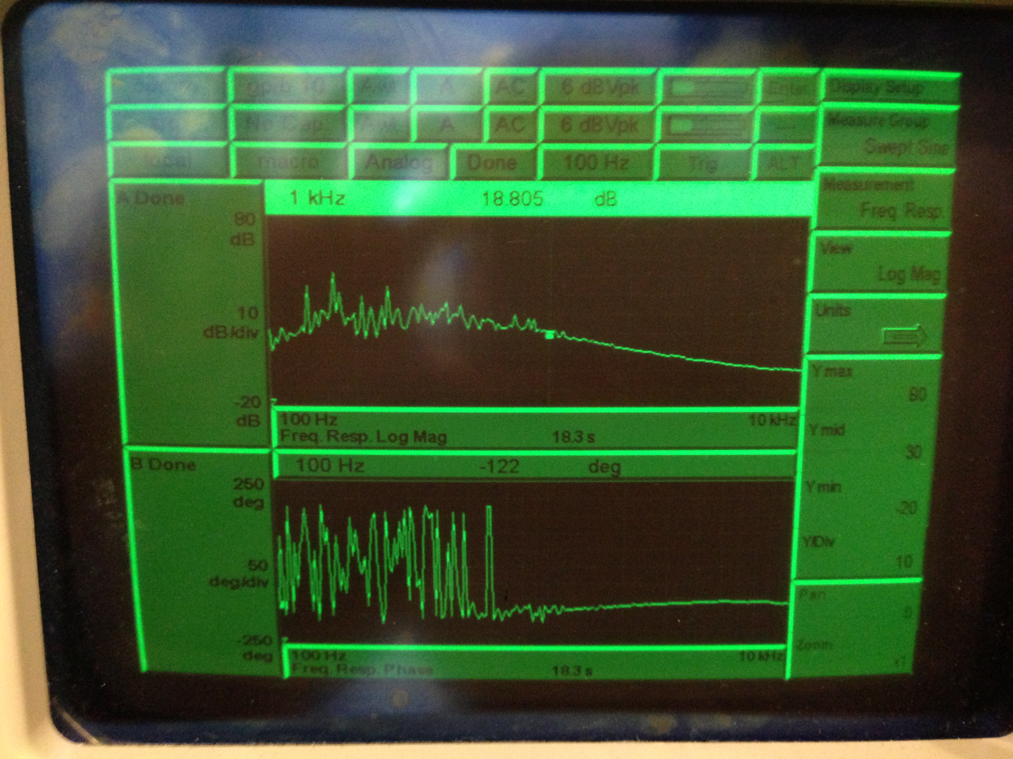
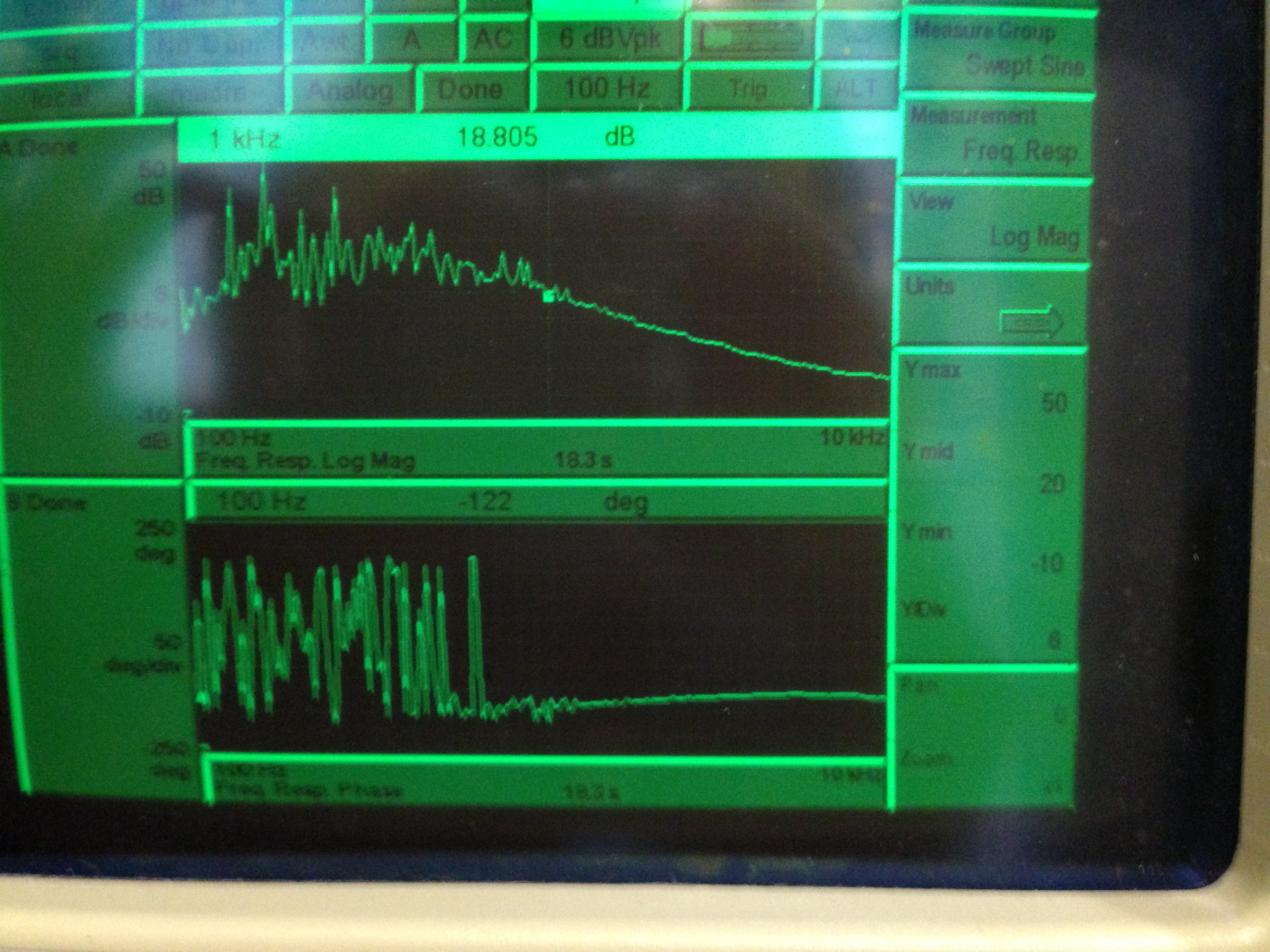
(Jax, Alexa)

Attached is a picture of the transfer function for the ALS cavity locking common mode board B of excitation A. (Note the two different images have a different y-axis scale).
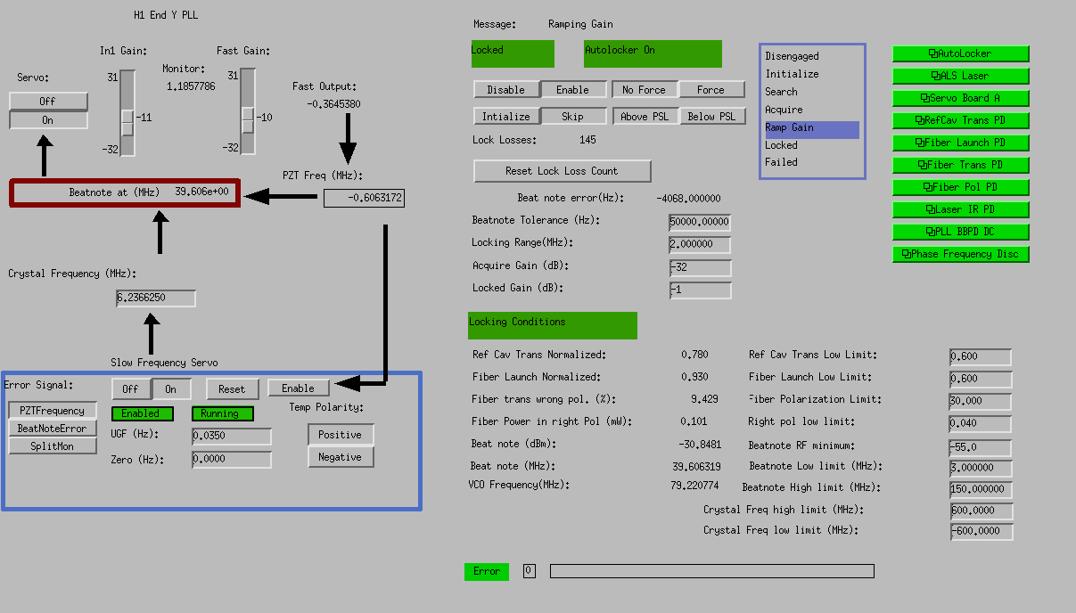
We changed the settings of the ALS laser at the end station, they are now:
diode current 1.842
diode temp: 31.38
SHG crystal temp: 33.81

We also looked at the transfer function for the PLL. With the settings we were using (in1 gain =-4, fast gain =-10, common comp and fast option enabled) the ugf was 10kHz, we have now set the in1 gain to -1dB and the ugf is 17kHz.  We are also able to enable one common boost, which has been added to the autolocker.  I also shortened the gain ramping time.

I also changed the fiber distribution library, so that the RF mon can drift by 2dB without causing an error.
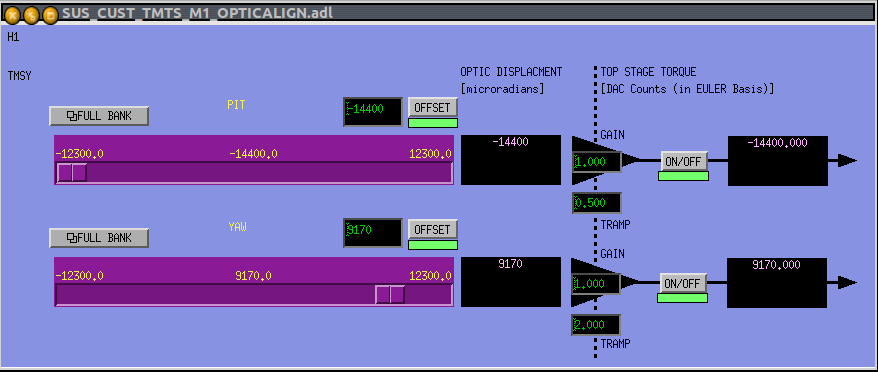
As requested by Daniel, the TMS pointing is (-14400,9170). This hasn't changed from initial alignment conditions (yet).
Here are the positions of the BSC-ISI. CPS offsets are presented in nm.
HEPI-BSC1: Locked https://alog.ligo-wa.caltech.edu/aLOG/index.php?callRep=6566
HEPI-BSC6 is control in position
ISI-BSC6: Blend at 250mHz with T240 and level 3 controller
ISI-BSC1: Blend at 250mHz with T240 and level 1 controller
| June 4, 2013, 18h00PT | ISI | ||
| DOF | ETMY | ITMY | |
| ST1 | X | 28272 | -22465 |
| Y | 23662 | -19540 | |
| RZ | -34715 | -3175 | |
| Z | 27000 | 12970 | |
| RX | 41889 | 6608 | |
| RY | -2182 | -20265 | |
| ST2 | X | -1158 | -5465 |
| Y | 2122 | -4336 | |
| RZ | -21183 | -7981 | |
| Z | 7428 | 15438 | |
| RX | -13021 | 18375 | |
| RY | 833 | -10010 | |
