jodi.fauver@LIGO.ORG - posted 12:19, Tuesday 04 June 2013 (6616)
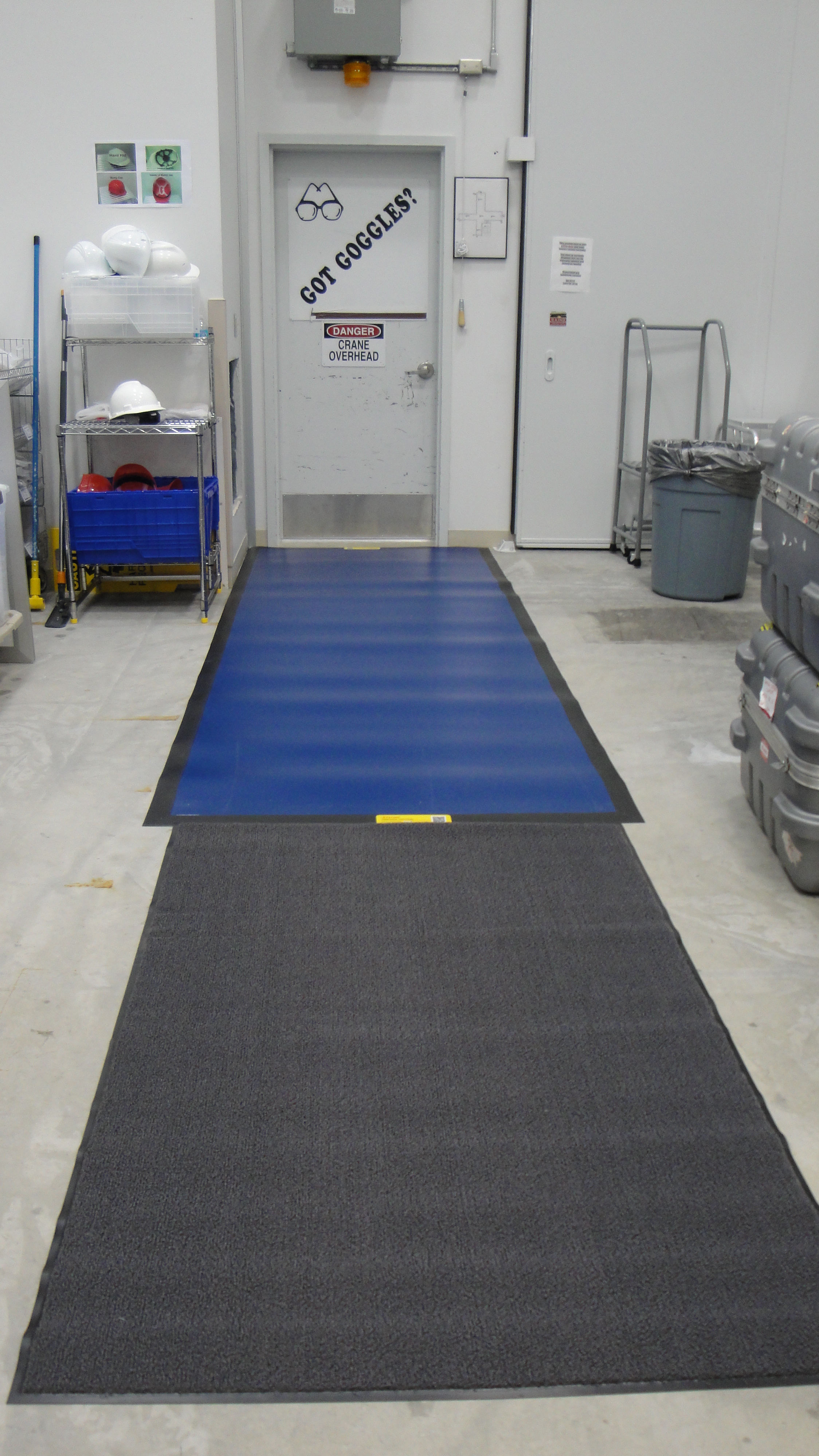
Dycem Floor Mats Installed at main LVEA Man Door
A contamination control test is under way at the main LVEA man-door entrance. You will notice that three frames of sticky mats have been removed and have been replaced by two large Dycem mats. The grey mat is for gross particulate removal and the blue mat is for fine particulate removal. The mats will be cleaned once per day.Picture below
Images attached to this report