sheila.dwyer@LIGO.ORG - posted 14:23, Friday 24 May 2013 (6504)
ALS PLL overnight
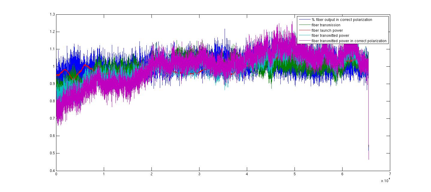
I left the ALS pll running overnight and this morning, using a 20 hour strip tool with a 1 second sample time it looks like the loop dropped lock 3 times, once for less than a second so that the autolocker did not respond, and the other two times the auotlocker had it relocked with the full gain after 62 seconds and 33 seconds.  Most of the time not in the locked at full gain is spent ramping the gain up from the acquire gain to the locked gain, we could speed up the ramp if this is too slow.

It was locked according to the locked bit 99.97% of the time, and locked in the full gain state 99.86% of the time.

I set the limits fairly loosly, to try to make sure the locking conditions were met overnight, and there were no times when the locking conditions were not met.

I also recorded the fiber launch power, fiber trans, and fiber transmitted power in the right polarization overnight.  There was about a 30% drift in the amount of power in the right polarization overnight, most of the drift does not seem to be due to a shift in polarization but in the transmission of the fiber itself.  A plot of the values I monitored overnight is attached, each one of these is normalized to its mean so that we can compare the trends.
Images attached to this report