jodi.fauver@LIGO.ORG - posted 14:48, Wednesday 24 April 2013 (6190)
HIFO Close-out-LVEA Update
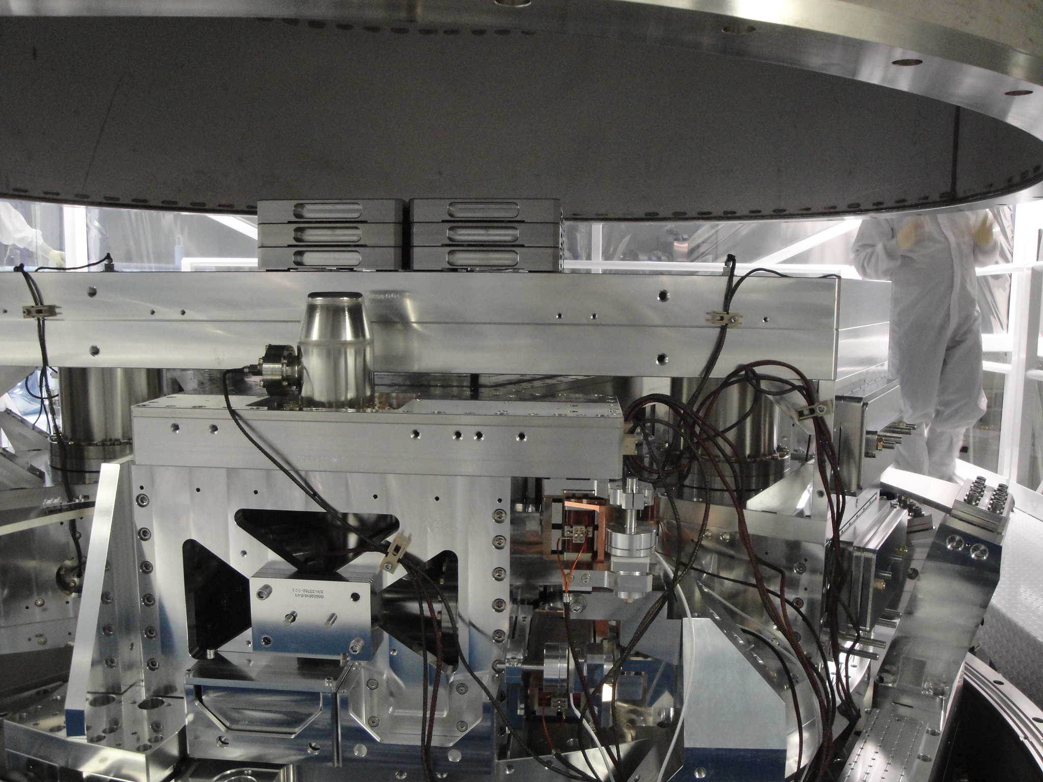
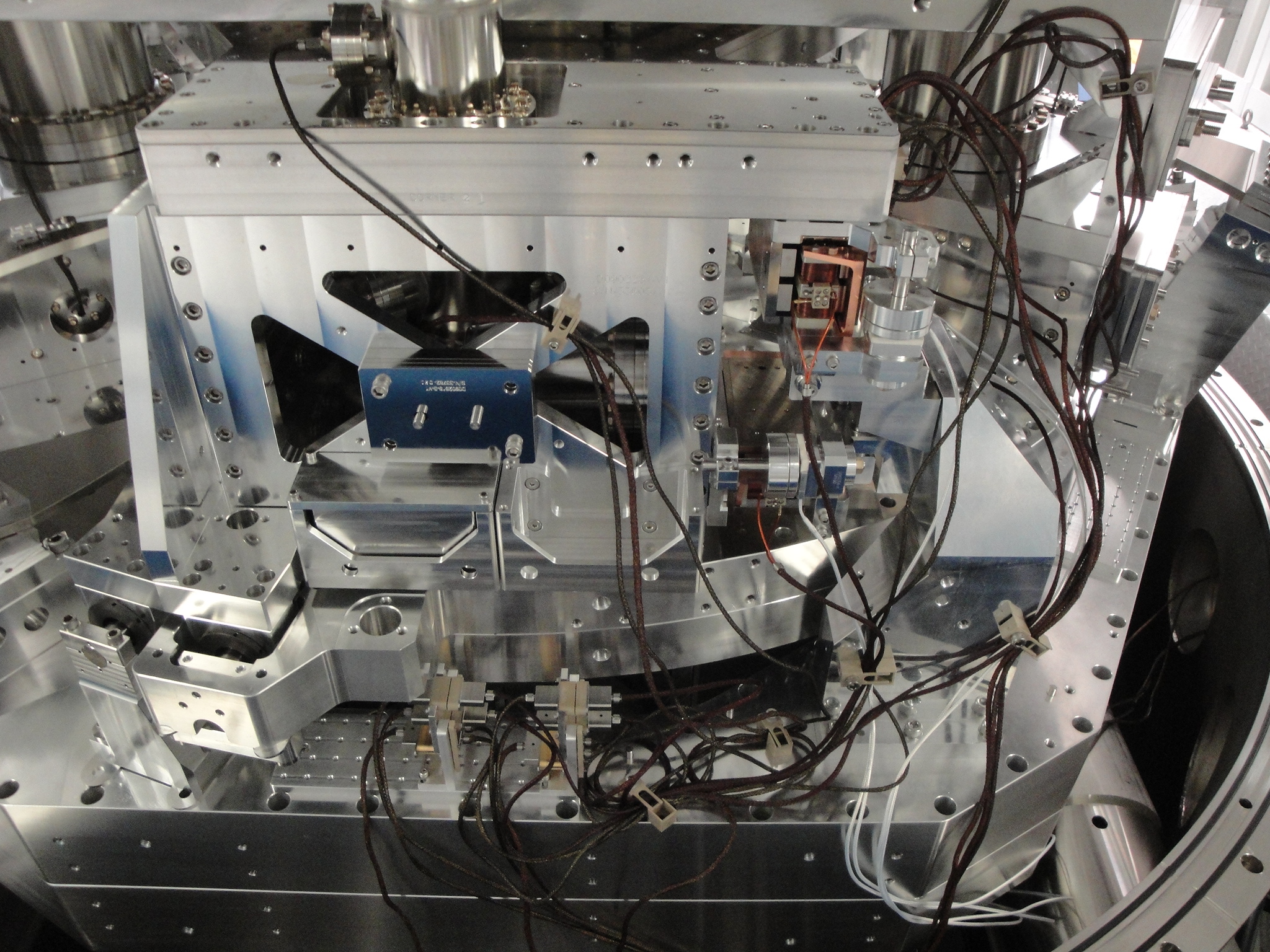
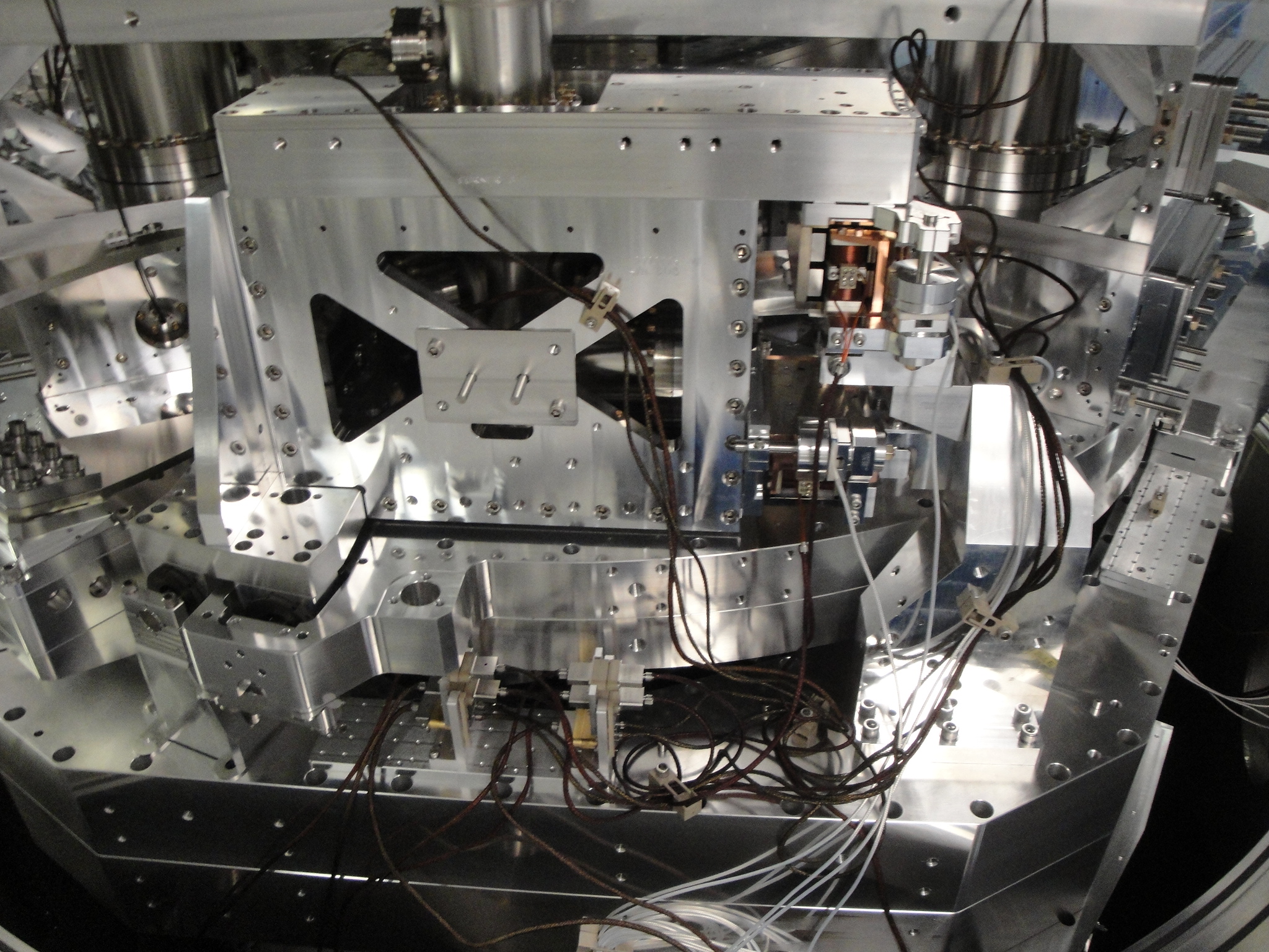
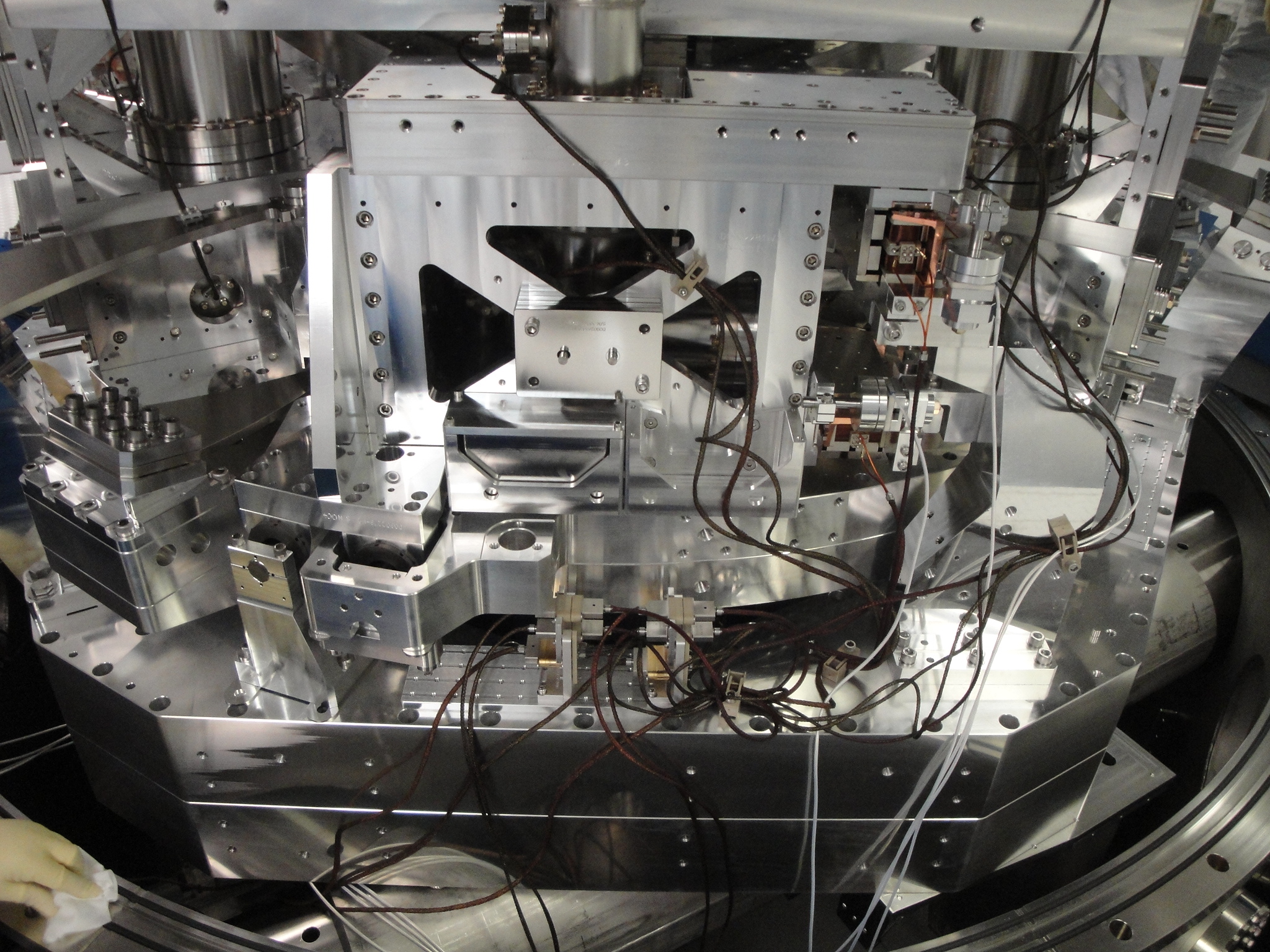
After the HAM3 cleanroom was pushed as far north as possible, the curtains were modified to closely interface with BSC2 and provide clean space for the spool replacement. The small spool piece was inserted  and attached to the BSC2 flange. Next, the large spool piece was inserted and attached to the small spool piece. The large spool piece is very close to the HAM3 flange. Once the hard cover on the spool piece and the soft cover on HAM3 are removed, the bellows will be extended so that the spool is married to the chamber. I expect that all spool and appropriate flange bolts will be torqued before the Apollo crew leaves for the day. That gets us through #11 on the checklist.

1.	Done-Remove Walking Plates from BSC 2 (Place in E-Mod Staging Cleanroom)
2.	Done-Replace dome on BSC2 (Check with SEI first: unlock ISI check cables)
3.	Done-Place hard cover on BSC2/HAM3 spool openings
4.	Done-Install curtains on HAM3 cleanroom
5.	Done-Move BSC cleanroom to beamtube by East Bay pipe bridge
6.	Done-Dis-assemble Work Platform (Place on floor by BSC7)
7.	Done-Move HAM3 cleanroom north as far as possible
8.	Done-Close gaps in cleanroom to contain BSC2 spool area
9.	Done-Move SEI related electronics over center of spool area
10.	Done-Insert small spool piece
11.	Done-Insert large spool piece
12.	Install HAM3 east door
13.	Move cleanroom from pipe bridge area to HAM4-plug in-turn on
14.	Call for HAM4 cleaning
15.	Install HAM2/1 east doors
16.	Install HAM 2/3 west doors
17.	Install BSC1 viewports
18.	Remove HAM4 north door
19.	Install blank on septum plate between BSC2 and HAM4
20.	Install HAM4 north door


Everything came back up fine as far as I could tell. Servos are all locked. I updated the safe.snap files as well.