sheila.dwyer@LIGO.ORG - posted 08:48, Thursday 14 March 2013 (5790)
h1ecatex
crashed last night
crashed last night
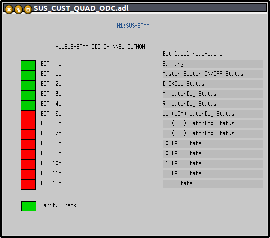
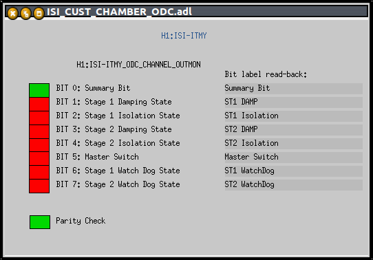
Ryan Fisher, Jeff Kissel, Stefan Ballmer

We started added the epics bit label strings to the ODC medm screen. Ultimately these strings are intended to be initialized my the front end model to keep track of long-term ODC bit assignment changes. For now we populated them by hand (see Ryan's elog).

So far we modified the medm screens for the BSCISI (BSCISI/ISI_CUST_CHAMBER_ODC.adl) and added the SUS quads (SUS_CUST_QUAD_ODC.adl). For the quads we modified the OVERVIEW screen to include a button to the ODC screen, and reduced the number of ODC bit indicators to the bits 0 to 12 that are currently used.

Many more screens need to be done: SUS triples and auxiliaries, HAMISI and HEPI.
Ryan Fisher, Stefan Ballmer

We have set the EPICS records for the labels that describe the ODC bits for the SUS and ISI models currently running in H1.*  The labels provide a short description of what every bit in each ODC channel represents, for each ODC channel.  The higher order bits in the ODC channels that do not have labels are currently unused, but may be used in the future.

These records were set using scripts located in /ligo/home/ryan.fisher, and attached to this entry.

* Excluding H1:SUS-TMSY_ODC_BIT* for now.
I have now also set all of the EPICS strings that describe the bits in the ODC channels for the HPI models. The script is attached.
I have now also set all of the EPICS strings that describe the bits in the ODC channels for the TMSY model.  The script is attached.

Note that there is a small bug in the models for these channels that currently mislabels bit4 as bit6:
H1:SUS-TMSY_ODC_BIT6
(should be H1:SUS-TMSY_ODC_BIT4)

We will go through the process of changing this small bug in the corresponding Simulink model library part, after emailing cds_announce and sus team members.
I added scripts for setting the ODC bit labels and masks in /opt/rtcds/userapps/release/cds/h1/scripts

h1setODCbitmask:    Set ODC bit masks for HPI, ISI and SUS
h1setODCbitstrings: Set ODC bit labels for HPI, ISI and SUS
Correction to scripts included above:

The ISI-HAM ODC channels should only have 5 bits, and should not be part of the other ISI channel script.  The corrected scripts are attached, and the correct scripts are in the following location on llocds.ligo-wa.caltech.edu:

/ligo/home/ryan.fisher/EPICS_Scripts
I corrected a small typo (M2 where it should have been M1) in SUS_OMC_Labels.txt for this log book entry only. The scripts in /ligo/home/ryan.fisher were corrected approximately a month ago. The corrected txt file is attached.
Attached are plots of dust counts > .3 microns and > .5 microns in particles per cubic foot requested from March 13 00:00 UTC to March 14 00:00 UTC. Also attached are plots of the modes to show when they were running/acquiring data.

Data was taken from h1nds1.
T0=13-03-13-00-00-00; Length=86400 (s)
1440.0 minutes of trend displayed

'No data output' error on > .3 micron plots.

I forgot that the dust monitor at end X had been removed from the edcu, so the data has not been saved since I turned it back on this morning.
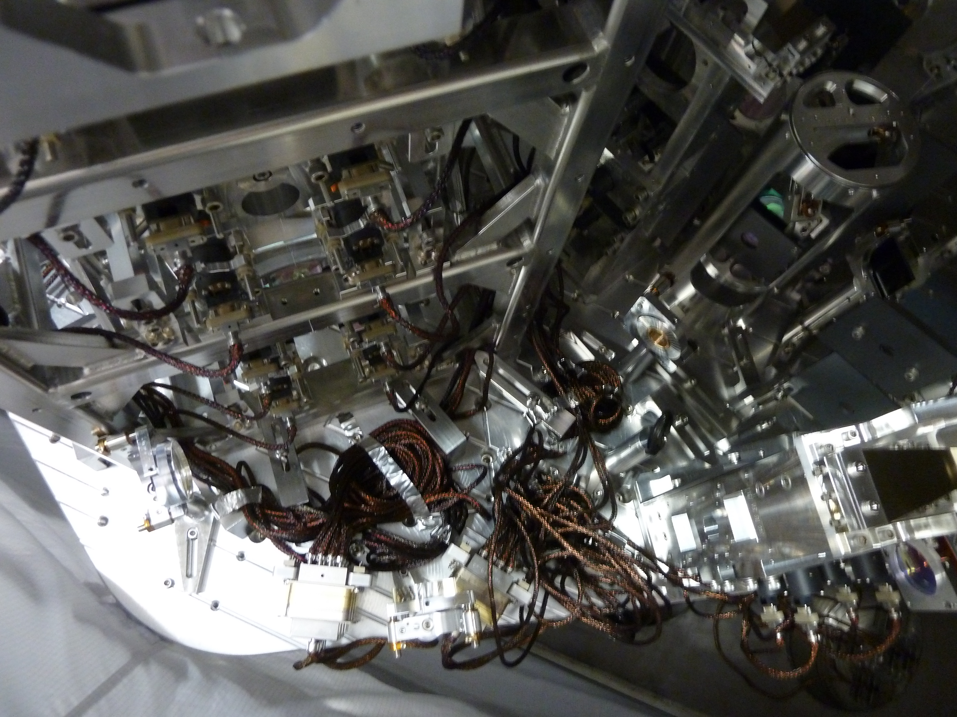
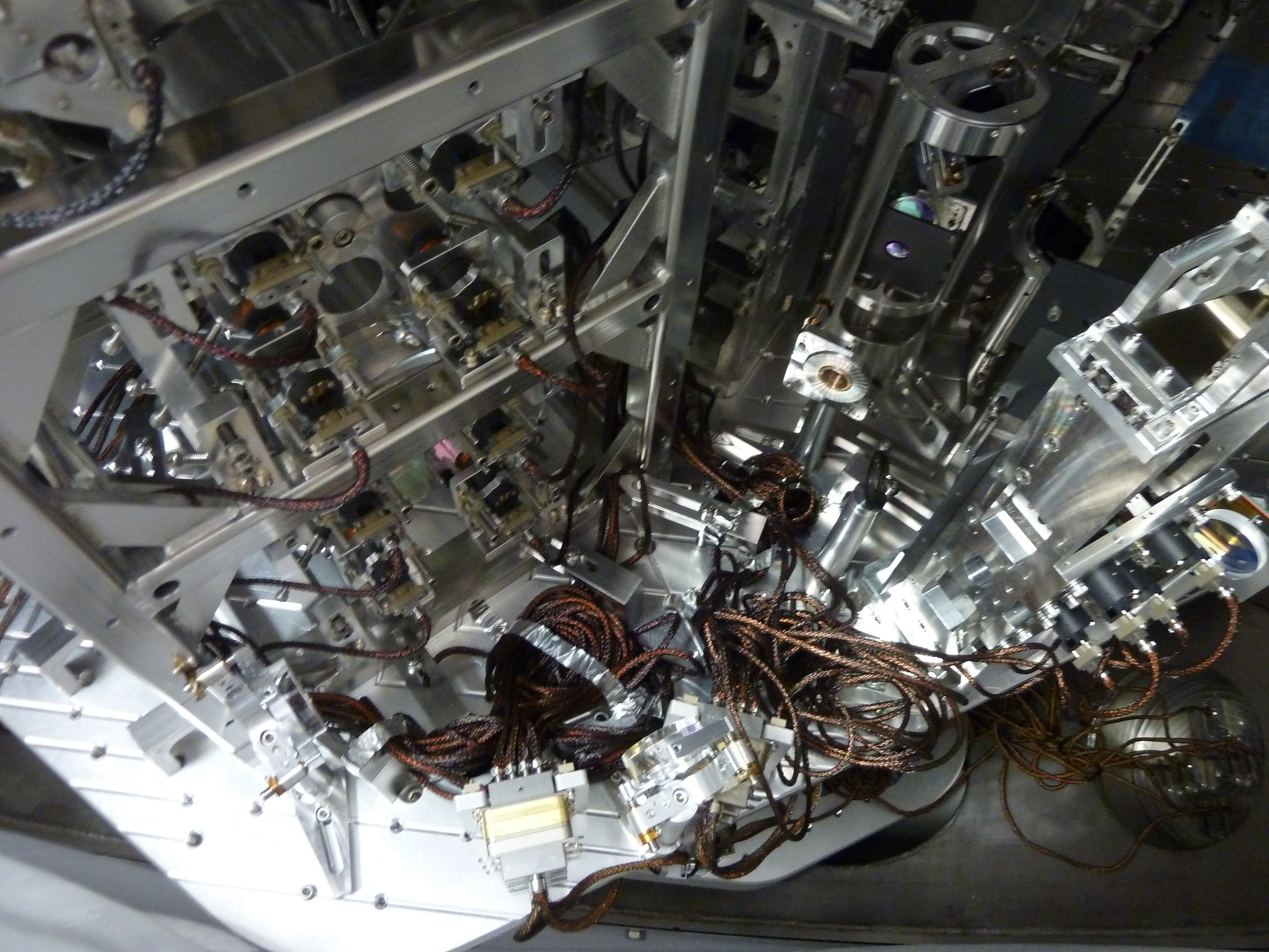
[Deepak K., Rodica M., Chris M.]

Tasks Accomplished:
* Realigned MC Refl beam through the periscopes.  It was off center on some of the baffles by 1/2 a beam diameter.
* Tweaked the alignment of the beam through the Faraday. It was reasonably well aligned already, but we made a small adjustment to IM1.
* Implemented Rodica's brilliant idea to reroute the MC Refl beam to overlap with the main beam.  We did so by using two eLIGO steering mirrors and injecting at MC3 (see pictures).  This gives us the full ~180 mW of power downstream of the IMC to align auxiliary beams.
* Installed the HWP in the rerouted MC Refl beam to correct the funky polarization.

Notes:
* The first hard aperture(HA1) needs to be recentered after the clamp issue is fixed.  (It has a large dog clamp).
* The AOEs are missing their second SiC baffles still.  Recheck the centering after the baffle is installed.
* We removed MC3 AR Baffle and placed it in front of MC3.
* We borrowed the HWP from the main beam line to correct the polarization of the rerouted MC Refl beam.
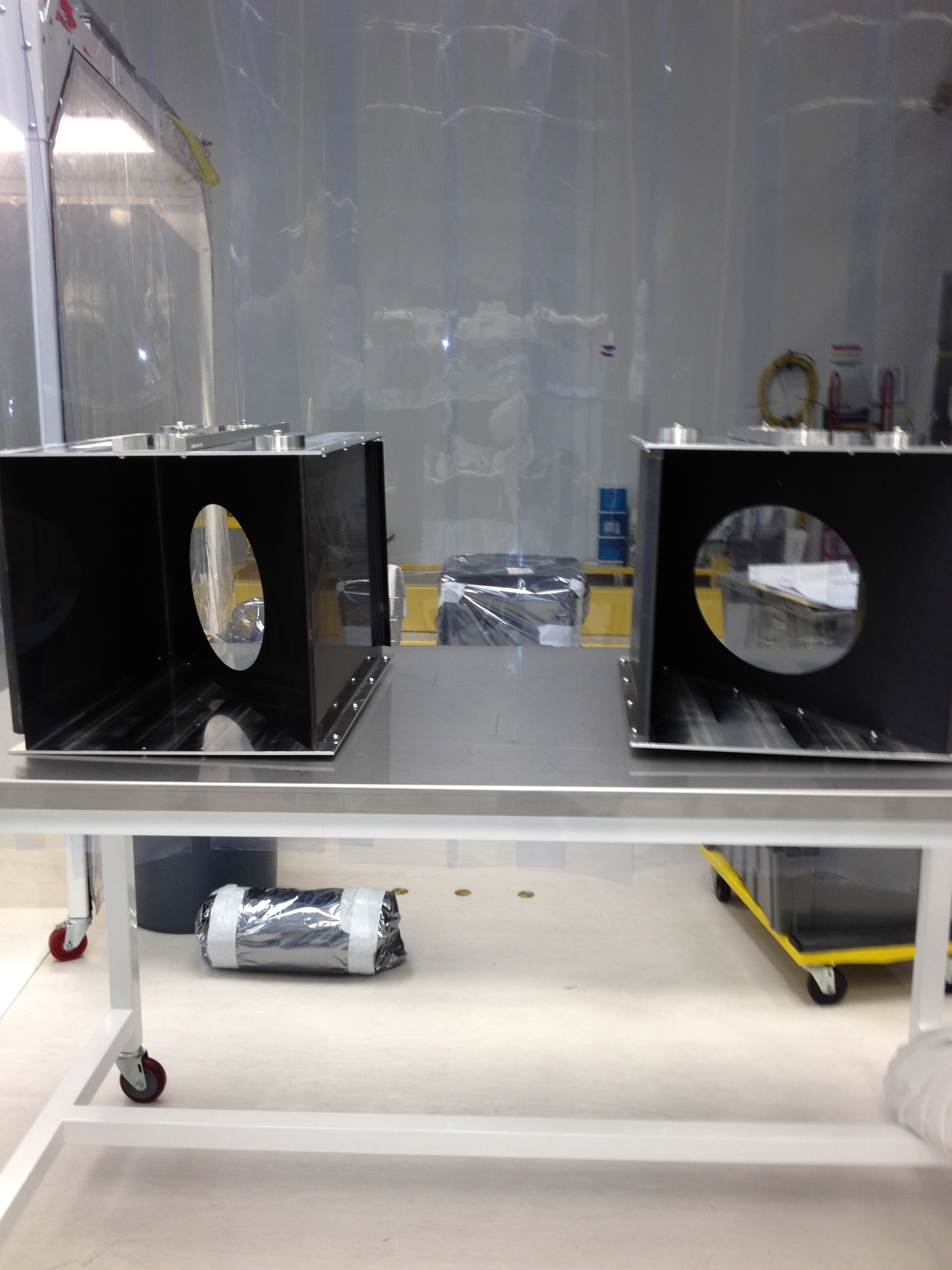
Mick (Apollo), Thomas V

We've completed building the boxes per E1200667-V4.  No mishaps, picture attached.
Tomorrow we will measure the PRM vertical position error, make any shifts of the PRM that are required, and then move on to PR3 pitch/yaw alignment.
- 12:00 water sampling
- no safety meeting
- Patrick turn on DUST EX monitor
- PSL ENV alarms were on, and still on, for several days
- EY laser hazard
- Rick gave T.K. Machine's crew a tour
13:30 LSB
15:00 - 15:20 LVEA
15:25 roof
- Dave and me with Ski consent, changed the MAX value of the channels
H0:FMC-MX_AH_COOLTEMP_1_DEGF
H0:FMC-MX_AH_COOLTEMP_2_DEGF
from 75F to 80F
- 16:30 LVEA transition to laser hazard
Today I vented X-end -> An Apollo crew (Mark L., Chris, Scott) removed BSC5's dome and found an insect on the underside of the outer O-ring at the exact point that I had marked as the leak location -> They lifted up this portion of the outer O-ring +/- 1' in either direction, removed the offending insect and wiped down the O-ring with an alcohol wipe -> During an overall visual inspection they also noticed a cut "sliver" of O-ring at a non-leaking location but this cut was not on the portion of the O-ring that comes in contact with the sealing surface and they left it be -> I pumped down the annulus volume following the dome's re-installation and helium leak tested only the area addressed -> No response (1 x 10⁻⁸ torr*l/sec baseline) -> This is encouraging but inconclusive as new leaks may have resulted from the dome's removal/installation -> I'll know more tomorrow.
J. Kissel

With the TMS in it's current rubbing state, it's difficult to properly model any damping loop design based on the measured transfer functions -- and as you know, we don't yet have a dynamical model that we trust to design on instead. But, I did so anyways, and discovered that the loops really just needed their gains adjusted. Some degrees of freedom had no open loop gain above unity, others had way way way to much open loop gain, and were just down-right unstable.

Here're the changes to the damping loops:
(1) Included a "from_um" or "from_urad," which takes out the "to_um" calibration of the sensors, so we can stick with the otherwise-normalized filter design. These are in FM5, like every other type of the suspension (which is usually poorly named "norm").
(2) Turned the ELF10 elliptic filter back on, as was the original design intent.
(3) Changed the gains from [L,T,V,R,P,Y] = [-20.0; -7.0; -10.0; -20.0; -5.0; -5.0] to [-20.0; -10.0; -20.0; -0.05; -0.5; -0.1]. (These new gains are also now roughly consistent with the ratios between DC magnitude (i.e. the stiffness) what's seen in the transfer functions).

I attach the modeled open loop gain and suppression for each degree of freedom with the new gains I've installed. Note, I intentionally removed the phase subplot because the data is so noisy / incoherent, I couldn't trust anything regarding phase margins, and flew by the seat of the modeled closed loop gain and suppression magnitude to help me determine where the stability regions lie.

If you're interested in using the scripts to make these plots in the future, they live in
${SusSVN}/sus/trunk/TMTS/Common/FilterDesign/
design_damping_L_TMTS_20130313.m
design_damping_P_TMTS_20130313.m
design_damping_R_TMTS_20130313.m
design_damping_T_TMTS_20130313.m
design_damping_V_TMTS_20130313.m
design_damping_Y_TMTS_20130313.m
J. Kissel, (for K. Kawabe, K. Izumi, and T. Sadecki)

Team TMS + Travis ventured down to the y-end this morning in hopes to discover some obvious source of rubbing, which I'd reported a few days ago (see LHO aLOG 5768). Unfortunately, they didn't find anything. They did adjust the alignment/centering on a few of the BOSEMs (they didn't say which), because only because they looked suspicious. I've taken a new set of transfer functions, and I see little to no change. The best "improvement" is that the three Transverse modes look more like the model -- but the model still comes with many grains of big'ol kosher salt, and the high-frequency noise (for this DOF) looks much worse. I'll continue to push forward on a "new" damping loop design (more likely I'll just model the damping with the measured TFs, asses where things are going unstable, and move around some poles or zeros if need be), in parallel with further investigations of rubbing.

Note: Mark made some improvements to the model this morning -- mostly related to making sure the coordinate system is as expected by the model (it's a whole confusing mess between the SolidWorks XYZ, the Dynamical Model's XYZ, and the Euler Control Basis -- especially since the top mass is the same as a QUAD top mass but rotated 90 [deg] with respect to Dynamical Model expects. Not to mention left-handed vs. right-handed TMTSs). We *think* we've got them correct at the moment, but the only way we can be sure is by opening up SolidWorks and checking (where Mark and I only have the eDrawings).
Thanks, Jeff. The BOSEMs that Travis adjusted were : two top OSEMs and side OSEM.
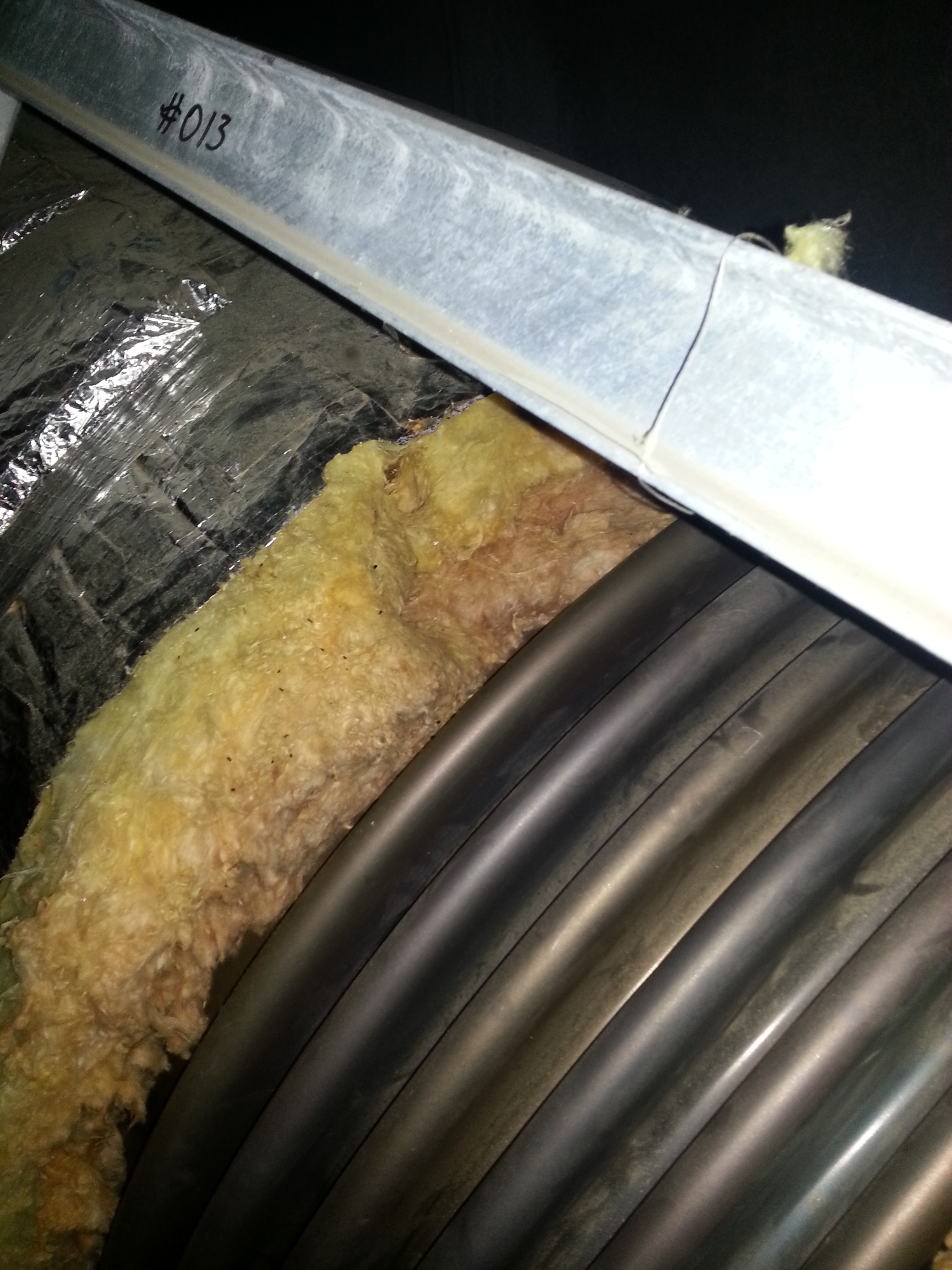
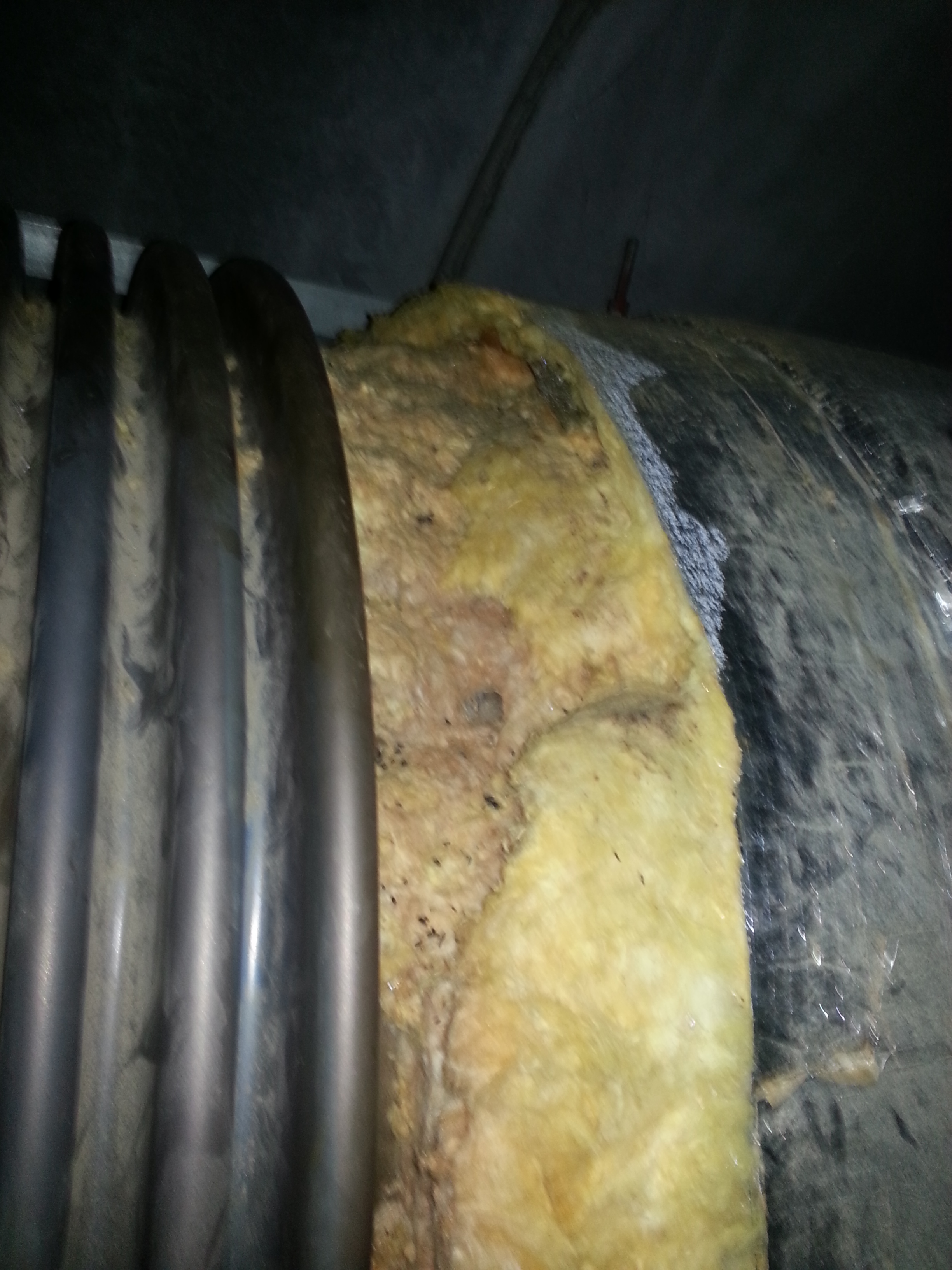
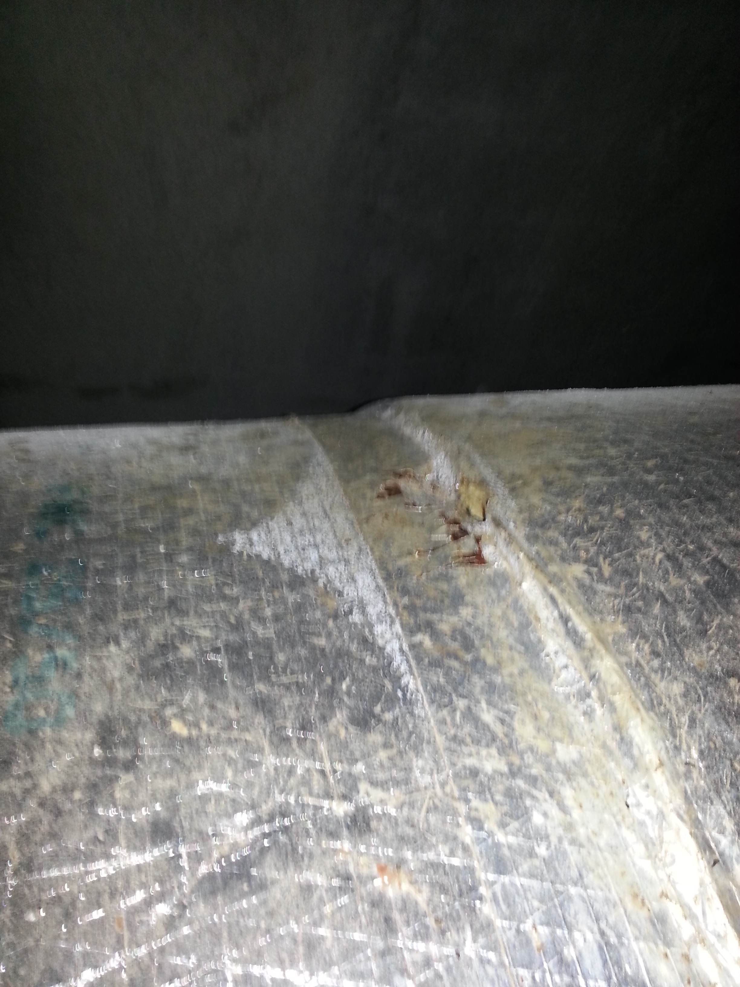
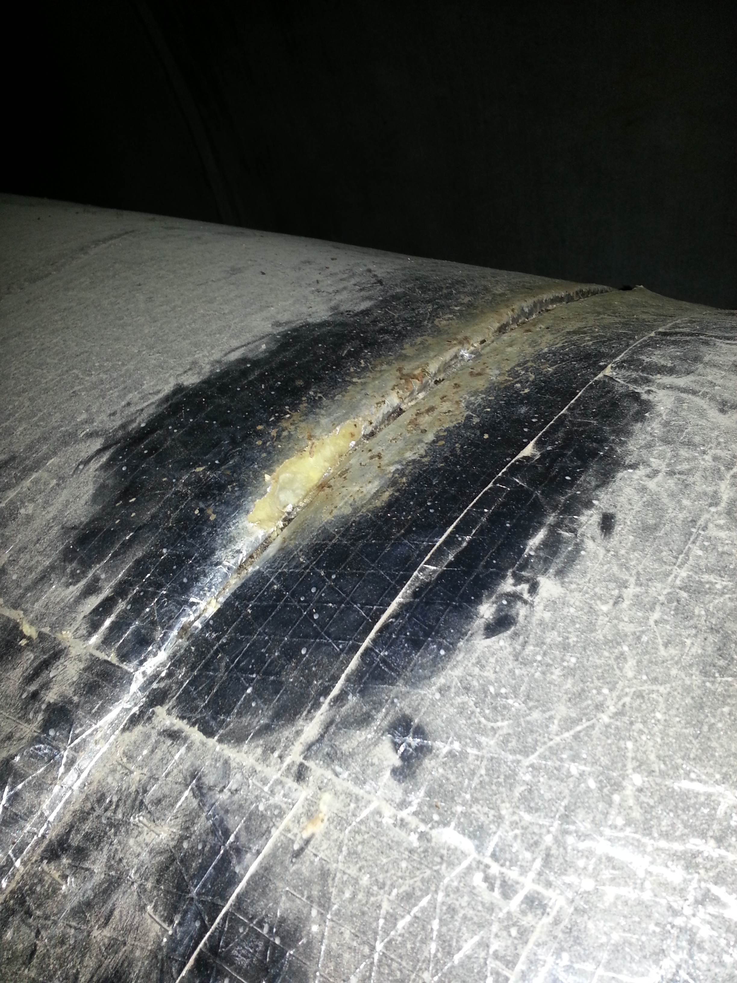
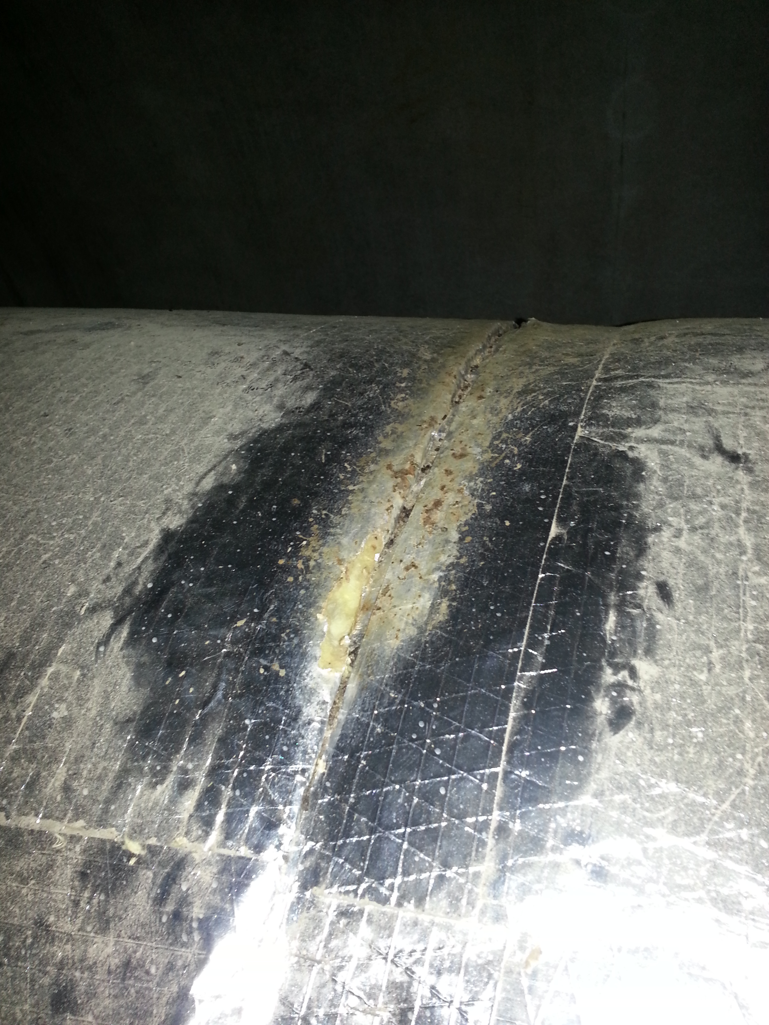
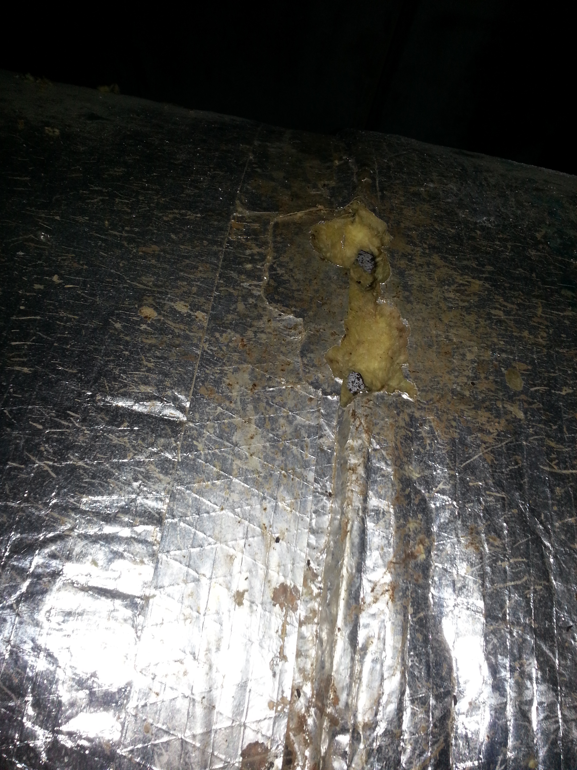
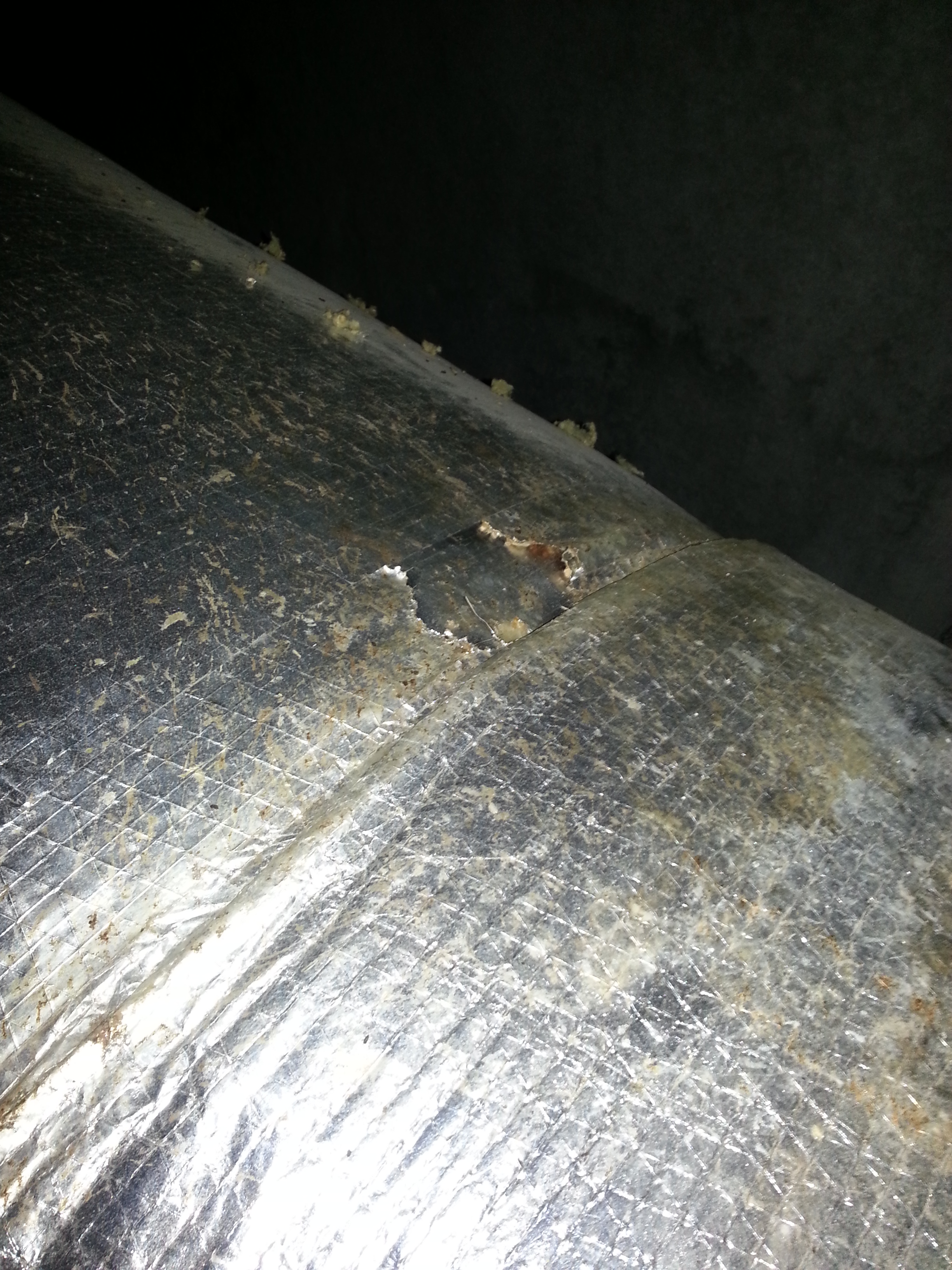
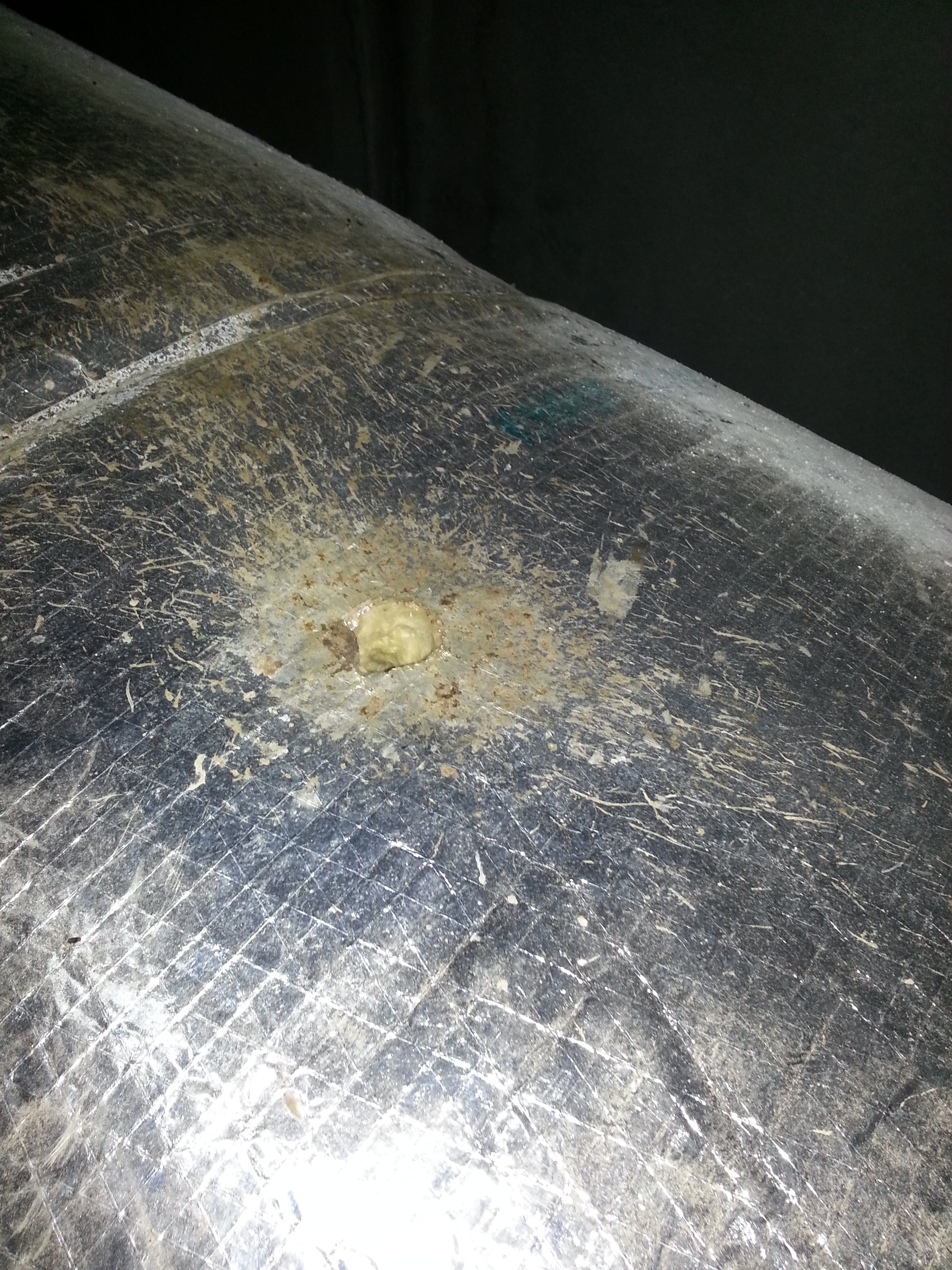
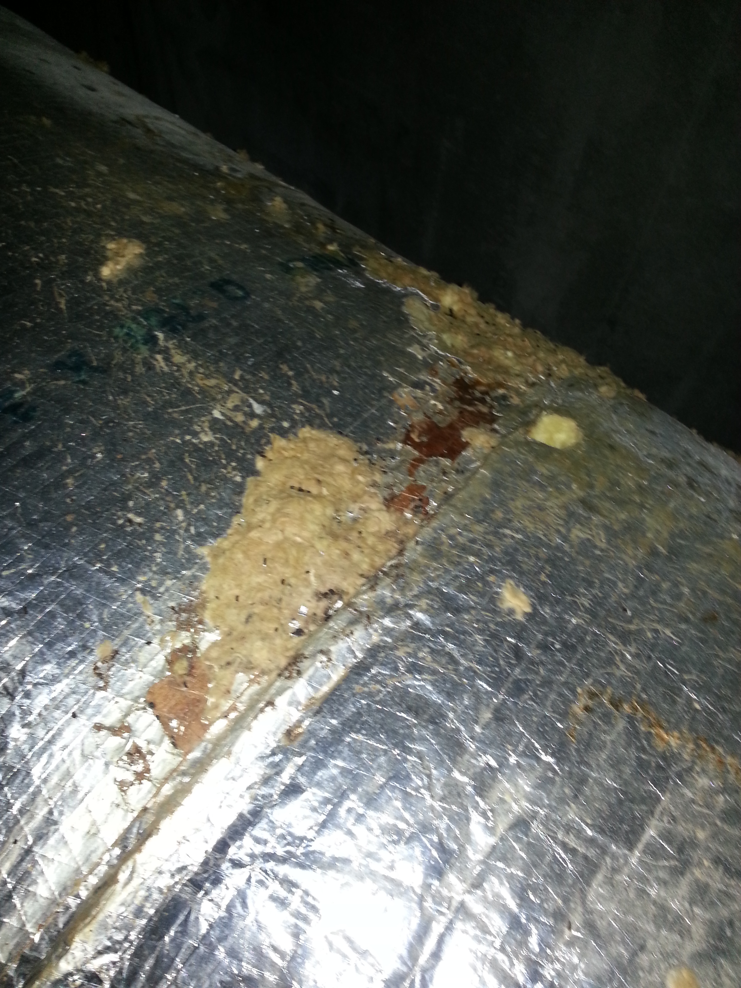
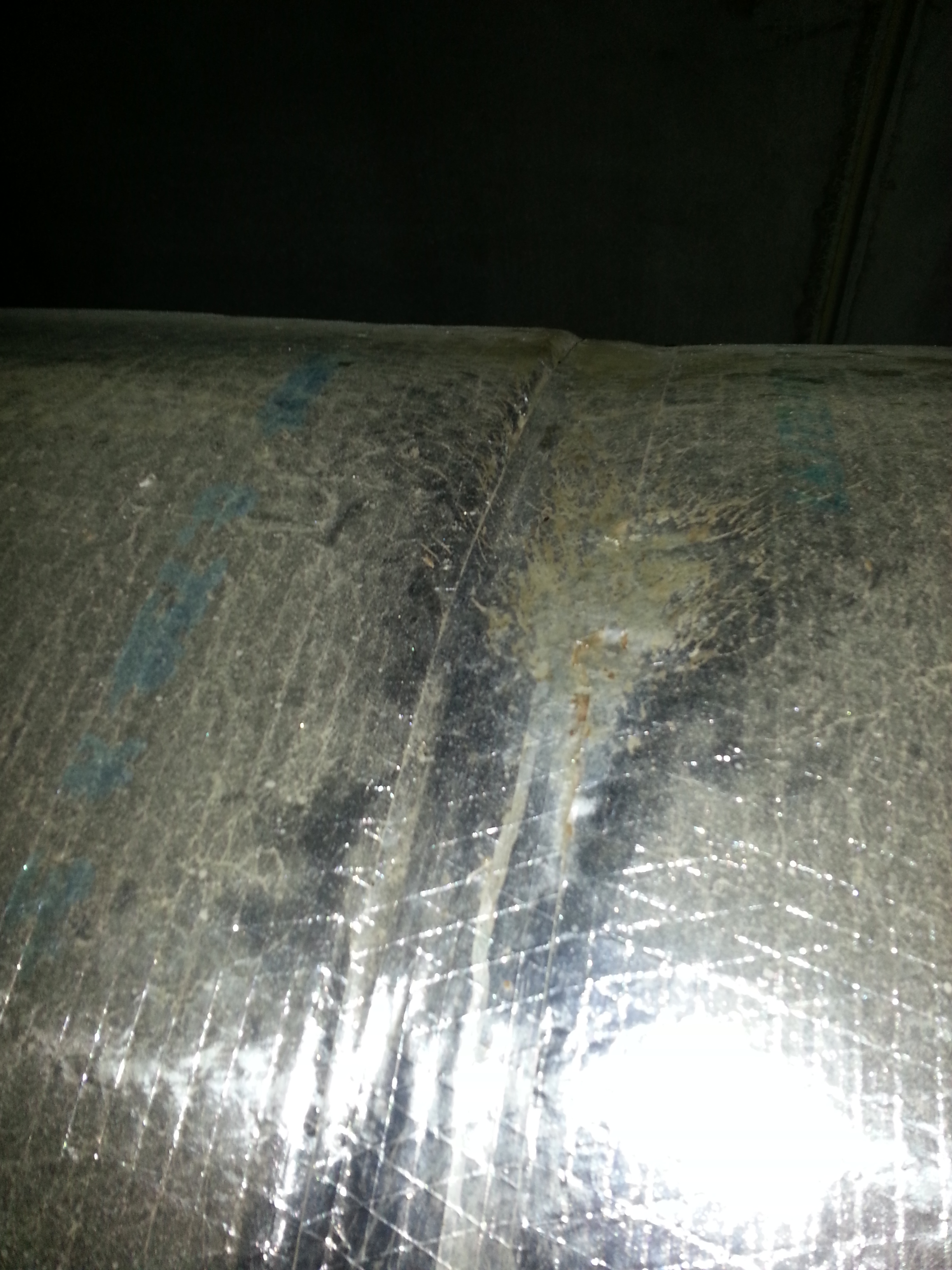
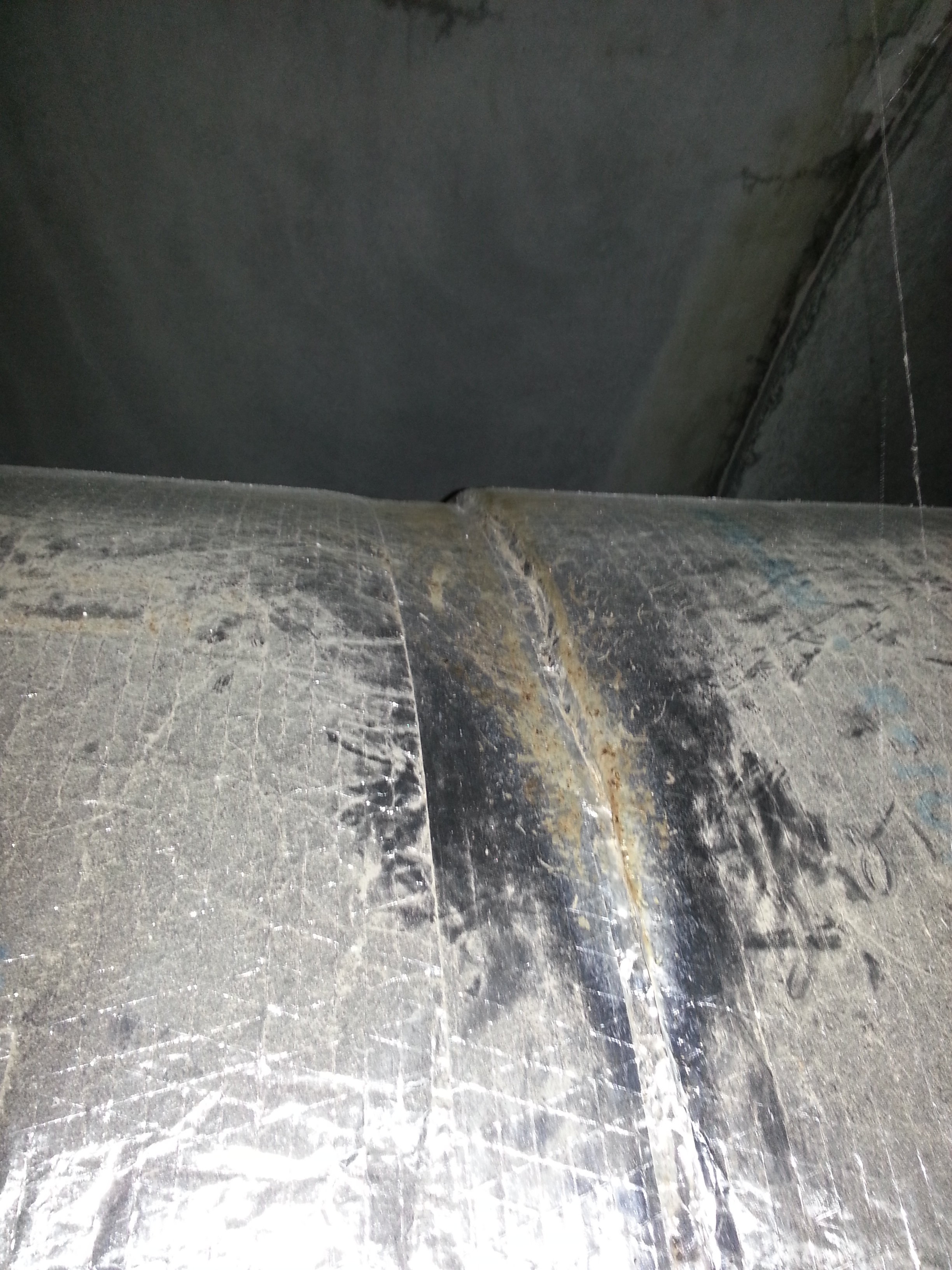
I walked about 300 meters of Y1 this week and took some photos of the beam tube insulation.
Between ports 2 and 3 (a distance of 250m) I counted 35 holes in the insulation. Virtually all of these holes were at taped joints between insulation wraps. These joints occur every 4 feet.
So of 800 taped joints I saw 35 which were violated by rodents. There may have been a few more on the backside of the tube. The photos in this report show some of the holes, some of the "good" taped joints, and some views of the uninsulated bellows regions.
Thursday I looked into X1 and X2 (but not Y2) specifically to see if the bellows are insulated. It looks like they are so Y1 may be unique in this regard. However, the insulation is pretty ragged and will need to be scrapped.
PR2 (installed in HAM3 chamber) power spectra have been taken after yesterday's gross alignment.
The figures attached show a comparison for PR2 damped and undamped between :
-LLO Phase 3a (Mai 2012) purge-air off, ham3 door closed
-LHO Phase 3a (October 2012) ham3 doors open and covers on
-LHO Phase 3a (March 2012) ham3 doors open covers off with M2 and M3 OSEM out
Looking at M1 DOFs of the undamped spectra, the resonnances are consistent with LLO and LHO previous measurements.
An other spectra will be taken after the fine alignment.
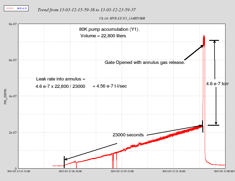
After performing another accumulation on Y1 with CP1 isolated from the tube we think we have found our leak. It looks like the annulus of the gate seal has a leak into the system.
This was highlighted when we reopened GV6 after the accumulation.
So in summary the outgassing from Y1 appears to be in line with the 3 other modules, the CP1 outgassing rate is reasonable and we have a leak to follow up on.
SUMMARY:
LHO Module Total Outgassing Outgas rate/unit area Hydrogen Date Outdoor Temps Post Bake(1998) H2 at 23C at 0C
torr- l/sec torr-l/s/cm^2 torr-l/s/cm^2 high/low C torr-l/s/cm^2
Y1* 5 e-7 6.8 e-15 1.7 e-14 Mar 12 16/4 6.3 e-14 9.0 e-15
Y2 2.4 e-7 3.3 e-15 8.25 e-15 Mar 6 5/1.1 4.7 e-14 6.8 e-15
X1 5.4 e-7 7.3 e-15 1.83 e-14 Mar 7 12.2/3.3 5.2 e-14 7.4 e-15
X2 3.4 e-7 4.6 e-15 1.2 e-14 Mar 8 12.2/1.1 4.6 e-14 6.6 e-15
Volume of each module ~ 2.35 e6 liters
Area of each module ~ 7.35 e7 cm^2 (excludes baffles and port hardware)
Gauge factor for cold cathode and H2 = 2.5
Note that each module accumulation includes the 80k pumps at either end - a significant surface area of untreated SS with H2 outgassing of perhaps 100x that of the beam tube steel(per unit area).
Y1 result is estimated from the sum of two accumulations(tube + CP1) performed on Mar 12.
NOTE: If you subtract the outgassing due to CP1 or CP2 from the Y1 and X1 results you will get numbers much closer to the Y2 and X2 modules. The measured outgassing from CP1 is 2.3 e-7 tl/s.
Seems like the problem we had when using a green beam reflected off of a 50-50 IR beam splitter was because of the fact that 50-50 surface for 1064nm works as a very good AR for 532nm.
The BS in question is this: https://dcc.ligo.org/LIGO-E1000671-v1
Corey used a fiber coupled green laser as the source, placed a PBS cube for 532nm to ensure that the P-pol light is transmitted, and used a HWP for 532nm to change the polarization.
There are two beams in reflection, one from 50-50 IR BS surface and one from the back surface. There is one beam spot in transmission, because the 50-50 IR BS surface is very small. Anyway:
| P-pol | S-pol | |
| 50-50 IR surface reflection | 0.92% | 0.044% |
| AR surface reflection | 6.3% | 20.7% |
| Transmission | 92% | 79% |
On TMS ISC table (and in the arms) the green light has S-polarization, and according to Corey's measurement we're totally screwed.
Now that we know about this, we could either align the red QPD path assuming that there is an invisible beam next to a visible beam at a known distance, or we could place a HWP on the ALS table and inject a wrong polarized beam to see if we get anything.
Corey will write a one-page document and add it to E1000671.
Note added to E1000671v1 is here.
Attached are plots of dust counts > .3 microns and > .5 microns in particles per cubic foot requested from March 12 00:00 UTC to March 13 00:00 UTC. Also attached are plots of the modes to show when they were running/acquiring data.

Data was taken from h1nds1.
T0=13-03-12-00-00-00; Length=86400 (s)
4020 seconds worth of data was unavailable on this server
1440.0 minutes of trend displayed
Richard to end Y to look at seismometer
John to mid Y to close GV 10
Rebuild of h1susmc2 against unmodified 2.6.2 RCG code, restarted
LN2 CP7 fill
restarts of corner station PEM, DAQ restart
alignment work in HAM3
restart of mid X PEM, end Y PEM
Richard re-zeroed STS2 seismometer, removed tilt-meter from PEM at end Y
h1slow-cds gateway restarted
[Rodica M., Deepak K., Chris M.]

Today we resolved the issue with IM3 which turned out to be an earthquake stop rubbing.  It isn't clear how this became an issue after pumping down, perhaps it slipped in over time.  See the attached transfer functions for an idea of the badness and subsequent goodness.

After we were allowed to turn on the laser we double checked the centering on the IMC mirrors which seems very good to us.  We added an iris at MC2 to double check the 'by eye' centering which was done at the end of last week, and the beam looked very good.  We also installed the MC2 scraper baffle.

Tomorrow we will check the alignment of the components downstream of the IMC.  Afterwards we will align the MC refl beam onto the trans beam path and use it to align the auxiliary paths and measure mirror transmissivities.
The Dog clamps installed on the MC2 Scraper Baffle are
[Paul, Kiwamu, Keita, Dick, Rodica]
Today we measured the mode cleaner cavity length by modulating the EOM at 45 MHz and doing a sweep around this frequency. We measured the spectrum using an HP 43968 Spectrum Analyzer. The maximum source power was 19 dBm from a Mini-Circuits RF amplifyier with gain 19 dB. The bandwidth for the highest zoom on the peak was 300 Hz.
The frequency of the dip in the middle should correspond to the 5th FSR away from the carrier resonance. The calculated length is 9.09918 MHz +/- 100 Hz, only 291 Hz away from the design value of 9,099,471 Hz. This is equivalent to 1.05 mm difference from the design length.
We tried a full sweep over one FSR but we realized that the modulation away from resonance would be too small to give us any useful results, so we focused on the 45 MHz resonant peak. Attached is a plot of the data over a full FSR, that also shows a peak corresponding to the non-resonant polarization, and few other peaks possibly due to higer order modes.
Similar measurements at LLO are described in alog 4702.
Just to add some redundant information, the measured FSR of 9.09918MHz +-100Hz corresponds to:
half-roundtrip = 16.4736m+-0.2mm.

