cheryl.vorvick@LIGO.ORG - posted 22:40, Thursday 29 November 2012 (4802)
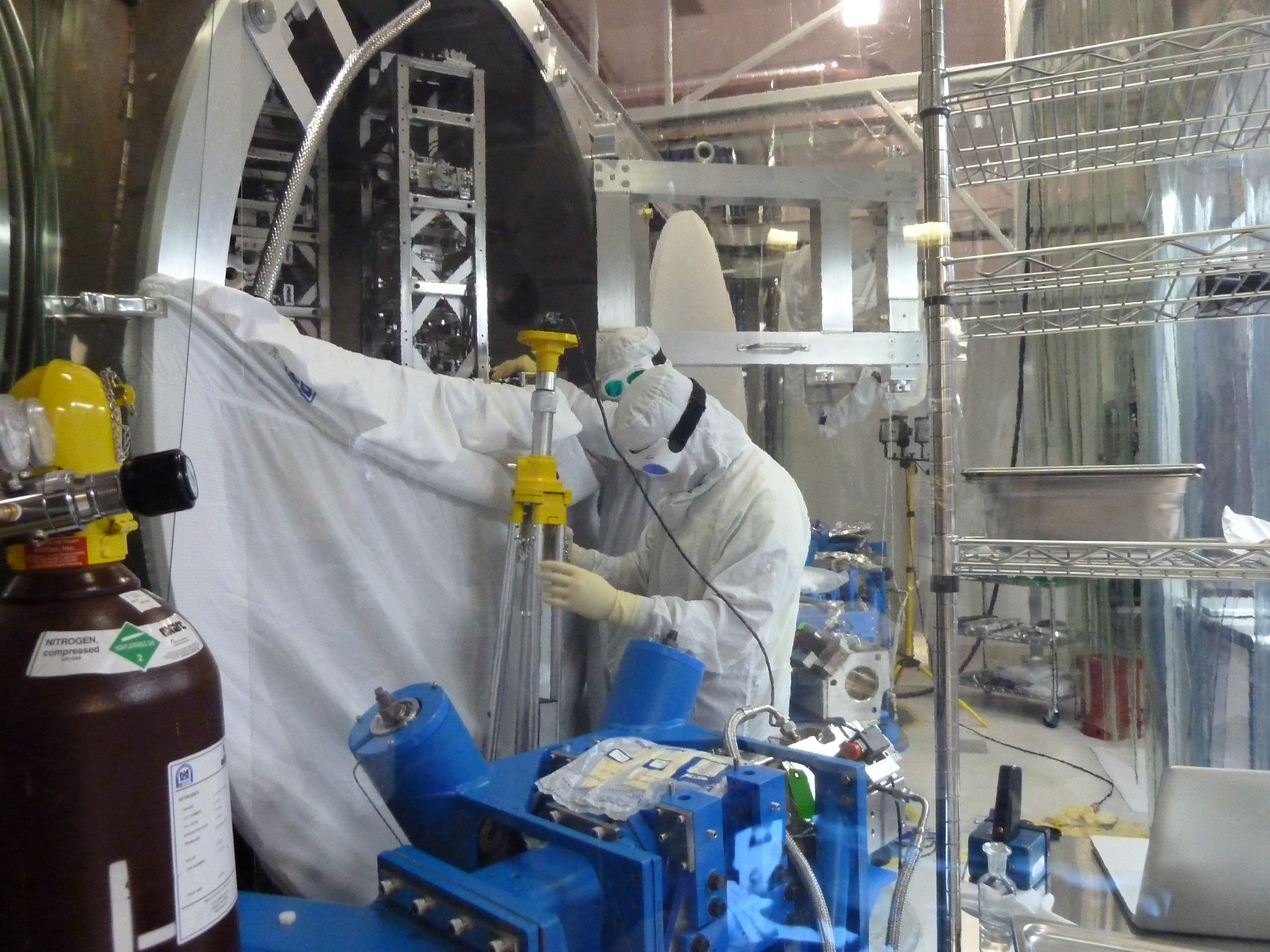
IO install and MC alignment: HAM2 vacuumed and wiped
- Chris, Giacomo, Rodica, Cheryl

IO:
Input beam to MC was aligned to the irises in front of MC1 and MC2.  MC1/3 were aligned to get the MC flashing.  Remaining two HAM Aux's had FC pulled and surface issues handled (left over FC and possibly others that Rodica can comment on).  The two HAM Aux'es that were moved for MC alignment were reinstalled using their alignment templates.

I put in an alog earlier today that lists the 2" optics that are installed in HAM2 in the IO periscope and steering mirrors AROM RH1 and ROM RH1.

HAM2:
The day began with Chris putting in most of the effort to vacuum and wipe  surfaces in HAM2.  Betsy and I found particulate on MC1's cage and throughout the chamber yesterday, and Rodica saw that the HAM Aux optics were populated with particulate pretty much as soon as FC was pulled.  I vacuumed MC3 and found particulate everywhere, both black and white flecks, and shinny (clearly metallic) flecks.

We have two silicon wafers on the HAM2 table to monitor particulate.  It's not clear to me now, that particulate that lands on these is necessarily particulate added to the chamber, because it seems possible that it could be particulate that's already there and just being moved around.