Displaying reports 84721-84740 of 88593.Go to page Start 4233 4234 4235 4236 4237 4238 4239 4240 4241 End
Reports until 19:19, Friday 24 August 2012
H2 ISC
keita.kawabe@LIGO.ORG - posted 19:19, Friday 24 August 2012 - last comment - 19:40, Friday 24 August 2012(3983)
WFS works (Alberto, Keita)

Assuming that the sensing matrix was correctly measured, from the filter shape it looked as if the UGF of WFSs were set to a mHz or two. This was because Alberto and Bram found that setting gain higher made things unstable.

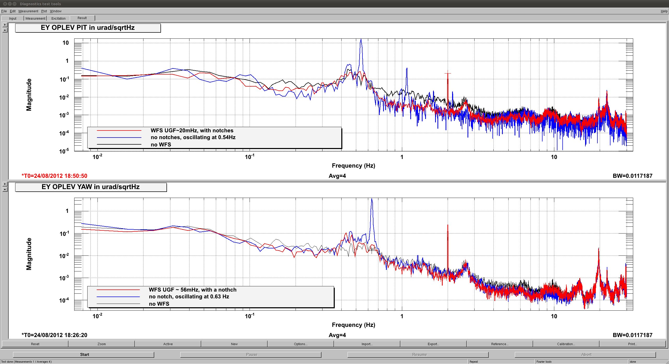
Today I and Alberto reproduced the problem by simply setting the UGF higher: Apparently 0.54Hz PIT mode and 0.64 Hz YAW mode goes unstable because of high Q (attached, glue traces).

The PIT mode number looks like it's in good agreement with JeffK's SUS resonance plots, though for YAW 0.64 Hz in our data looks more like 0.6Hz in JeffK's.

Anyway, I made some notches (0.54Hz and 0.44 Hz for PIT, 0.63 Hz for YAW) and brought the gain up by a factor of 10 or so and they didn't oscillate (red). With this setting, the UGF for PIT should be about 20 mHz and for YAW it should be about 55mHz.

I haven't tried to push anything further.

BTW 2Hz on the plot is caused by Robert's injection.
Images attached to this report
Comments related to this report
keita.kawabe@LIGO.ORG - 19:29, Friday 24 August 2012 (3985)

I and Bram briefly checked if things looks sane by giving an offset step to each DOF (ETM/ITM, PIT/YAW) one by one.

Each time, the feedback eventually brought everything back to where it should be, so it's OK.

Due to ETM - ITM servo coupling (remember, the servo is supposed to be diagonalized based on POS/ANG rather than ETM/ITM), when you kick one mirror there is an initial kick to both of the mirrors and eventually everything gets back to normal. Or it's supposed to be so.

For ITM step, the time constant for both the ITM and ETM to go back to the original angle looked about right.

For ETM step, for some reason the bulk of ETM step itself is removed almost instantaneously, and then ITM moves with what seems to be a right time constant while ETM goes through the same slow thing but with lesser amplitude.

Maybe the sensing matrix measurement was still far from nice. But anyway it works and I don't intend to fix that immediately.

keita.kawabe@LIGO.ORG - 19:40, Friday 24 August 2012 (3986)

Caution!

Now  WFS is with some useful oomph, which is good. However, this also means that, when the arm drops out of lock, WFS output might go big and the cavity might not be able to  relock on its own.

Though there are limiters to the WFS output (30 counts for PIT and 50 counts for YAW, which was set somewhat arbitrarily), 50 counts is large enough to tilt the mirrors such that 00 mode is really small in the cavity.

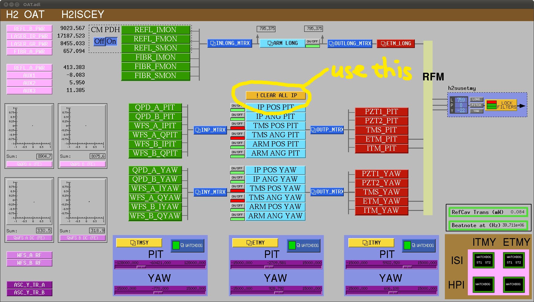
If this happens, you need to reset the integrator of the WFSs by pressing an ill-named "Clear all IP" button from H2 OAT medm screen (see attached) that is available from the ISC section of the sitemap.

If somebody writes an auto relocker that polls H2:ALS-Y_REFL_B_PWR_OUTPUT, disables CM PDH servo, press "Clear all IP" button and then enables CM PDH servo again, that would be greatly appreciated.
Images attached to this comment
H2 TCS
aidan.brooks@LIGO.ORG - posted 18:55, Friday 24 August 2012 (3982)
Ring heater cavity scan movie - LG10 mode

I did some analysis on the ring heater cavity scan measurements from yesterday. I've plotted the region around [0.37, 0.63] FSRs. This region encompasses the PDH TEM00 sideband resonances [0.45 FSRs and 0.55 FSRs] and also the LG10 sideband resonances. I've taken this section of data for each cavity scan and removed the constant phase offset and also the linear variation in phase with FSR. I've then plotted the scans as a movie. Despite the noise and the relatively quick speed, you can clearly see the response of a higher order mode shifting in frequency [0.53 FSRs to 0.58 FSRs] as time progresses. This is consistent with the cavity g-factor changing as the ring heater is applied.

I've yet to quantify the frequency shift.

Non-image files attached to this report
H1 AOS
thomas.vo@LIGO.ORG - posted 14:27, Friday 24 August 2012 - last comment - 15:26, Monday 27 August 2012(3980)
Output Mode Cleaner Baffle Assembly and Install
Lisa Austin, Rodney Haux, Scott (Apollo), Thomas Vo

We finished installing the aperture baffles for MCA2 and MCB2 this morning, and tightened up all the fasteners. This completes the entirety of our install for the output mode cleaner baffle.  

We were unable to screw in one button head cap screw on the MCA2 side due to alignment issues, pictures will be posted soon. Lisa Austin has documented this.
Comments related to this report
lisa.austin@LIGO.ORG - 09:04, Monday 27 August 2012 (3995)
On Thursday we chased the 3 tapped holes where there was resistance while in chamber with a clean #10-32 tap and cleaned/flushed with alcohol.

All hardware was attached, missing button head screw mentioned by Thomas Vo was installed.

Photos available on ResourceSpace at https://ligoimages.mit.edu/?c=1139&k=98338475ad
douglas.daniel@LIGO.ORG - 15:26, Monday 27 August 2012 (4001)
It was noticed that the 10-32 holes that needed to be chased with a tap, had inadequate countersinks at the top of the holes for easy lead in and centering of screw installation. 
LHO General
corey.gray@LIGO.ORG - posted 13:38, Friday 24 August 2012 (3974)
Day Shift Summary

8:15 - 1:30pm Activities (Thomas relieving for end of shift)

Morning Activities:  Installing 3 doors, & heating tests for OAT

LHO General
kyle.ryan@LIGO.ORG - posted 13:33, Friday 24 August 2012 (3979)
Kyle, Bubba - ~1325 hrs. local -> bumped XBM with pipe we were carrying (noise logged for OAT quiet time?)


H2 SEI
vincent.lhuillier@LIGO.ORG - posted 12:22, Friday 24 August 2012 - last comment - 21:43, Sunday 26 August 2012(3978)
Sensor correction - HEPI BSC8

I have implemented the sensor correction at HEPI-BSC8. Sensor correction improves the isolation performances of the HEPI in the X, Y and Z directions. In attachment, spectra of the L4C installed in the HEPI boots are presented in different configurations:

There is no plots in the uncontrolled configuration (Robert S wants to keep the cavity locked).

Non-image files attached to this report
Comments related to this report
peter.fritschel@LIGO.ORG - 17:42, Friday 24 August 2012 (3981)

Ugh -- no units on the vertical scales. Noise at 1 Hz goes down from ~100 to ~10; wish I knew what that means.

vincent.lhuillier@LIGO.ORG - 21:43, Sunday 26 August 2012 (3991)

The spectra are measured before blending the L4Cs with the position sensors. The units are (nm/s)/sqrt(Hz) above 1Hz. To get the calibration in nm, you need to invert the idealized L4C (3 zeros at 0Hz and a pair of complex conjugate poles at 1Hz with a 45deg phase).

Even if there is no plots of the uncontrolled HEPI, the isolation provided by the controller without the sensor correction is visible in the blue curve (“V shape feature”). The isolation is defined by the blend filters (LP) of the position sensors (first segment of the “V” – Blend at 800mHz) and the super sensor suppression (second segment of the “V” – UGF at 10Hz).
When the STS-2 (ground) signal is added to the position sensors (sensor correction), it is like having a seismometer (STS-2) in the HEPI boot (TF from ground to top of the pier close to 1 below 10Hz). Now, the super sensor is an inertial sensor above 40mHz. With the sensor correction (red curves), the actual suppression follows the super sensor suppression. Consequently, the isolation improvement is visible in the 40mHz to 3 Hz frequency band.

H1 FMP
jodi.fauver@LIGO.ORG - posted 11:34, Friday 24 August 2012 (3977)
Prep for dirty work next week
Doors were returned to HAM2 East, HAM2 West and HAM3 West, in that order. The task was completed by 11:20 AM. We reported to the Control Room at the start of each door. The main crane was returned to the parking position. The forklift is sitting on the West side of HAM3.
H1 AOS
michael.rodruck@LIGO.ORG - posted 11:05, Friday 24 August 2012 (3976)
PMC window reflection

David and I measured the reflection off the PMC window as 1.7W. When we had the 35W laser running this beam was 100mW. The razor blade dump was warm to the touch.

H1 PSL
michael.rodruck@LIGO.ORG - posted 10:59, Friday 24 August 2012 (3975)
PSL plots

For the 200W beam

Note that the peak in the ISS at ~120Hz is back indicating noise eater noise. This is odd as I had already reset the noise eater once today and it already went back into oscillation.

After talking to Jan I left the PMC heater off. The temperature is still coming to equilibrium.

Non-image files attached to this report
H1 IOO
giacomo.ciani@LIGO.ORG - posted 08:58, Friday 24 August 2012 (3973)
HAUX build: finished! (almost)
[Giacomo, Deepak]

Owing to the invaluable help of Deepak and the support of a lot of people on- and off-site (thanks all for searching, investigating, procuring, shipping, etc.,..), HAUX build has gone smoothly and swiftly.

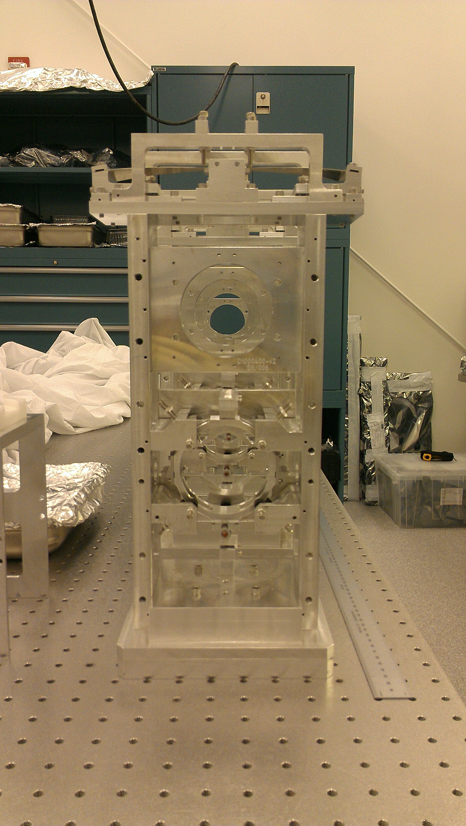
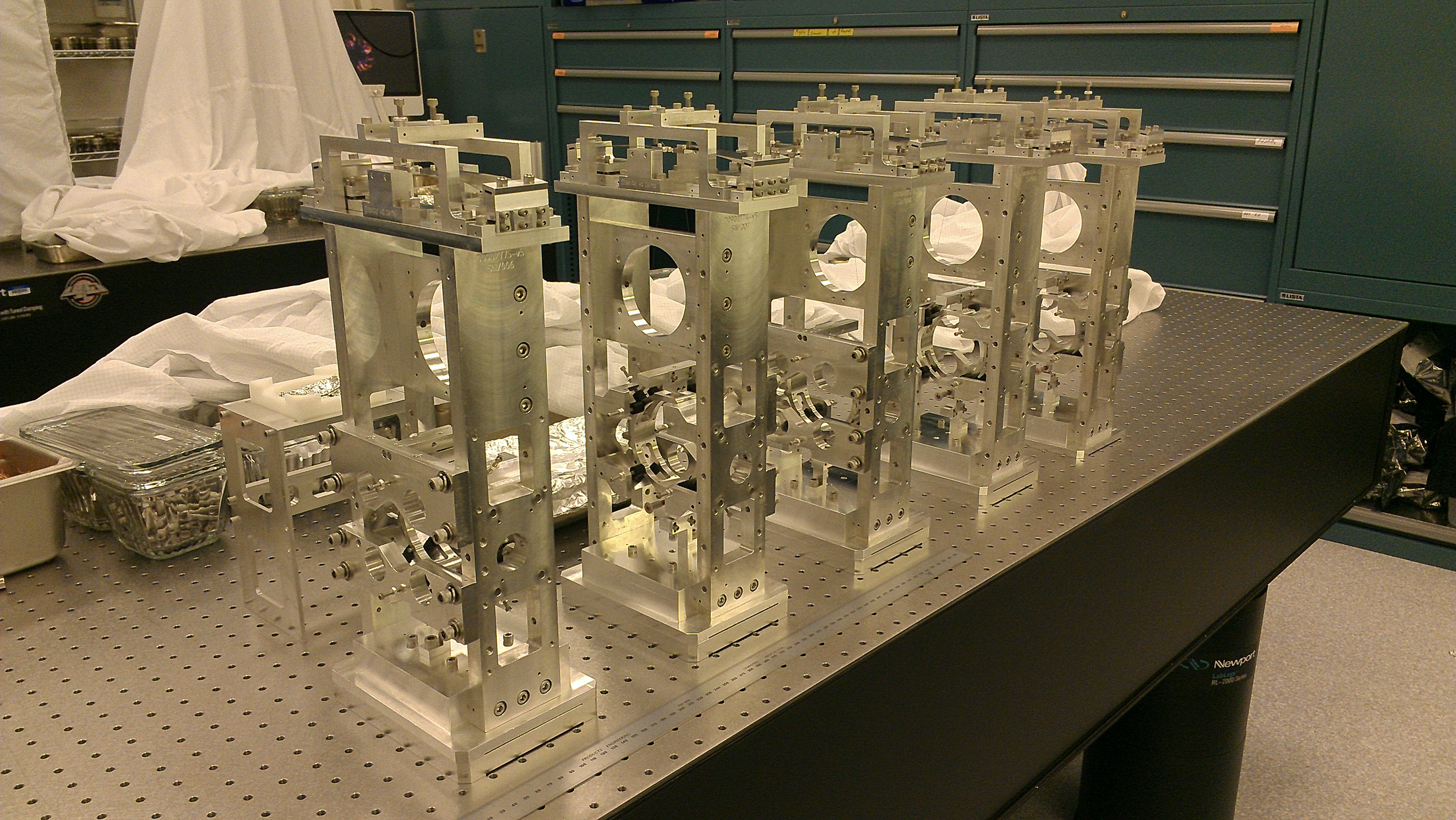
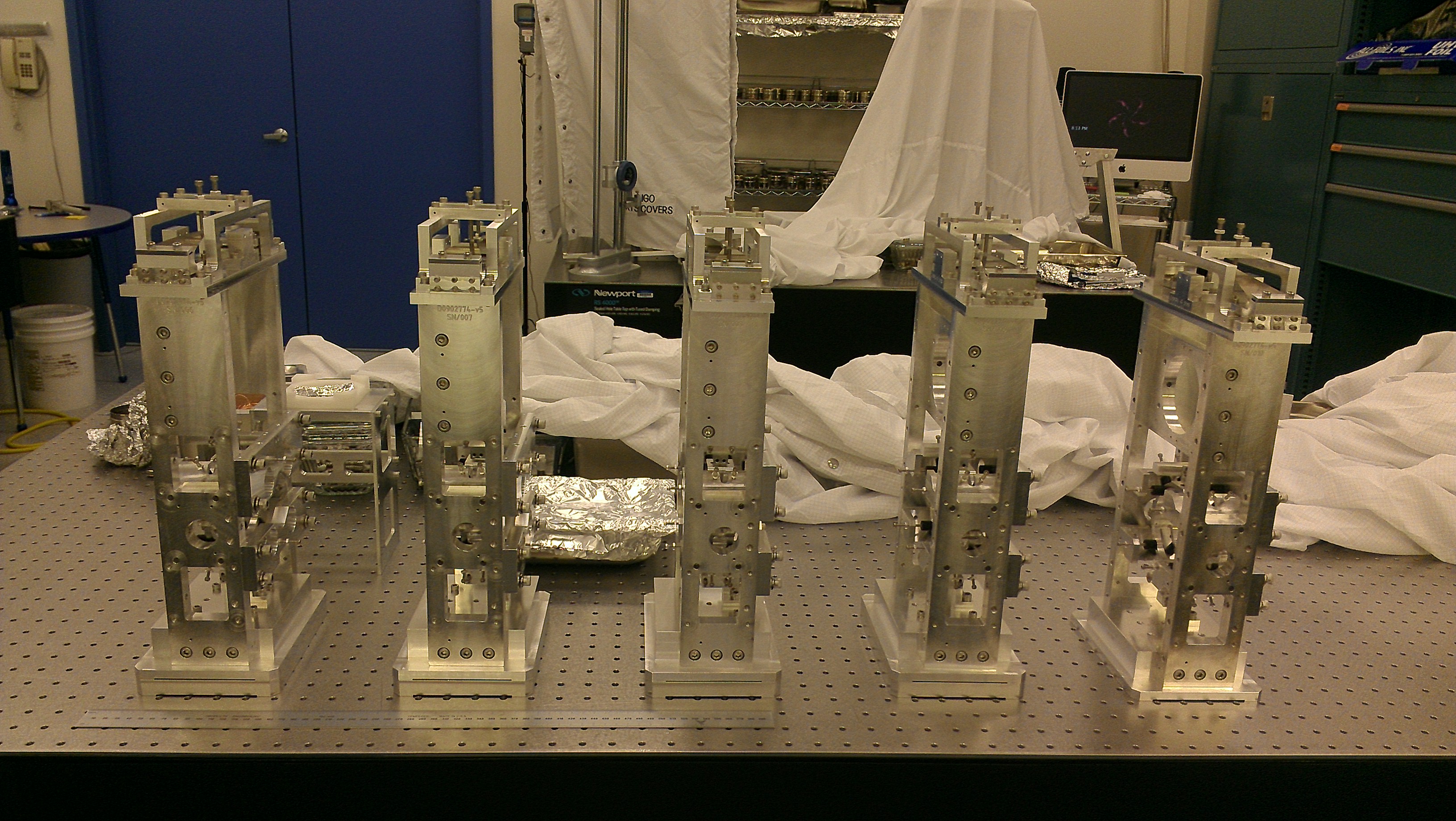
As of yesterday night, we have 5 complete suspensions, that you can admire in the attached pictures.

If you can't see the optics, it not because they are very clean: as they were not immediately available due to needed FirstContact work, we decided that the suspensions could be completed (including wiring) without the optics, and the optics added later (procedure in which we have been forced in the past to become experts). Because of that, we didn't even put in OSEMs and magnets. Altogether this would probably amount to another 1/2 to 1 hour of work per suspension.

The plan for today is probably to move the suspensions chamber-side, and then give priority to setting up electronics and cabling to exploit David Feldbaum experience (it's his last day here). After that's taken care of, we'll FC the optics, insert them and then proceed to the testing phase.
Images attached to this report
H1 IOO
david.feldbaum@LIGO.ORG - posted 20:12, Thursday 23 August 2012 (3959)
FI alignment in the H1 PSL

After Mike R. has transitioned to high-power operation I went ahead and aligned the FI with the CWPs, TGGs and Quartz. The straps for the magnet were not yet ready. Earlier I was not going to insert the TGGs into an unsecured magnet, however I decided that there is hardly any risk involved provided the platform is well secured in place.

To get a better CWP extinction ratio I had to get a better adjustible HWP rotator for the incoming beam. I found one in the PSL team's cabinet. With that:


CWP1 extinction
power p-pol power in s-pol extinction
3.8 W 19 µW 53.0 dB
50 W 0.36 mW 51.4 dB
100 W 0.70 mW 51.5 dB
125 W 0.85 mW 51.7 dB
20 W 0.12 mW 52.2 dB
Extinction with both CWPs
power p-pol power s-pol extinction
50 W 0.41 mW 50.9 dB
126 W 1.0 mW 51.0 dB
100 W 0.83 mW 50.8 dB
20 W 0.16 mW 51. 0 dB

Inserted Magnet with TGG+Quartz, polarization should rotate by 90 degree, p-pol should be minimized

power in power s-pol power p-pol extinction
8.99 W 8.92 W 0.42 mW 43.3 dB

Inserted the 2nd TGGs

power in power s-pol power p-pol Pin*sin^2(22.5 deg)
10 W 8.3 W 1.78 W 1.78 W
H1 SUS
betsy.weaver@LIGO.ORG - posted 18:51, Thursday 23 August 2012 (3972)
HAM3 installation arm removed

In prep for a few days of dirty cabling/EE work under/around HAM3/2, we removed the HAM installation arm from HAM3.  The arm will next be used on HAM2 in another week or two.  Bubba/Hugh/Mitchell (and maybe one or two others?) put the HAM3 East door on.  Tomorrow the other HAM3 and possibly both HAM2 doors will also go on.  Other notes about MC2/MC3:

Both MC2 and PR2 in-vacuum cables have been plugged in, completing all routing.  Signals are reading out in the appropriate medms. 

Grounding was checked and mitigated on in-vacuum MC2 and MC3 cables. 

B&K Hammer measurements were run on MC2.

MC2 has been left fully suspended, PR2 is locked however.

Cleanroom vacuums were tested chamberside.  Particle counter alarmed a few times, as expected.

LHO General
patrick.thomas@LIGO.ORG - posted 18:37, Thursday 23 August 2012 (3970)
plots of dust counts
Attached are plots of dust counts > .5 microns in particles per cubic foot.
Non-image files attached to this report
H2 AOS
thomas.vo@LIGO.ORG - posted 17:23, Thursday 23 August 2012 (3968)
Output Mode Cleaner Baffle Assembly and Install
Lisa Austin, Scott (Apollo), Nichole Washington, Thomas Vo

We chased a few holes in the viewport frame assemblies to give room around the top portion of the threads in order to give a bit more tolerance when installing the assemblies into the chamber.  We finished all four (two per baffle) today, yay! 

We also finished assembling the aperture portions today and will be installing those tomorrow morning, which will close out this install. 
H2 CDS
david.barker@LIGO.ORG - posted 17:05, Thursday 23 August 2012 (3966)
new h2tcsitmy model, DAQ reconfigure for SUS AUX front ends

I built a new h2tcsitmy model which makes it the same as the recently updated h2tcsetmy model. The new model was started on h2tcsl0.

New DAQ channels were added for the sus aux systems (h2susauxb478 and h2susauxb6).

H2 DAQ was restarted take the new configurations.

H1 PSL
michael.rodruck@LIGO.ORG - posted 15:52, Thursday 23 August 2012 - last comment - 18:39, Thursday 23 August 2012(3960)
PSL running at high power

The high power stage was turned on for faraday isolator work. The PMC and FSS are locked, the ISS is unlocked while work is ongoing in the room.

The ILS had some trouble locking, but after raising the reference level to -1.2V from -1.4V it was able to continuously hold lock. The phase of the PMC LO was moved from 67 to 276. The PMC mode matching lenses were moved to the following positions:

L2

Old position (35W) - 368mm, 10.78mm on vernier

New position (200W) - 310mm, 10.78mm on vernier

L3

Old position (35W) - 738mm, 4.10mm on vernier

New position (200W) - 728mm, 4.10 on vernier

Position was measured on the north edge (towards HAM1) of the lens block that mounted onto the rail.

After correcting for alignment we had 126W transmitted and 30W reflected. I did not try to correct for mode matching losses, I only moved the lenses into their original positions, before we moved them to mode match the 35W laser.

The PMC ref level was changed to 1.22V from 1.11V.

The high power stage will stay on overnight but will be turned off for the weekend. I will take some DBB plots tomorrow and give everything some more time to warm up.

Comments related to this report
michael.rodruck@LIGO.ORG - 17:21, Thursday 23 August 2012 (3967)

One more thing to note

The Florida high power beam dump at the far end of the table, used for IO power control, was not hooked up into the water manifold. We needed another high power dump for the transmitted beam through the faraday, so we hooked up the portable power meter to the water manifold and ran the Florida dump in series with it. This is only a temporary solution, as we will eventually remove the portable power meter.

michael.rodruck@LIGO.ORG - 18:39, Thursday 23 August 2012 (3971)

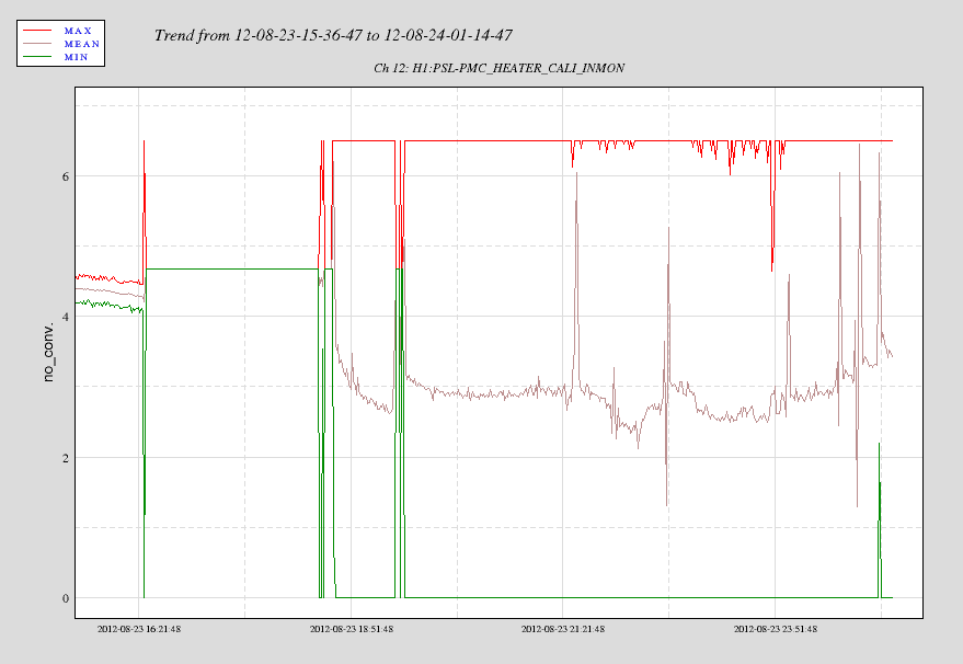
The PMC heater does not look healthy, and has been going between rails since the transition. I'm not sure what is causing this, but I think it'd be worse to leave the PMC with the heater off so I'm leaving it in this state overnight.

Images attached to this comment
H2 AOS
eleanor.king@LIGO.ORG - posted 14:49, Thursday 23 August 2012 - last comment - 17:33, Thursday 23 August 2012(3958)
Ring Heater turned on for cavity scan

(Jax, Elli)  At 13:59:25 local time (20:59:25 UTC) 630mA was requested from each segement of the ITM. Cavity scans are being recorded.  We'll turn the ITM ring heater off after 3 hours.

Running the ring heater is affecting the alignment of the cavity a lot, I'm having to increase the pitch offset on the ITM by about 25 counts every 2 minutes.  Wavefront sensors are on.

Comments related to this report
eleanor.king@LIGO.ORG - 17:33, Thursday 23 August 2012 (3969)

Ring heater has been swtiched off at 17:31.

H1 SEI
hugo.paris@LIGO.ORG - posted 18:11, Wednesday 22 August 2012 - last comment - 10:23, Wednesday 29 August 2012(3948)
HAM2-ISI - Testing progress

Electronics were troubleshooted.

SEI and SUS models were arranged to allow un-tripping HAM2-ISI Payload Watchdogs.

HAM2 model was re-compiled, installed and re-started after that. It is now running.

Matrices were filled

Input and output filters are loaded

The latest version (Version_2) of the unit-specific control scripts were copied from LASTI. They were made ready for use on HAM2. 

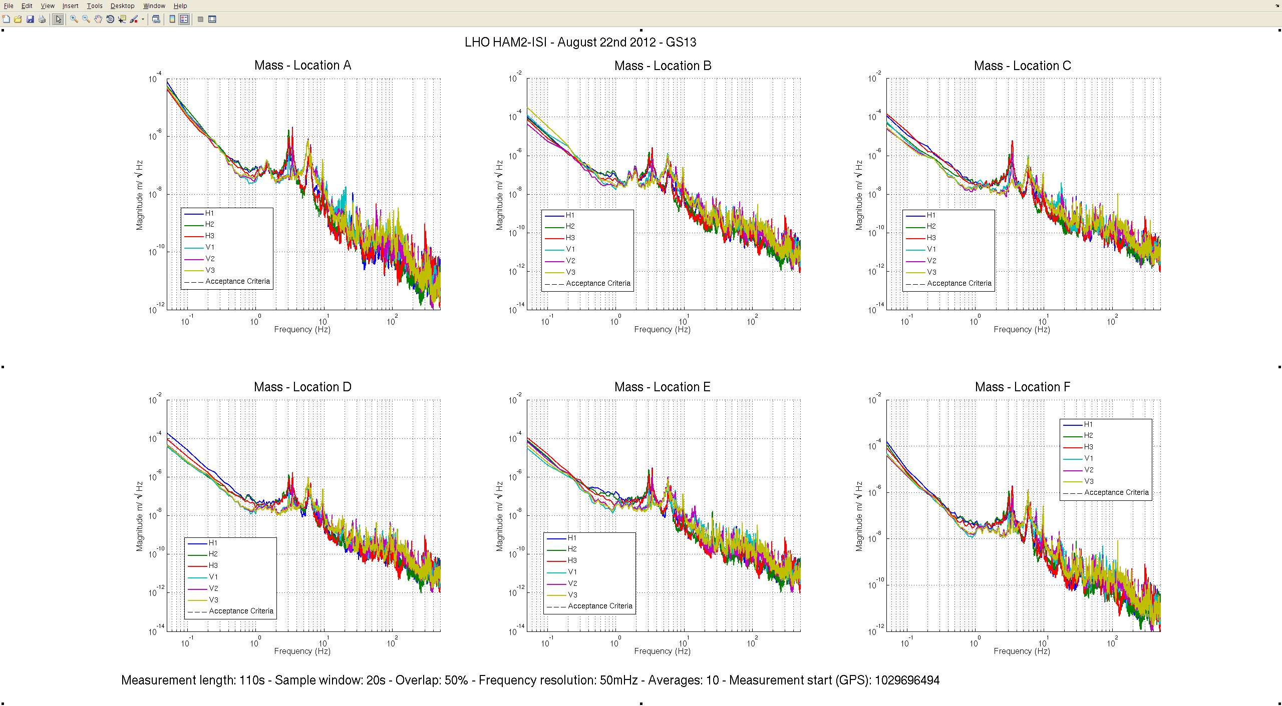
Spectra were taken on the ISI tilted. It is the worse configuration for GS13s and they all appear to be working fine (see attached plot).

Transfer function measurements are running overnight.

Images attached to this report
Comments related to this report
hugo.paris@LIGO.ORG - 16:45, Thursday 23 August 2012 (3965)

The transfer functions measured last night had features that are typical to mis-connected sensors/actuators. Deeper analysis allowed narrowing it down the the GS13s. 

We made a program to check for "cross-coupling transfer functions" (e.g. drive on H1, response on H2). It revealed that:

H1-GS13 was read on the channel of H3-GS13 
H2-GS13 was read on the channel of H1-GS13
H3-GS13 was read on the channel of H2-GS13
V1-GS13 was read on the channel of V3-GS13 
V2-GS13 was read on the channel of V1-GS13
V3-GS13 was read on the channel of V2-GS13

We checked our model and did not find a cause for such behaviour there. We moved on the the electronics rack and spotted the issue: GS13 In-field cables were connected to the wrong inputs on HAM2 sensor interfaces.

We ran a quick TF measurement between 500mHz and 5Hz. It confirmed that the sensors were now all correctly connected. This quick measurement is also in good accordance with what we measured on HAM-ISIs in the past which is encourraging.

TF measurement are running overnight on HAM2. They will be over by 7am. 


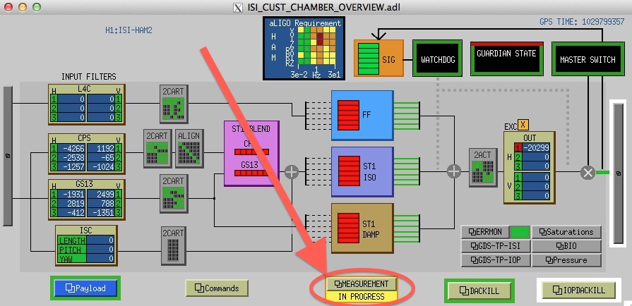
Note: A blinking notification was recently added to HAM-ISI overview MEDM screens (see attachement). It turns the green "measurement" button to blinking yellow when a TF is running. HAM2 overview screen can be seen on the Video6 monitor of the Control Room. 

Images attached to this comment
hugo.paris@LIGO.ORG - 10:23, Wednesday 29 August 2012 (4025)

Hugh and I added screwdriver tips under the top payload mass of HAM2-ISI last week, before the chamber was closed. They helped prevent this big mass of ~600lbs from causing unwanted resonances. Befoire/After comparison plots are attached.

We compared the latest transfer functions with the ones taken on LLO HAM2-ISI during the same phase of testing (Intitial In-Chamber Testing). Plots are attached. Accordance is good. We are confident that the unwanted resonance seen at 96Hz comes from the top mass. We plan on ajusting its boundary conditions with the optical table once the doors of HAM2 chamber are open again. 

Non-image files attached to this comment
Displaying reports 84721-84740 of 88593.Go to page Start 4233 4234 4235 4236 4237 4238 4239 4240 4241 End