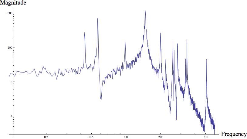
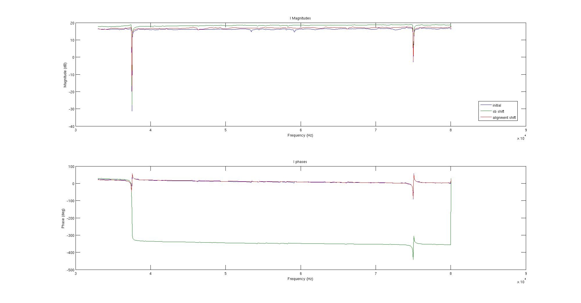
Tuesday the ISI table level was checked and found to be within 0.2mm, and on Wednesday we performed initial yaw measurements (yaw measured at 2.61 mrad).
Yesterday we measured the ITM yaw and horizontal position. The yaw was confirmed to be 2.6 mrad out of alignment (initial measurement done Wednesday) but the horizontal position was found to be 0.46mm from center, which is well within the ±1mm spec.
As Betsy stated in her alog we were able to correct the ITM yaw to ~400 µrad (the spec for rough yaw alignment is ±1mrad). After this we used the Microscribe to measure the gap between the corner cube retroreflector (used for y-axis distance measurement) and the ITM so we could get an accurate meaurement of the y-axis (longitudinal) position of the ITM. This gap was measured at 52.6mm and the total station measured 6982mm to the corner cube, resulting in a total distance from the total station to the ITM of 7034.6mm; the desired distance in 7041.3mm, so this shows the ITM structure to be to far forward on the ISI by 6.7mm. We are currently looking for the source of this error. Since the structure was moved in yaw, we also need to recheck the horizontal position of the ITM to ensure it is still within spec; these 3 degrees of freedom (yaw, horizontal position, and longitudinal position) need to be checked every time the structure is moved.
We are currently looking for the source of the FM longitudinal error as well.
Today, Jeff and Andres put the ETMy lower structure into the test stand clean room, and separated the chains, in prep for it's remodel for the monolithic. They unloaded the Dummy TM, Dummy PUM and wire segments and parked it in the adjascent fiber welding clean room. The ring heater crew will commence their addition to this structure tomorrow. I anticipate loading it with glass early next week.
This morning, IAS reverified that we needed to yaw the ITMy tower a few mRAD. We clamped both chains and took a baseline reading of the ITMy pointing in the clamped state. We then loosened the dog clamps holding the structure to the ISI table and took another reading. The dog clamps were still somewhat tight on the tower, no gap between the structure and table was noticeable. Jason will post the numbers in a subsequent entry. Using the new Pushers/Movers we were able to push opposite corners of the structure to reduce the yaw to ~20uRAD. We then tighted some of the dog clamps and observed that the yaw had walked out to ~400uRAD. We paused there and took the Y-axis reading. Unfortunately the structure appears to be out of position on the table in this direction by ~6mm. The initial placement of the structure nor the error in how the mass is suspended inside the structure account for this large misplacement. Dennis and Doug used the microscribe to measure the distance between the corner cube and the ITMy and also started looking into the optomechanical model in hopes to pinpoint where this 6mm error comes from. Meanwhile, they were going to continue with the foray of IAS measurements on the FMy. Fleshing out the next few days of interwoven IAS, Testing, and cartridge prep activities, but things look tight. We could not figure out a more efficient plan than the following: 1) determine how far ITMy and FMy structures need to be pushed around on ISI table (this afternoon-tomorrow morning) 2) push structures in x,y as needed, adjusting yaw as needed (tomorrow) 3) attach sleeve, vibrationabsorber payloads, continue fine IAS alignment to finalise yaw and pitch (Sunday) 4) SEI rebalance table payload, but leave locked until COB (Monday morning) 5) IAS measure ITMy to CP gap, SUS to adjust if needed Monday afternoon) 6) unlock ISI for TESTING (Monday night) 7) TEST (Monday night? - few days) 8) during testing gaps, prep suses for cartridge install (Monday-Wed)
The same procedure for the H2 ITMY L1 Open Light voltages were recorded for the H2 ITMY L2 Open Light voltages. A 30-second average of the H2:SUS-ITMY_L2_OSEMINF_*_IN1_DQ channels with thetdsavgcommand-line tool was used to record their values. Their values were halved, multiplied by (-1), and entered into the H2:SUS-ITMY_L2_OSEMINF_*_OFFSET channels. The gains for these channels were calculated by normalizing the open light counts to 30,000cts.Open Light (cts) UL = 27204.7 LL = 17354.3 UR = 19496.5 LR = 20515.5 Offsets [-(open light)/2] (cts) UL = -13602 LL = -8677 UR = -9748 LR = -10258 Gains [30000 / (open light)] UL = 1.103 LL = 1.729 UR = 1.539 LR = 1.462 Open Light counts after normalization [tdsavg] (should be ~15000) UL = 14998.4 LL = 14997 UR = 14999.8 LR = 14993.3
The H2 ITMY L1 Open Light voltages were recorded with a 30-second average of the H2:SUS-ITMY_L1_OSEMINF_*_IN1_DQ channels with the OSEMs completely backed off of their flags. Their values were halved, multiplied by (-1), and entered into the H2:SUS-ITMY_L1_OSEMINF_*_OFFSET channels. The gains for these channels were calculated by normalizing the open light counts to 30,000cts.
controls@cdsws2:/ligo/svncommon/SusSVN/sus/trunk/QUAD/H2/ITMY/SAGR0/Data 0$ tdsavg 30 H2:SUS-ITMY_L1_OSEMINF_UL_IN1_DQ H2:SUS-ITMY_L1_OSEMINF_LL_IN1_DQ H2:SUS-ITMY_L1_OSEMINF_UR_IN1_DQ H2:SUS-ITMY_L1_OSEMINF_LR_IN1_DQ
27866.8
25170
29253.2
23004.8
Open Light (cts)
UL = 27866.8
LL = 25170
UR = 29253.2
LR = 23004.8
Offsets [(open light)/2] (cts)
UL = -13933
LL = -12585
UR = -14627
LR = -11502
Gains [30000 / (open light)]
UL = 1.077
LL = 1.192
UR = 1.026
LR = 1.304
Open Light cts after normalization (should be ~15000cts)
UL = 15006.8
LL = 15001.3
UR = 15007.3
LR = 14999.7
MichaelR, JanP, RickS Yesterday, we measured the drive level to the FSS EOM. Measuring directly with an oscilloscope with the input set at 50 ohms, we found the following: Measured drive voltage into FSS EOM at 21.5 MHz 2.12 Vp-p 2.12/(2*sqrt(2)) = 750 mVrms 1 dBm = 1 mw into 50 ohms P=V^2/R; V in rms .75^2/50 = 0.0112 W -> 10.5 dBm New Focus web site states 0.1-0.3 rad/V for Model 4003 modulators 2.12 Vp-p -> 1.06 Vp -> 0.106 - 0.318 modulation index, Gamma Thus the ratio of the power in the first order sideband to that of the carrier will be between 0.0028 to 0.0259, i. e. the first order sidebands should be a factor of 355 to 39 times lower than the carrier. We will measure the sideband-to-carrier ratio with the reference cavity soon.
Sadecki, Bland This morning, the 4 UIM and 4 PUM OSEMs were aligned and set to 50% OLV. This took both of us, due to the inability to see the centering of all of the OSEMs with the FMy 6 inches away from the ITMy structure. In the afternoon, Dennis, Doug, and Jason started IAS measurements of the ITMy relative to the ISI. They determined that the ITMy is in-fact over 2mRad out of spec in yaw. Documentation suggests that we should yaw the structure to reduce the error to ~1mRad before using the top stage yaw adjustment inside the suspension. So, we pulled out and started building the QUAD pusher/mover assemblies to use tomorrow morning.
Attached are plots of dust counts > .5 microns.
Andres R. and Jeff B. installed the Quad-4 Upper Structure on the BSC-6 ISI at End-Y. No issues or difficulties were encountered, although the fit under the test stand is very tight. The Lower Structure is at the end station and is ready for conversion to glass.
Noticed CP6's dewar was exhausting through the "Full Trycock" circuit and that the nominal pressure regulated exhaust circuit was warm and that the tank vapor pressure was 0 psi indicated (~15 psi is nominal). This was likely in this state by the driver following the most recent delivery -> I closed the Full Trycock valve. Tank vapor pressure should build up to normal in the next day or so.
MichaelR, JanP, RickS Yesterday, we continued the work on the FSS path alignment. We found that the EOM mounting base did not allow it to get to the 10 cm beam height so we replaced it with a modified iLIGO base. Here are the powers we measured: power at input to the FSS power adjust PBSC 400 mW power downstream of PBSC 20 mW power at base of FSS periscope 8.5 mW visibility (measured with drive to EOM disconnected) (160-60)/160 = 63%
Attached is a DTT whitenoise measurement of the ITMY R0 Pitch DoF with a reference from 11/23/2011. Today's measurement is in red and with a 0.01Hz resolution. Measurements were performed after today's mechanical adjustments.
Note that this data was taken the in the interim because mechanical adjustments to the reaction chain. Newer over night data (full aLOG coming shortly) shows much less badness. However, the lessons learned from this transfer function: - Because only the higher resonant frequencies have changed, whatever mechanical problem that is causing the badness is likely *internal* to the suspended chain. - The most likely culprit: either cabling jumps between the stages are extra stiff for some reason (temporarily having it moved, cocked to one side, etc etc), or there was rubbing between chains of the the newly aligned lower stage flags. - It's not shown here, but the main chain was taken at the same time, and didn't show any particular badness, so all fingers point to the cabling. Moral of the story -- things (on the reaction chain) look better in future measurement, with very little mechanically changed.
Travis S., Betsy B., Jeff G. Today,more mechanical adjustments on the H2 ITMY QUAD were made today. The diagonalization measurements were run on the M0 and R0 top masses for the Vertical and Yaw degrees of freedom. Results attached. M0 Vertical isolation = ~18dB M0 Yaw isolation = ~17dB R0 Vertical isolation = ~7dB R0 Yaw isolation = ~11dB
Dave B., Richard M., Filiberto C., Jeff G. The SUS H2 ITMY Simulink modelh2susitmy.mdlwas modified today to accommodate the L2 (UIM) AOSEM signals. On theh2susb478machine, the first ADC card's "cardNum" is designated 0 (zero) in the Simulink model; the second ADC "cardNum" is 1 (one). The previous version of theh2susitmymodel routed the ITMY PUM signals to the first ADC card on theh2susb478machine. According to the latest BS, ITM, and FM Suspensions Controls Wiring (D1001725-v9), the PUM controls wiring should be routed to the second ADC card ("cardNum" = 1) on theh2susb478machine. The appropriate changes were made toh2susitmy.mdlto reroute the PUM signals to "cardNum=2". The new version was compiled and make installed ontoh2susb478. The signals were confirmed on the H2 ITMY PUM by medm readout. The AOSEMs now can to be normalized and centered to the flags.
Attached are plots of dust counts > .5 microns.
Today, Travis moved 62g from the AR side of the UIM to the HR (which was already the heavy side of the mass) in order to free up more range on the pitch roll bar adjusters. This did the trick and brought the pitch in to ~100uRAD. We then moved on to aligning the UIM and PUM OSEM/flag pairs. This was immediately problematic in that the signals of these 8 OSEMs looked strange. Richard help us diagnose that the L1 (UIM) signals were connected to the L2 (PUM) MEDM and vice versa. This was remedied via switching the 25pin 225 cable connections at the feedthru panel. Unfortunately, there were more troubles with L2. Dave discovered a DUO tone channel in the wrong place, and Garcia had some residual code changes to make. This recovered 3 of the 4 L2 channels, but there was still one that looked fishy. Garcia is investigating it more tonight. I am crossing my fingers that it is not the quadra-puss cable on the QUAD. I was able to align and set the 2 lower BOSEMs of the UIM to 50% OLV, but was running out of range on the uppers when the LVEA went laser safe and I quit for the night. More alignment ...to be continued.
Yesterday, seismic restarted testing HAM-ISI in the staging building. It seems that one of the horizontal GS13 is malfunctioning. The symptoms are similar to those we see when the proof mass is stuck (no low frequency response but high frequency response looks OK). After hitting the GS13 with a wrench and handling it, the mass is still stuck. I have attached Powerspectra of the 3 horizontal geophones when the ISI is locked (H3 geophone is the bad one).
The horizontal GS-13 POD SN 68 was opened and inspected. The flexure rods were not broken and the proof mass was moving freely when the geophone was leveled. One kinematic foot or the crossbar was probably not tightened down allowing the geophone to tilt inside the leveled can. Consequently the mass proof was touching the stops.
Kinematic feet of the horizontal GS13POD SN 68 were readjusted and the crossbar tightened up. After adding the can and reinstalling the GS13 in the HAM-ISI, a powerspectrum (attachment) confirmed that the geophone is functioning properly.
Today we moved the ETM Quad-04 to the Y end station. The Lower Structure weighed 539lbs and the Upper Structure weighed 255lbs. Total weight for the metal build of Quad-4 is 794lbs, which should be close to its’ final weight. The next step is to mount the Upper Structure to BSC-6 and prep the Lower Structure for the monolithic build.