Displaying reports 85961-85980 of 88300.Go to page Start 4295 4296 4297 4298 4299 4300 4301 4302 4303 End
Reports until 23:01, Monday 12 March 2012
H2 ISC
rich.abbott@LIGO.ORG - posted 23:01, Monday 12 March 2012 (2418)
H2 TMS Cable Damage Analysis
Performed a visual and electrical analysis of a failed cable used in the Transmon ISC cabling.

Cable serial number S1104079
Part number D1000223-v1, 216 inches

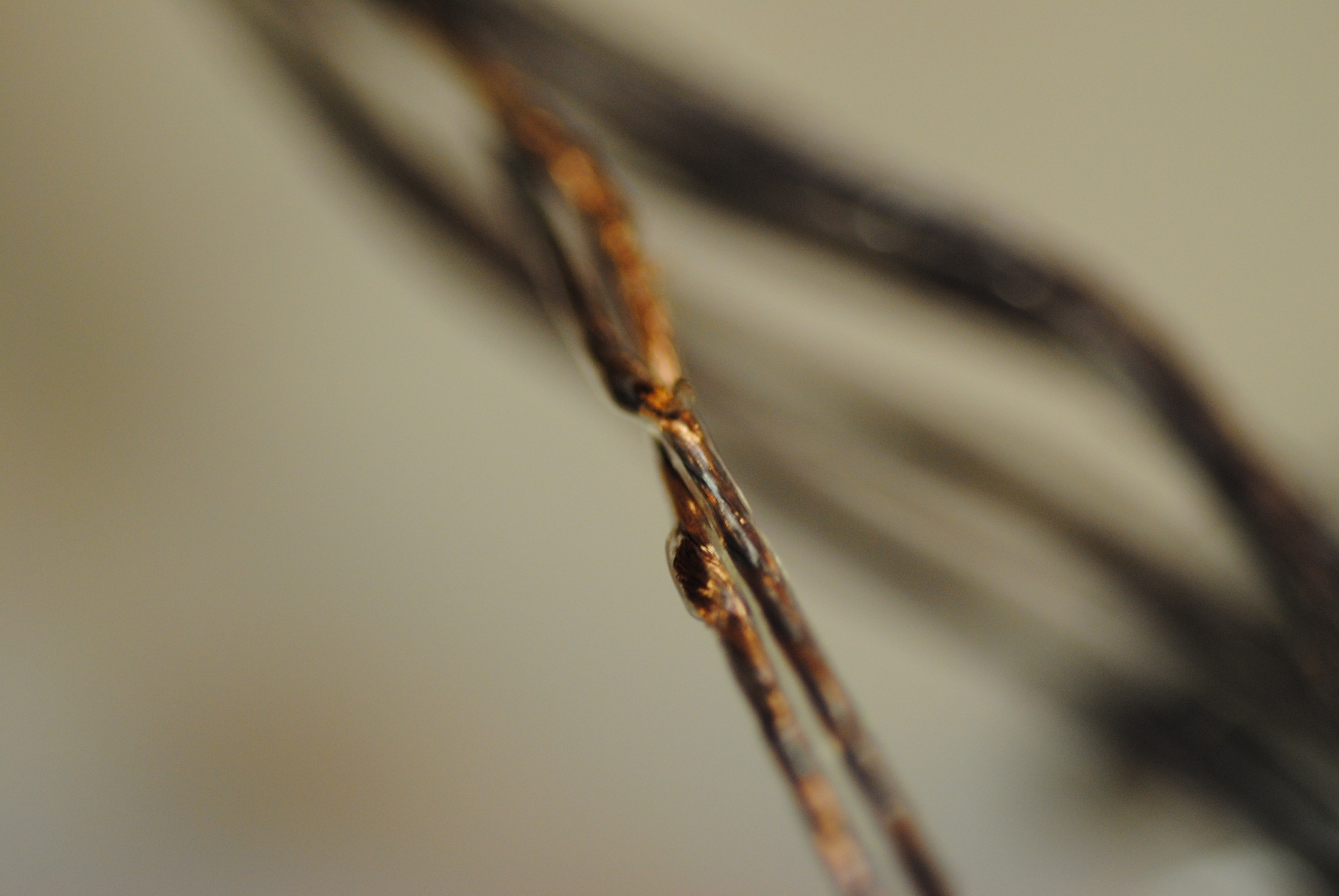
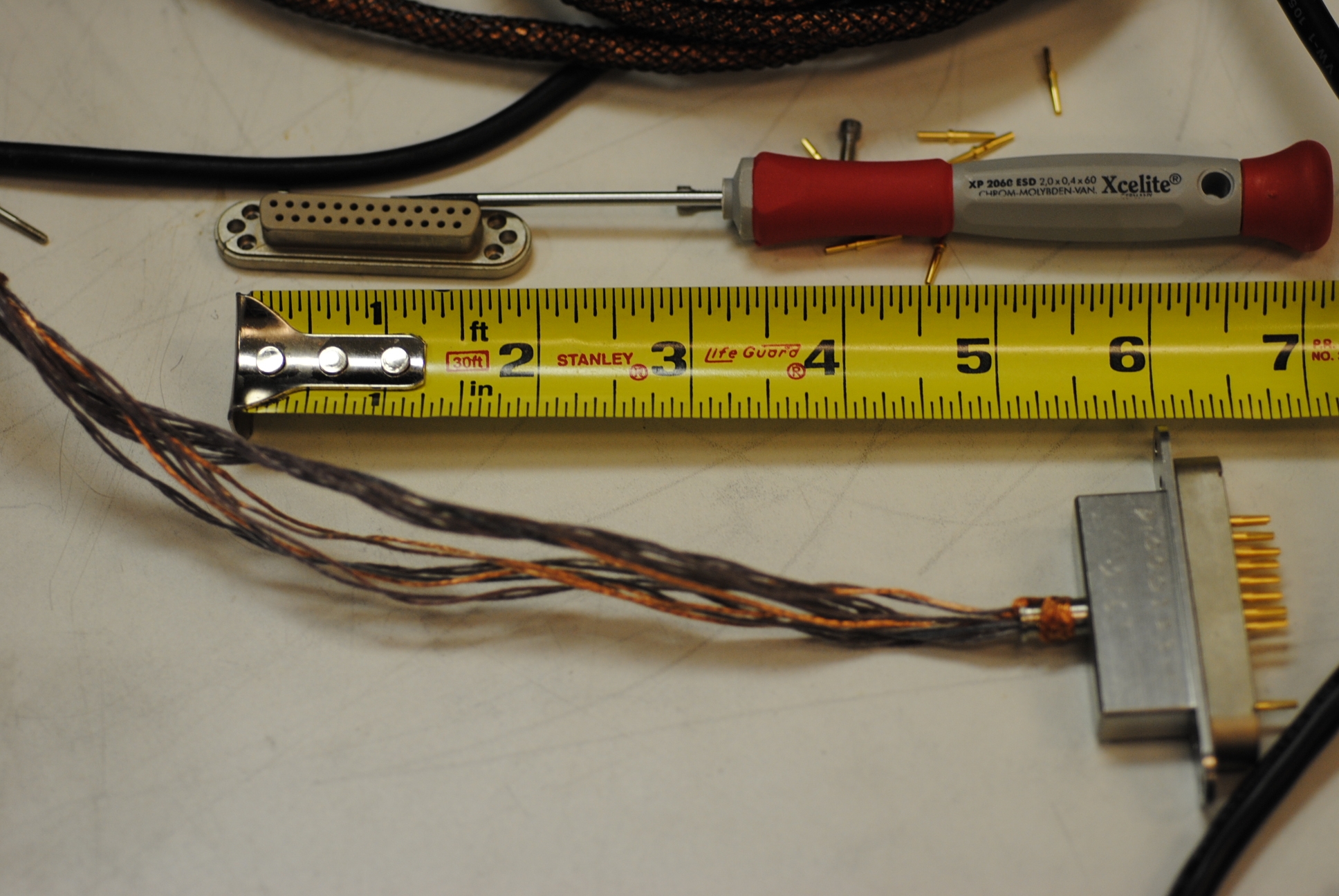
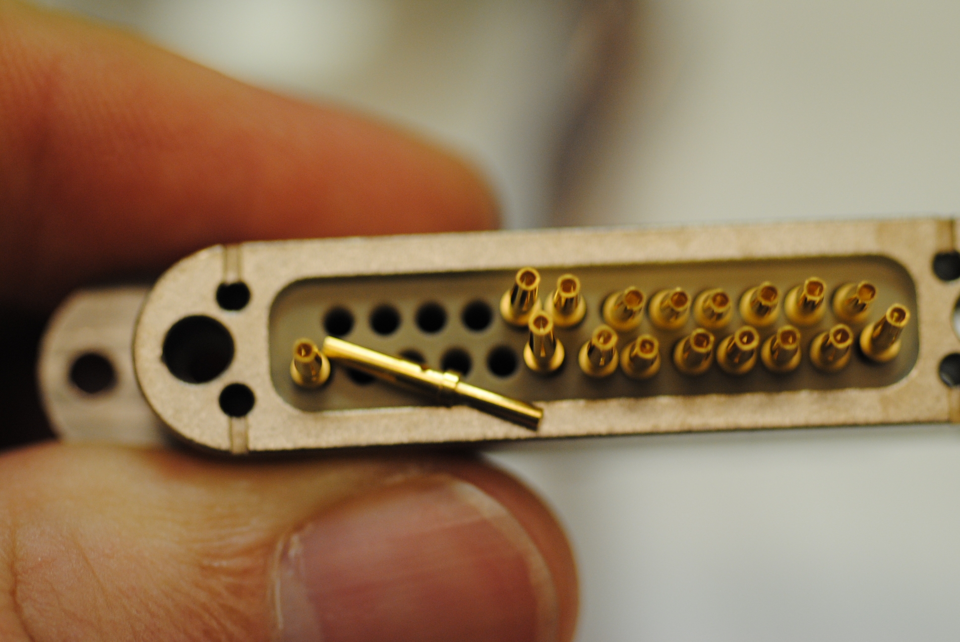
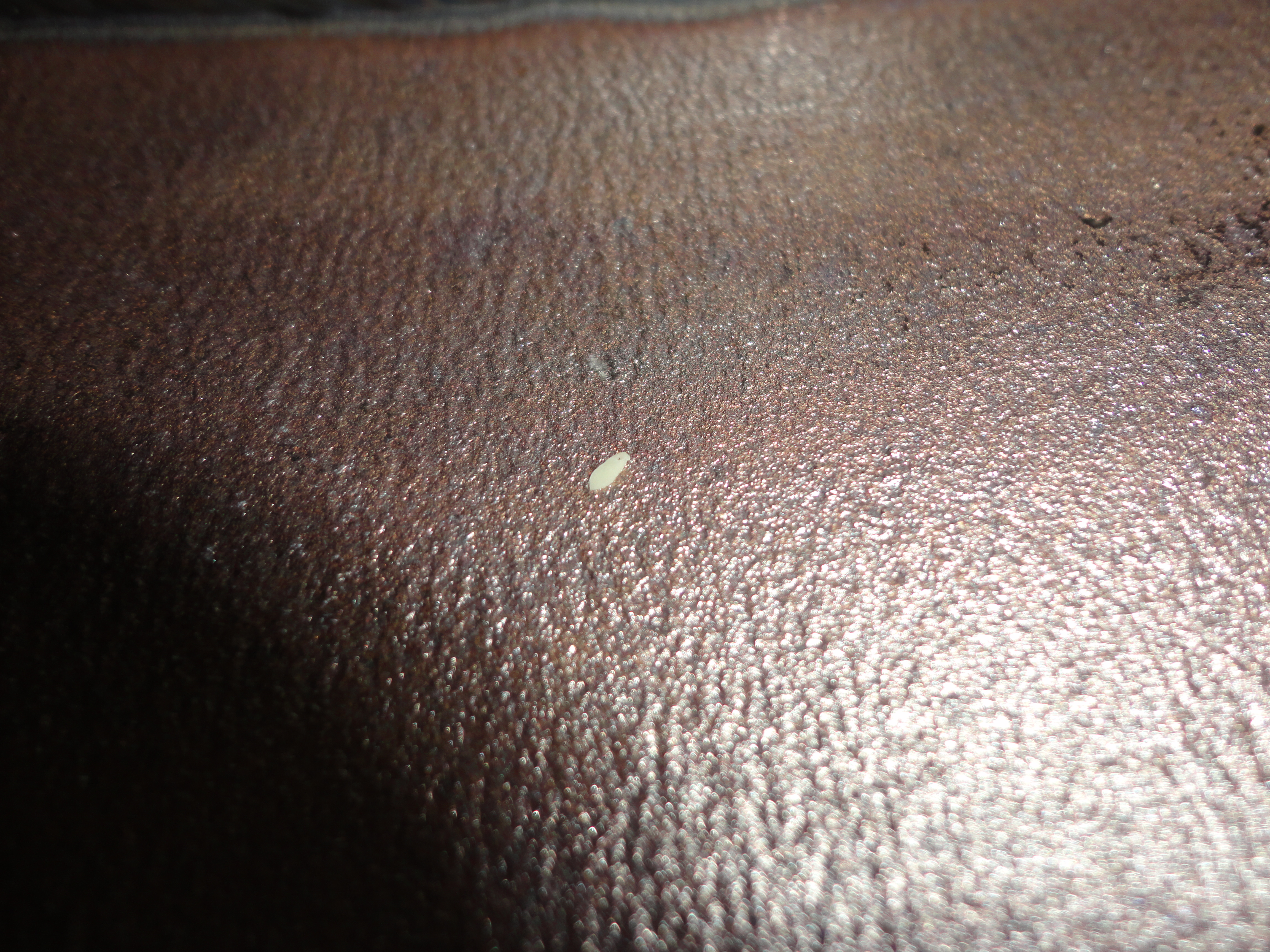
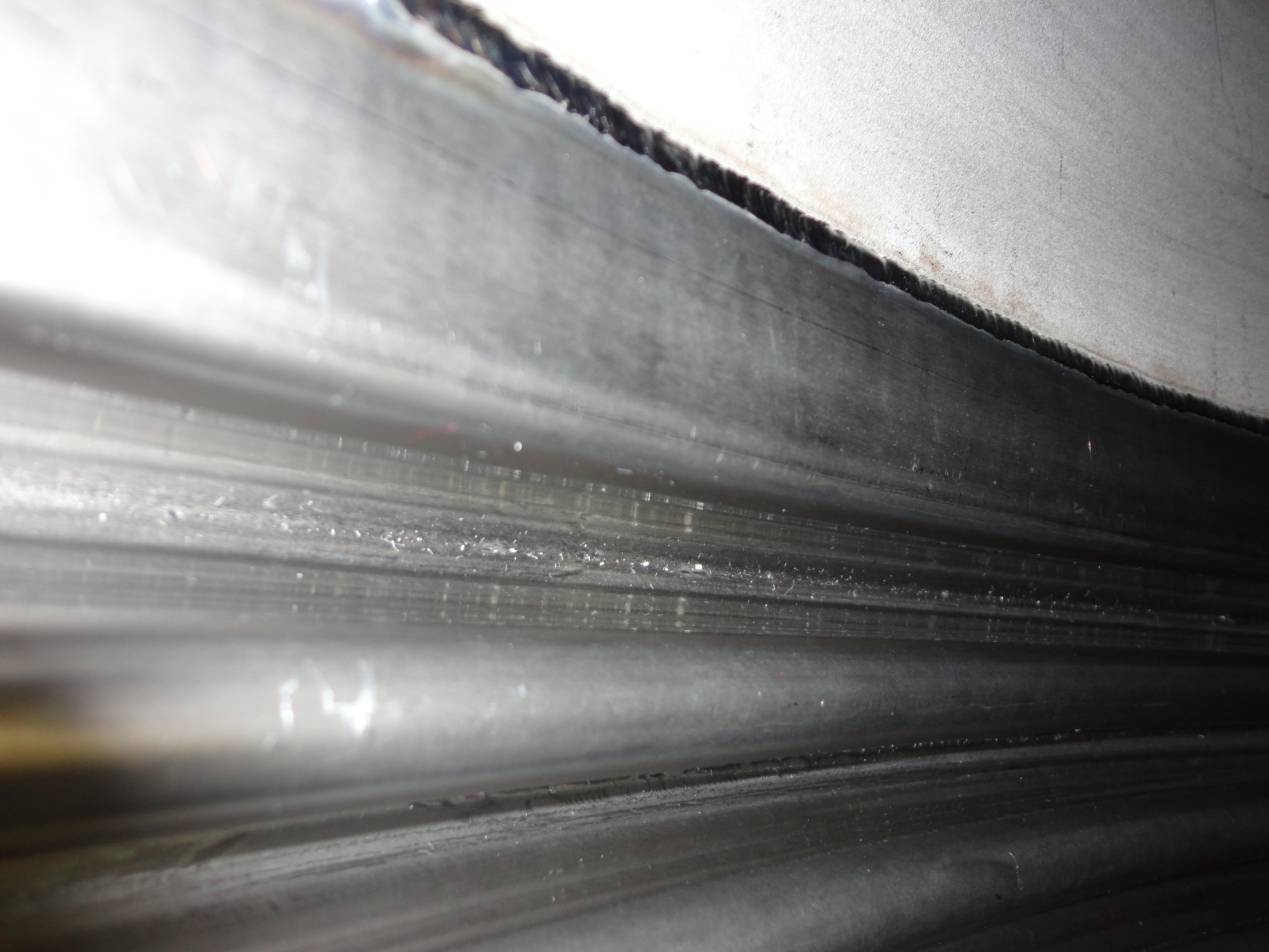
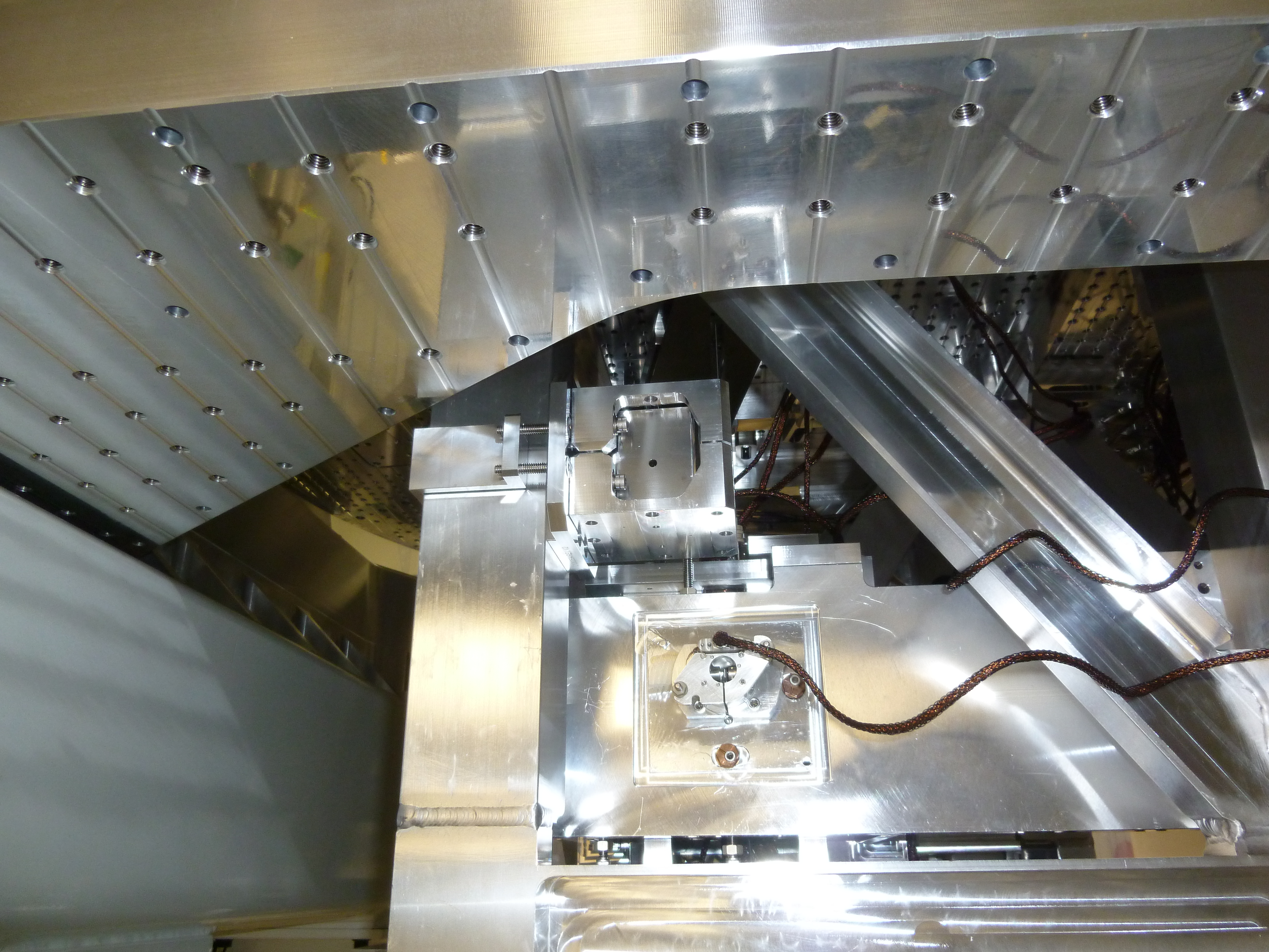
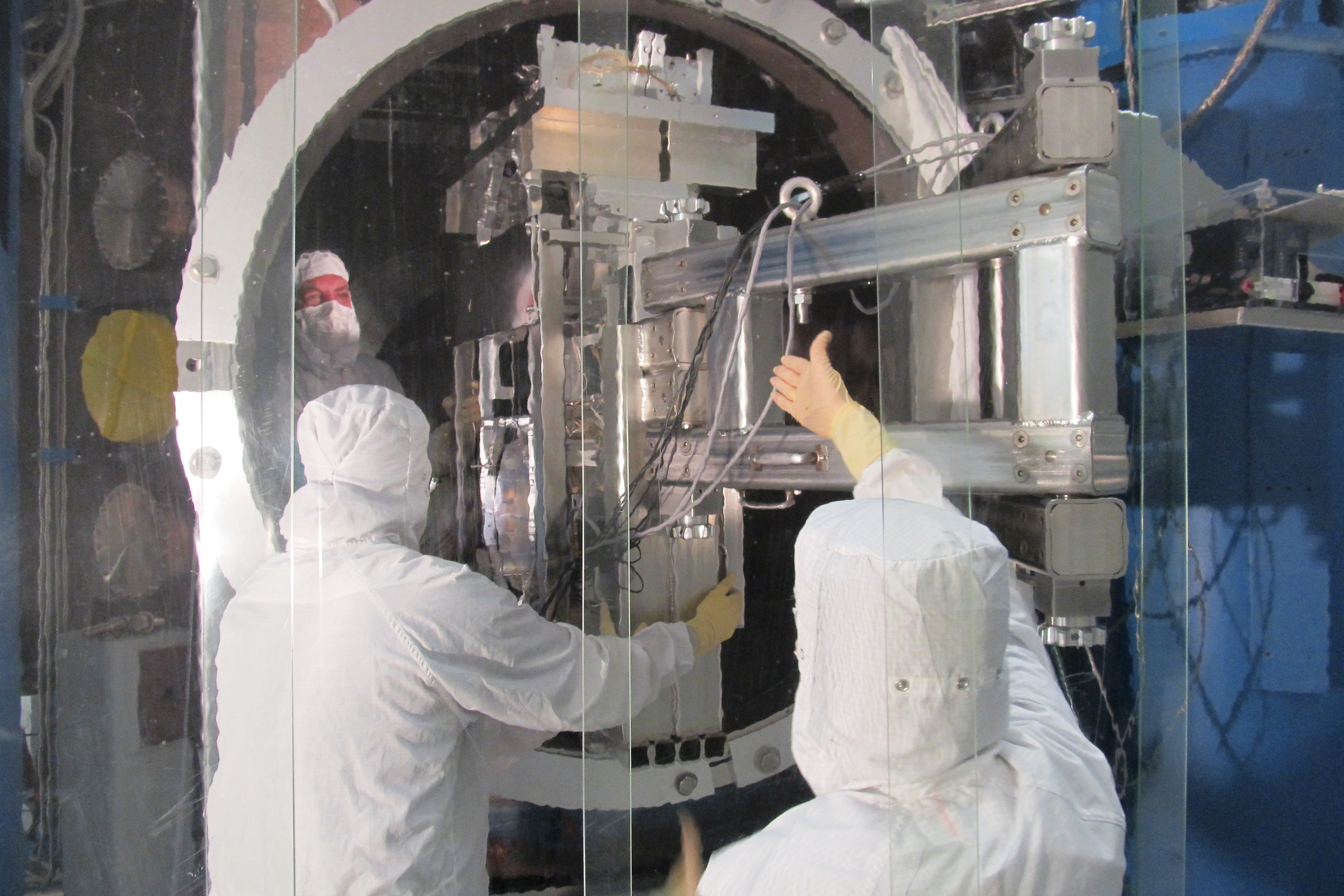
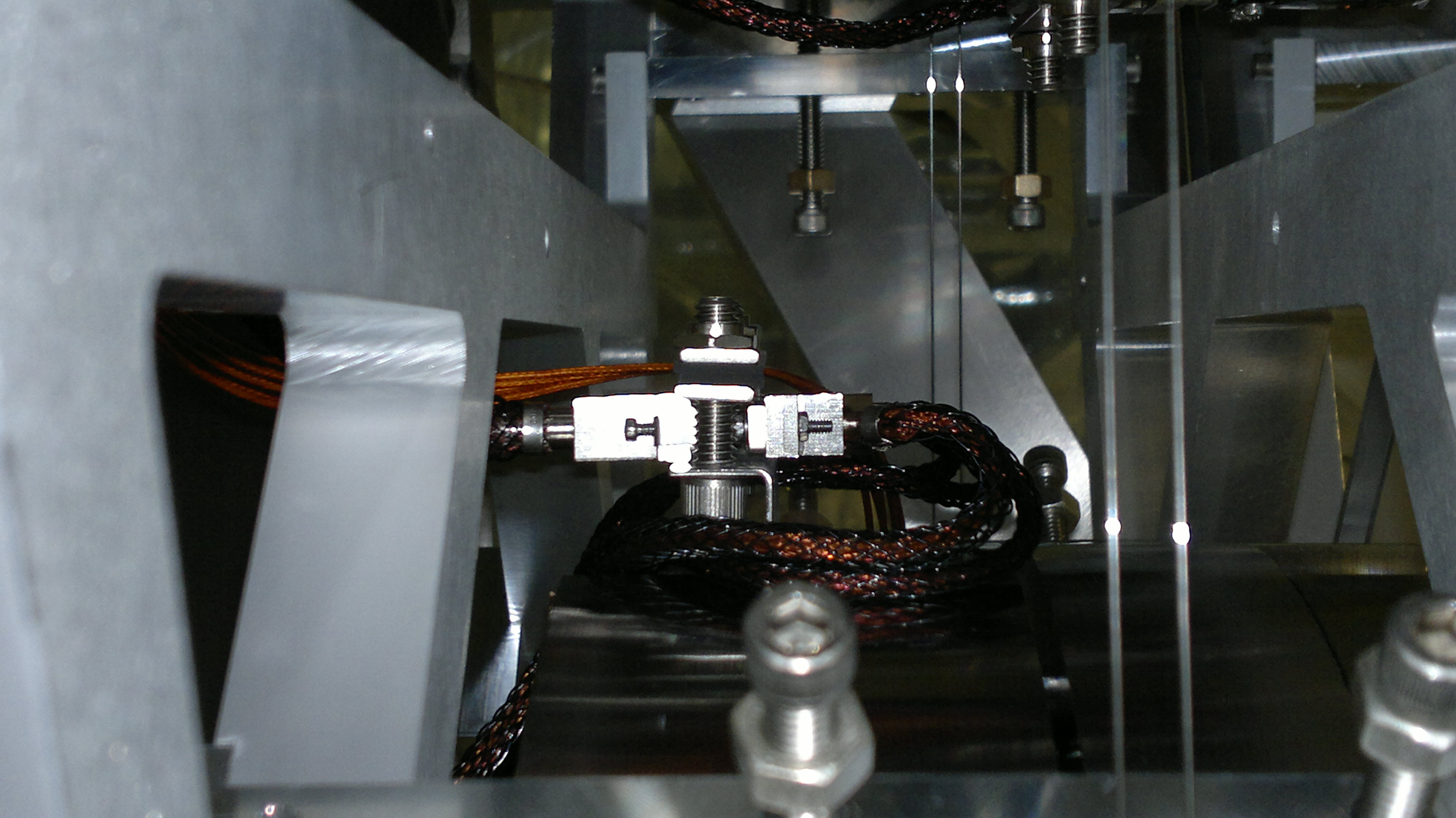
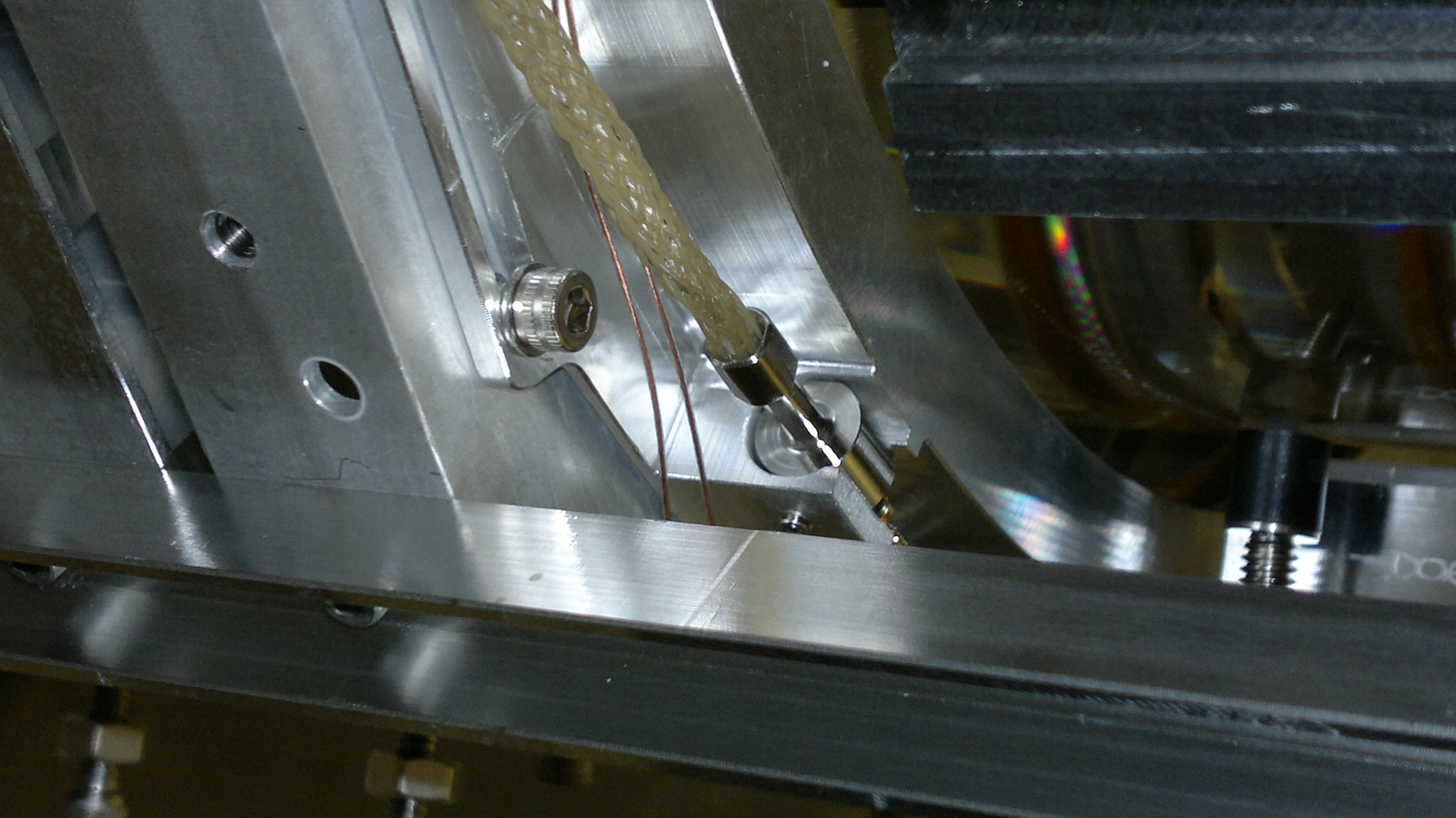
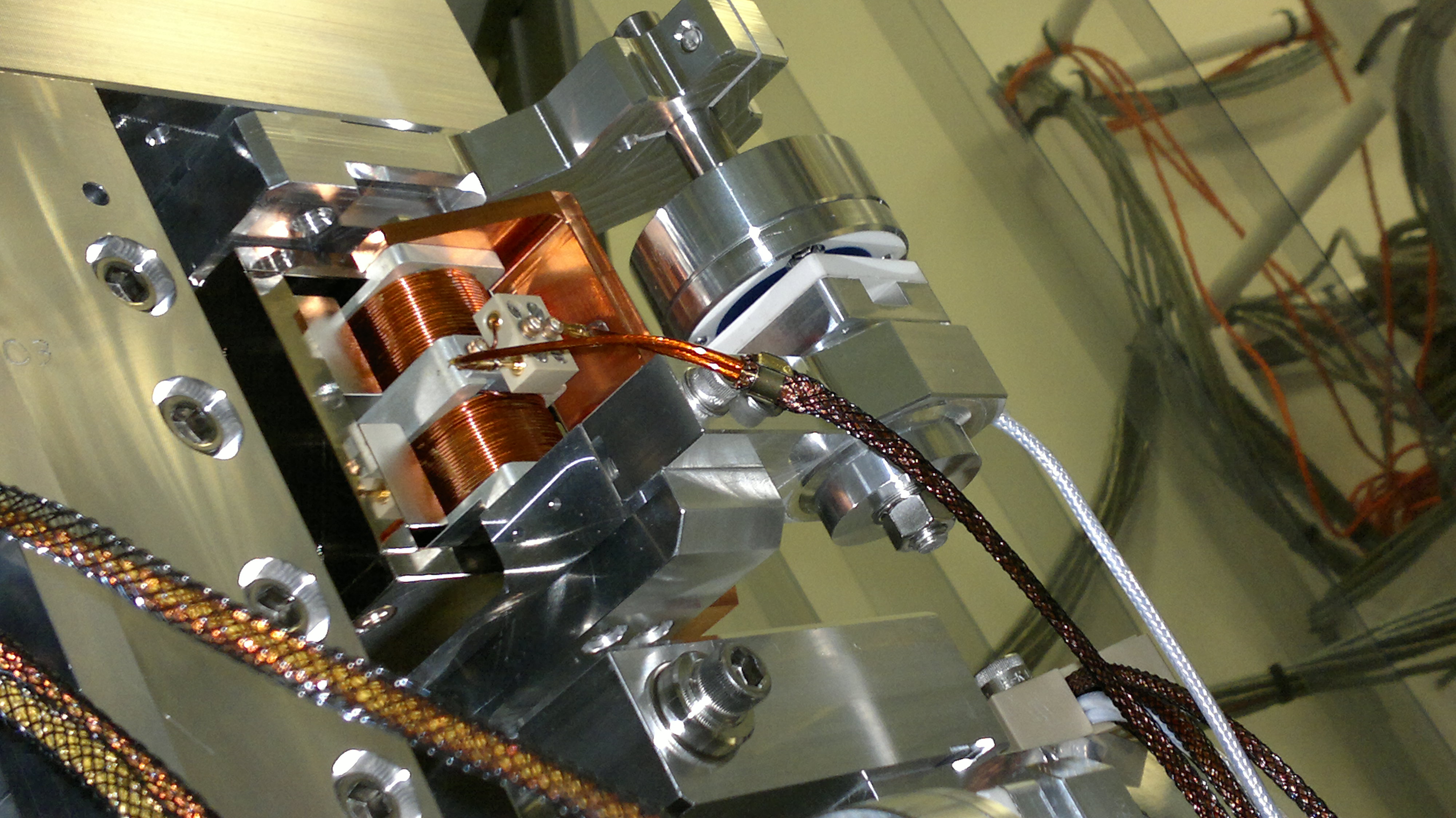
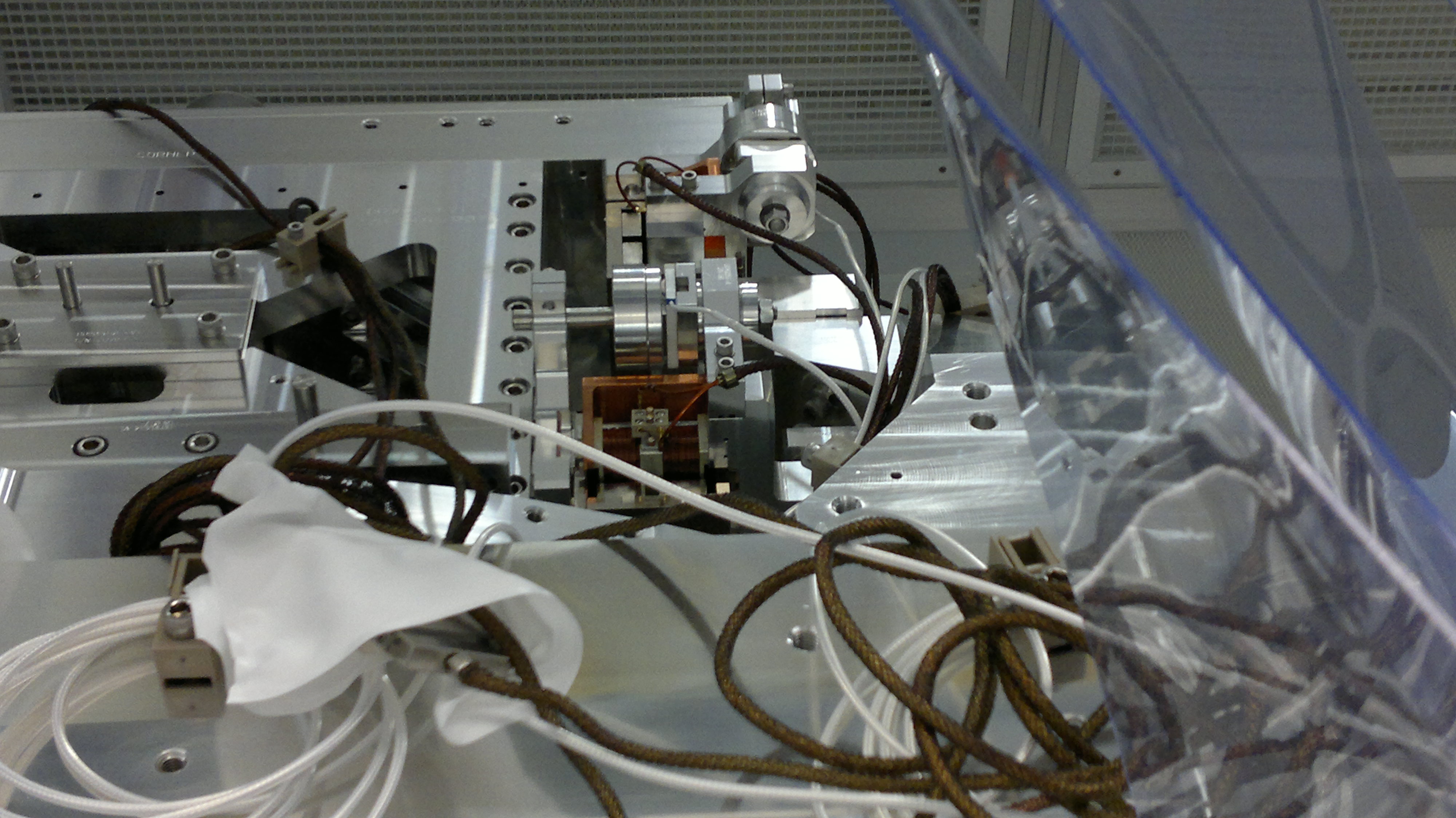
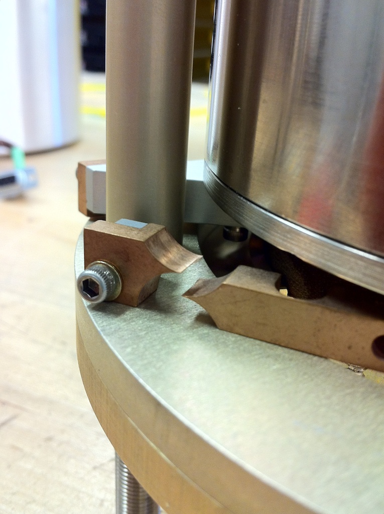
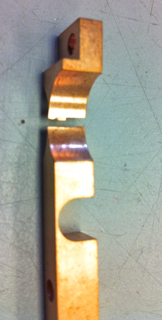
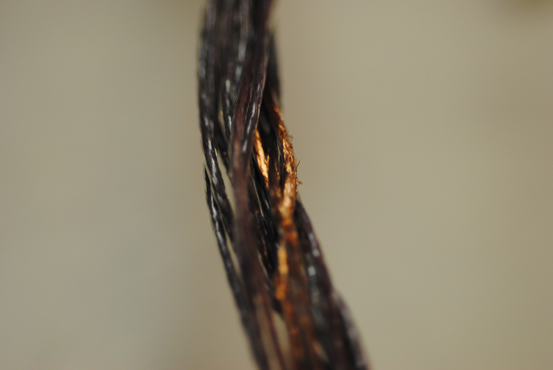
The cable exhibited multiple short circuits between individual conductors and between conductors and the cable shield.  Took the cable apart and found that some of the conductors had abrasion damage that resulted in failure of the dielectric.  Other conductors showed pressure induced cold flow of the Teflon dielectric.  Also, along with substantiating evidence of this damage, it is clear that each pin is not well sized and poorly constrained within the PEEK support of the connector body.  See the pictures for a better understanding.

File 380 shows abrasion damage
File 383 shows pressure induced cold flow of Teflon
File 386 gives perspective as to where the damage physically occurred
File 385 shows how the pin diameter compares to the hole diameter (aids in understanding mating problems)
Images attached to this report
LHO General
patrick.thomas@LIGO.ORG - posted 18:59, Monday 12 March 2012 (2417)
plots of dust counts
Attached are plots of dust counts > .5 microns.
Non-image files attached to this report
H2 SYS
rich.abbott@LIGO.ORG - posted 18:29, Monday 12 March 2012 (2416)
ITMY Cable Grounding and Shielding Check
Dan, Vincent, and I measured the particulars of the SUS, SEI, and ISI cable shields feeding into BSC8.  In summary, there are two geophone cables that are showing anomalous grounds on the shields, but all other cables are fine.  The geophone cables are likely the same issue we saw in the end station, so Vincent and Jim are going to tighten the strain relief screws on the d-subs that serve the geophones, but this can't be done until tomorrow.  If this doesn't fix the problem, there will be some head scratching.
H2 SUS
jeffrey.garcia@LIGO.ORG - posted 16:59, Monday 12 March 2012 - last comment - 07:30, Tuesday 13 March 2012(2415)
H2 SUS FMY measurements begun
Measurements on the H2 SUS FMY in BSC8 were begun today at around 16:50 PST (23:50 UTC).
Comments related to this report
jeffrey.kissel@LIGO.ORG - 07:30, Tuesday 13 March 2012 (2419)
The transfer functions that Jeff G started last night, have completed, and they are stored and committed to the repo, under
${SusSVN}/sus/trunk/BSFM/H2/FMY/SAGM1/Data/2012-03-12_H2SUSFMY_M1_0p01to50Hz_all_DoFs.mat

Attached are the results, plotted using,
${SusSVN}/sus/trunk/BSFM/Common/MatlabTools/plotBSFM_matlabtfs.m

I found that, regrettably, either
- FMY is still rubbing; in fact, worse than before (See pg 2)
- The watchdog tripped throughout the entire measurement (or at least the low frequency end) (See pg 1, 5, 6)
- The coil driver whitening/BIO settings (which I'm not sure were checked to be set properly after Richard was finished playing) were not set properly for the "normal" drive for a transfer function -- this could be the cause of watchdog tripping / bad SNR
- The OSEMs are totally broken. (See pg 3)
- The mechanics of FMY are [damaged/poorly suspended/out of alignment].

I don't *what* the heck's going on with vertical, but I'm pretty sure the other DOFs (L, P, Y) are watchdog trips / no signal drive; T looks like rubbing. 

--------------

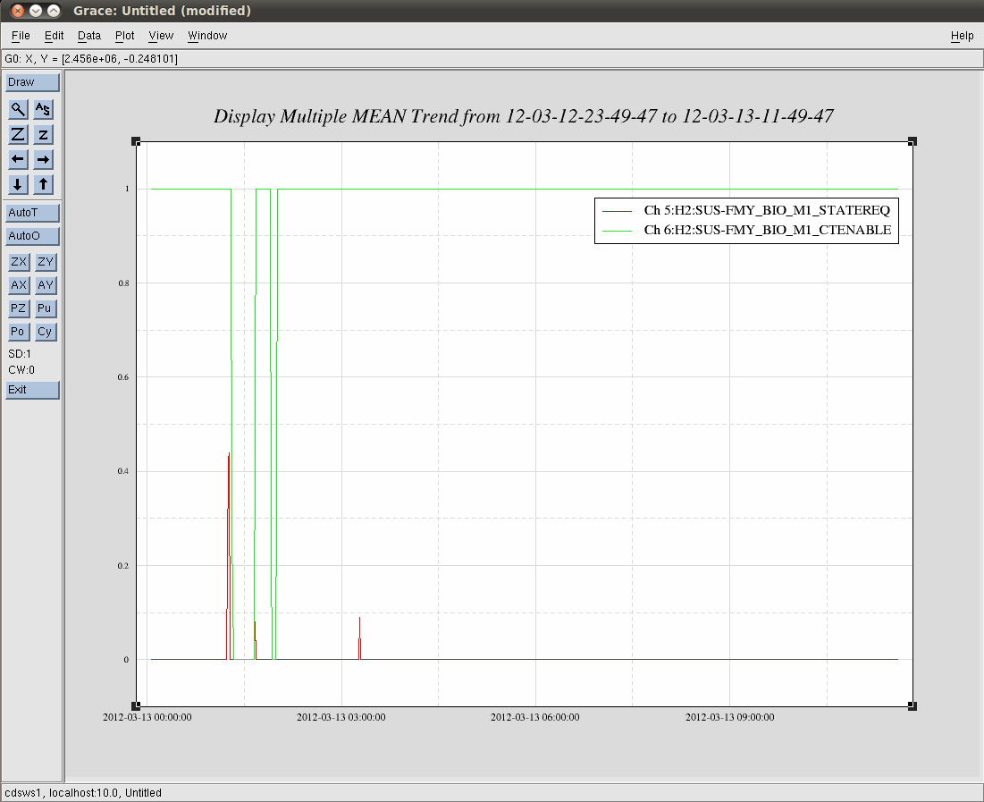
I've later confirmed that the H2:SUS-FMY_BIO_M1_STATEREQ state request channel was to 0 (see .png attachment) BBUUTT -- I'm not exactly sure if this disallows excitation, or puts the analog switches in a weird state. The digital compensation filters were turned on in the appropriate state...

--------------
Taking DTT TFs now...
Images attached to this comment
Non-image files attached to this comment
H2 FMP
jodi.fauver@LIGO.ORG - posted 16:40, Monday 12 March 2012 (2414)
BSC8 Clean up from Fiber Break
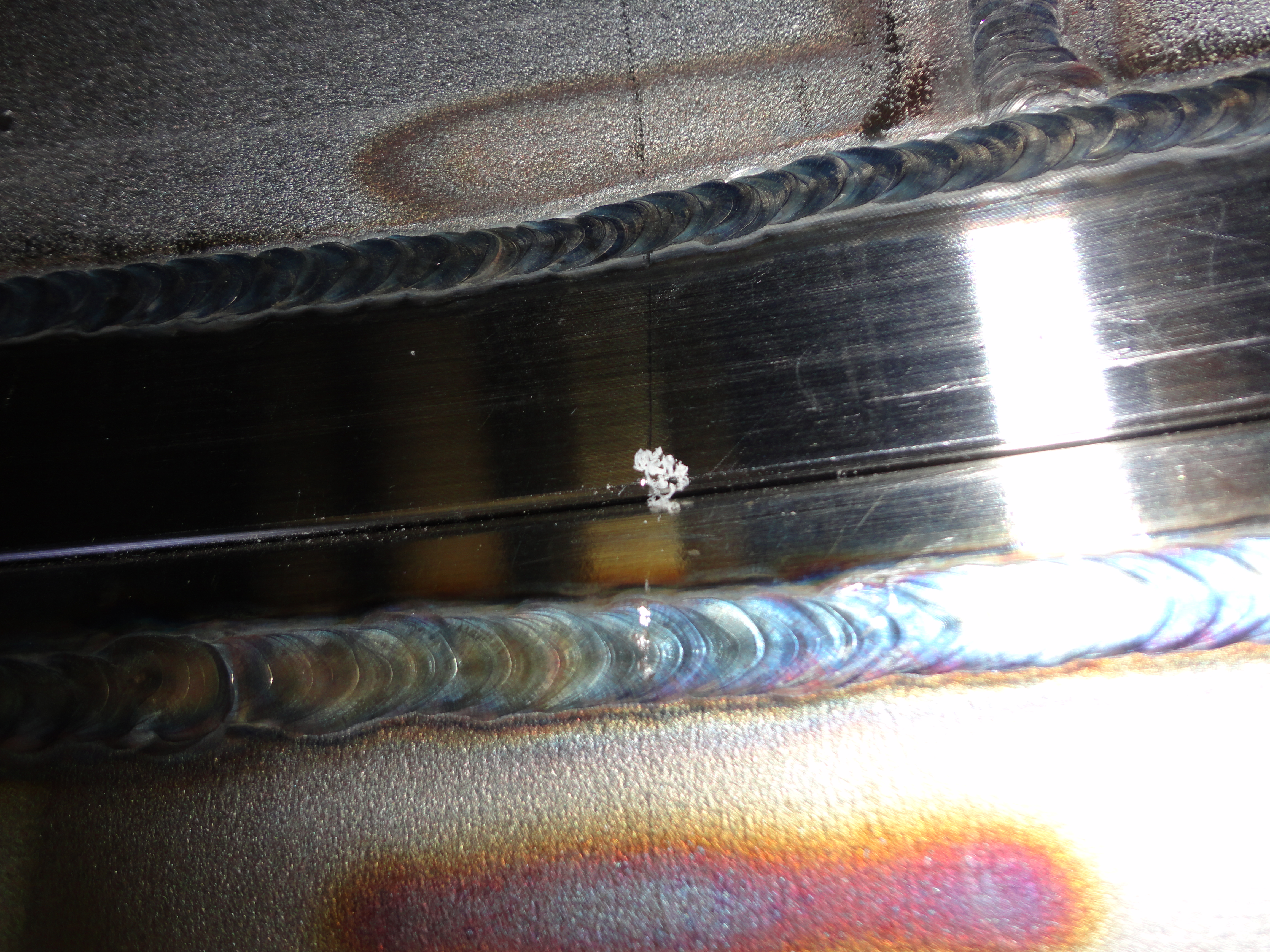
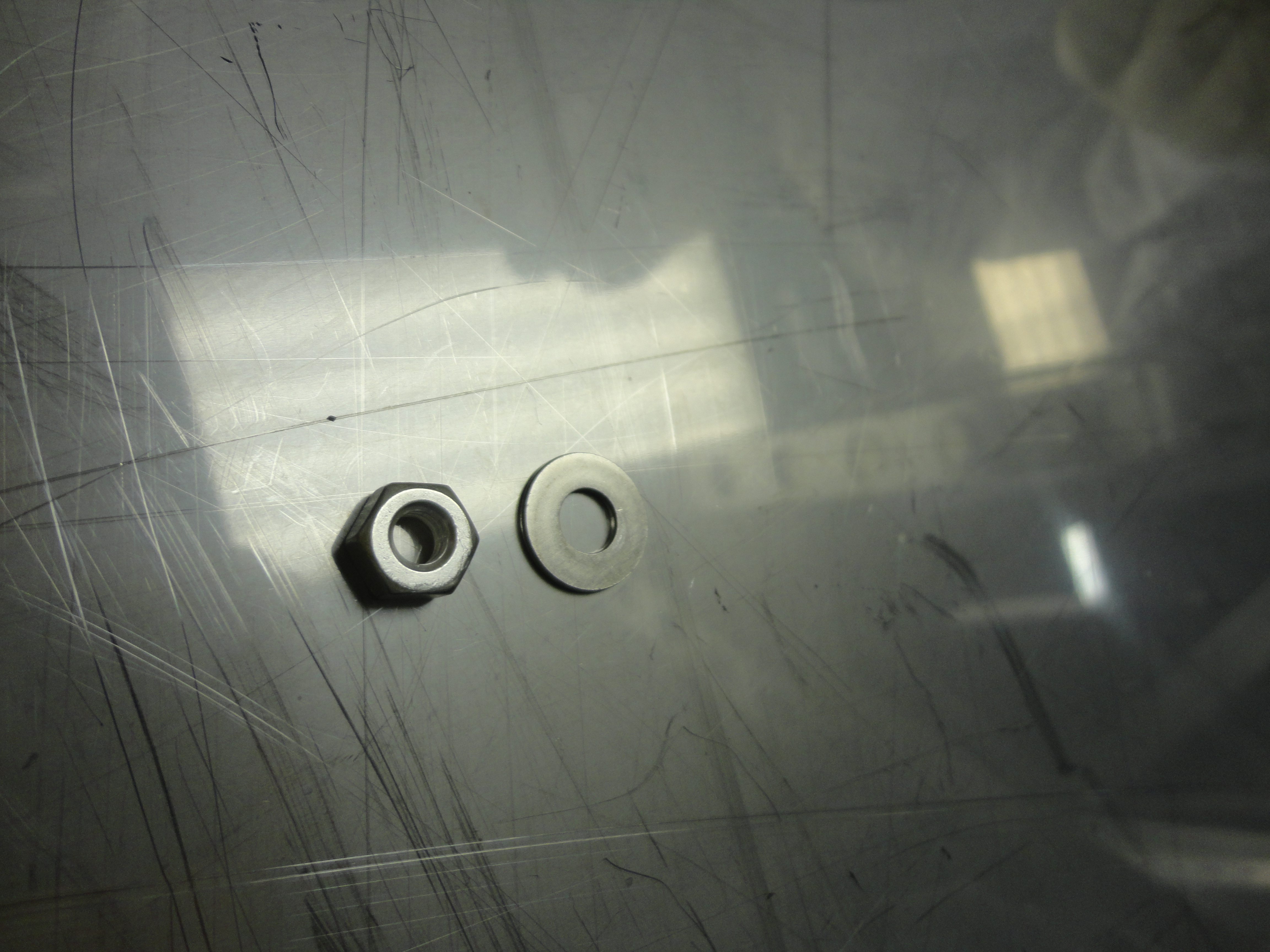
We made a checklist for serious clean-up and staged for an entry to BSC8. The repair arm, elevator and 5-axis table were covered with C-3 and swung out of the way (inside the cleanroom)so that we could get into the chamber. Travis removed the Quad lower sleeve and a pan of tools. Travis and I covered the remaining SUS structures and then documented the condition of the chamber, gate valve #3, ACB, Y-Beam manifold and various nozzles. Inspection showed debris (glass, metal, fabric fibers, human hair, ?Teflon, ?Viton, glove material) in the lower viewport nozzles and in all the beam tube bellows convolutions. (This is somewhat discouraging since these areas looked as bad as they did prior to in-chamber cleaning. Maybe we need to inspect and then vacuum our way out of the chamber starting at the furthest point where we find debris.A few pix attached.) In addition, we carefully inspected all uncovered flat surfaces including nozzle bottoms and ACB for left over tools, hardware, etc. On the upper shelf of the ACB, we found one free-range silver plated nut and one free-range stainless washer (By free-range, I mean unattached to any other hardware such as a bolt or screw. Pix attached). No hardware appeared to be missing from the ACB.

Mark L. and Chris will go in tomorrow morning and get the vacuuming and wipe down completed.
Images attached to this report
H2 SEI
vincent.lhuillier@LIGO.ORG - posted 14:45, Monday 12 March 2012 (2413)
ISI-BSC8 - Ground loops

Today, we looked for ground loops on ISI-BSC8. We found 3 ones (H2:SEI_BSC8_GS13-2, H2:SEI_BSC8_GS13-3, H2:SEI_BSC8_CPS-2 cables).

The connector of H2:SEI_BSC8_CPS-2 at the interface chassis was opened to fix the grounded back shell.

The ground loops on BSC-ISI GS13 cables are probably created by the relief screws that attach the connectors of the in-vacuum cable to the feedthroughs. The problem seems very similar to the one observed on BSC6 last Friday (but this time, the screws are not tight at the feedthroughs but there are at the pods). Tomorrow morning, the screws will be tightened down. Hopefully, it will solve the problem.

H2 AOS
michael.rodruck@LIGO.ORG - posted 13:23, Monday 12 March 2012 (2411)
ISS and DBB changes

Benno W, Rick S, Michael R

We swapped out the ISS PDs with our spare set to correct for noise we were seeing in the out of loop PD. This swap helped, but we were still seeing some noise, so we tried disconnecting cables, tightening the screws holding the ISS box to the table, which all helped. We were able to lower our out of loop PD noise to below what it was after installation. In this configuration, the QPD and DC output cables are disconnected from the rack outside the PSL and from the ISS box. Currently we have the QPD cables disconnected from the rack, and PDB DC is hooked into the outer loop PD input. Additionally, we were able to get rid of a peak at ~78 kHz by adjusting the gain from -1.7 to -2.1. UGF is 46 kHz with phase margin of 32 degrees.

We adjusted the aligment of the DBB to lower the higher order modes. After optimizing the aligment, we realized the power on the RPD was too low, and compensated by adjusting DBB_M3 to get more light.

Plots (in order they appear):

DBB mode scan on 3/7 (pre-alignment)

DBB mode scan on 3/9 (post alignment)

ISS rpn on 3/7 - old PDs, QPD cables connected to ISS box and rack, DC output cables connected to ISS box only

ISS rpn on 3/9 - new PDs, QPD cables connected to ISS box and rack, DC output cables connected to ISS box, PDB DC connected to outer loop input, cover on, all screws tightened

ISS rpn on 3/9 - new PDs, QPD and DC cables disconnected from rack and ISS box, all screws tightened

Non-image files attached to this report
H2 SUS
jeffrey.kissel@LIGO.ORG - posted 11:39, Monday 12 March 2012 (2412)
H2 SUS FMY Burt Restored
In the previous week's boot fests, it unclear when FMY was taken down, but it had been left in the "empty" state (no matrix elements, no gains, no offsets, etc.). I have BURT restored it to a nominal working state, using
/opt/rtcds/userapps/release/sus/burtfiles/fmy/h2susfmy_safe.snap

Note, after "turn on" (which doesn't really turn anything on), I did my usual sanity checks:
- Is the master switch off and the watchdog tripped? Yes, PASS
- Checked the input and output matrices; do the number's make sense? Yes, PASS
- Checked the OSEMINF banks; are there reasonable offsets and gains? Yes, PASS
- Checked the alignment screens; are speedometers for centered and not going crazy? Yes, PASS
- Checked the BIO screen; are we in State 1, with the monitors indicating our request? NO FAIL

Tried flipping the state around (on both stages, entering in State requests for 0, 1, 2, etc). According to the readbacks (or "monitors") the TOP/M1 stage's low-pass filter is switching appropriately, but the TEST/COIL enable switch does not toggle. The MID/M2 stage shows nothing flipping, which is usually an indication that the coil driver boxes themselves are power down.

Given the stop-work order, this does not surprise me. If we intend to move on and resume work, we should look at these analog drivers to be sure they're ON.
H2 SUS
betsy.weaver@LIGO.ORG - posted 10:56, Monday 12 March 2012 (2410)
H2 ETMy status
This morning, we finished mounting the cable lacing brackets on the PenRe and the UIM in order to facilitate the non/grounding issues (disassembled brackets last Fri).  After we were done, we observed some pitch in R0 so we had to play more with the brackets and cable routing.  We've left the suspension fully hanging (free).  TMS is up next to remove EQ hardware, followed by SEi for unlocking, then on to TFs.
H2 SYS
rich.abbott@LIGO.ORG - posted 13:39, Saturday 10 March 2012 (2409)
Summary of H2 ETMY Cables
Today, Dan Hoak and I finished checking all the cabling associated with H2 ETMY.  The summary is:

1.  All cables (SUS, ISC, SEI) going to the vacuum system, and inside the vacuum system, are now properly functioning with respect to grounding and shielding.  This statement refers to in-vacuum and in-air cables with respect to shields only (not internal pin functions which have been largely exonerated by subsystem checkout).

2.  There are two L4C cables (L4C-2 and L4C-3) that show an in-vacuum short from shield to ground.  We believe this is due to the strain relief screw not being tightened down yet.  This is not a cable flaw by itself as the screw is supposed to be tightened, and will be tightened at final install time (per Jim), it's just something to put on the final checklist.

3.  Every shield associated with the ring heater drive cables is grounded at end closest to the ring heater.  This is due to the way the metal collet that terminates the shield is attached to the structure.  This does not present a problem to any other neighboring subsystem in terms of noise, but may have implications on the 60 Hz content of the ring heater drive spectrum.  A design change is needed to fix this problem if it is deemed worth fixing (I don't have a sense as to whether it is possible to pickup enough energy into a heater connection to actually move an optic or conversely to radiate enough energy from the ring heater drive to bother another subsystem.  My instinct is it's not a huge deal).

4.  I noticed that the RTD used to sense local ring heater temperature is not attached to anything.  It just floats near the ring heater on the end of a length of wire.  It would seem better if that sensor were attached somewhere to make the readings more meaningful and repeatable.

Here are some details of measurements taken today on ISC, SUS, and SEI cables:

1.  The SUS cables going to the chamber from the satellite boxes were disconnected from each satellite box and a resistance check was performed from the backshell to ground.  All connections are free from ground contact.

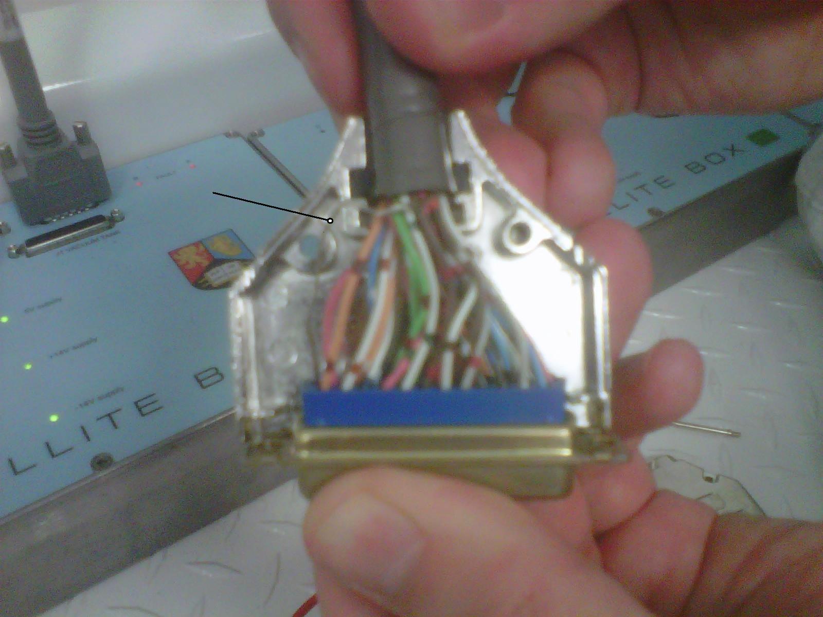
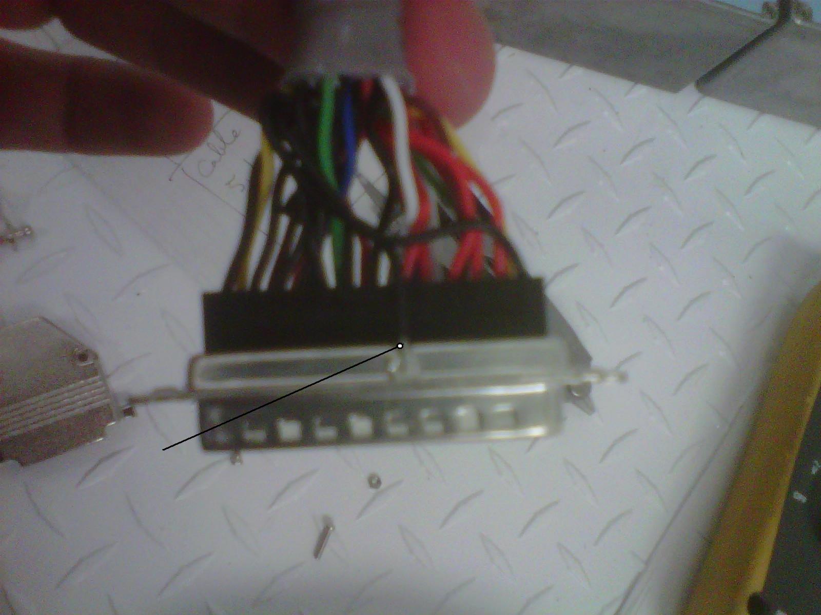
2.  The same SUS cables were then checked to see if pin 13 of each connector was connected to the cable shield as it is supposed to be.  Two cables were found (SUS-1 and SUS-19) without a connection.  We later found out that this was due to poor workmanship on the cable construction as can be seen from the attached photos.  The SUS cable shield connection is made by pinching a short piece of wire precariously between the two halves of the backshell.  This is not a reliable connection.  The ISC cable has a soldered connection from the backshell to the cable shield rendering it far more reliable over time.  We fixed the SUS cable problems by better positioning the shield wire connection between the two halves of the backshell, but it calls into question the reliability of the shield connection for this type of cable.

3. Verified that all cables incident upon the air side vacuum feedthroughs have no connection between the backshell and shield.  A connection here would ground the cable shields once they plug into the vacuum feedthroughs, it would not be apparent until the mock feedthroughs are removed because the mock feedthrough uses a short length of unshielded ribbon cable to achieve the needed mirroring of the pinout.  

4.  For all SUS and ISC cables, we verified that once the airside cable is disconnected, the inside vacuum shields are isolated from ground.  The SEI cables were similarly verified yesterday to be satisfactory with the exception of L4C-2 and L4C-3 as previously noted. 
Images attached to this report
LHO General
patrick.thomas@LIGO.ORG - posted 19:27, Friday 09 March 2012 (2408)
plots of dust counts
Attached are plots of dust counts > .5 microns.
Non-image files attached to this report
H2 General
rich.abbott@LIGO.ORG - posted 18:34, Friday 09 March 2012 (2407)
ETMY Cable Shield Grounding
Today Betsy fixed the ground points in the suspension wiring where the metal backshells of the connectors serving the UIM and PUM were grounded by the saddle clamp.  I will check to see the status of the SUS shield grounds tomorrow.

Vincent and I worked through the ISI cable shields for the L4Cs, GS13s, Coil Drives, and Trilliums.  We found two anomalous grounds, one on L4C-2 and one on L4C-3.  Both of these grounding points were traced to the connectors at each L4C can the vacuum system.  If the connectors are unplugged from the L4C's, then the grounding issue goes away.

I speculate that the ground is caused by the fact that the strain relief screws that attach the backshells of the connectors to the L4C can are bridging the gap between the can and the metal backshell of the connector.  If these screws were screwed in (as they should be prior to inserting the cartridge), the problem may go away.  It's near impossible to get up high enough to test this theory at present, so the final verification will have to be done during the installation of the cartridge when the connectors are more accessible.

The good news is that so far, I have not seen any instances of the cable shields casually contacting the ISI structure as they route all over the place.  There are numerous contact points, but the outer black PEEK weave seems to reliably prevent the shields from grounding.  I was more than a little worried that the larger sample size of cables and contact points would reveal a weakness in my small statistics of reliability.
H2 AOS
keita.kawabe@LIGO.ORG - posted 18:15, Friday 09 March 2012 (2406)
TMS vibration absorber reinstalled

Following advice from Fabrice and Callum, I and Dan rotated them 90 degrees and put them in a (hopefully) correct direction.

We didn't use thick washers between the absorber flame and the base plate, partly because it would have been a pain to do so, partly because the screws available were somewhat short (it didn't go all the way through the base plate) and using washers would have reduced the number of screw threads that were engaged.

Images attached to this report
H2 CDS
david.barker@LIGO.ORG - posted 16:41, Friday 09 March 2012 (2404)
all front ends except PSL running rig 2.4.2

The ISI, HPI and TMS models were fixed and now all the H2 frontends with the exception of the PSL are running RCG2.4.2.

We found a DAC/ADC reconfiguration problem on h2seib8, which Rolf is investigating. I had some timing issues at EY when restarting the SUS frontends, which I cannot reproduce.

SUS FMX will not compile, I've taken it out of the DAQ for now.

X1 SEI
hugo.paris@LIGO.ORG - posted 15:49, Friday 09 March 2012 (2403)
HAM-ISI Unit #2: transfer functions measurement over the weekend

X1 HAM-ISI Simulink model does not have more than 3 ADCs. Earlier today, CDS team confirmed that it was safe to run unattended excitations on HAM-ISIs, in the staging building.

A quick Transfer Function measurement (2h) was performed on HAM-ISI Unit t#2 today. DAC output channels were monitored. No abnormal behavior was observed.

Transfer function measurements, and their excitations, are running on HAM-ISI Unit #2 over the weekend.

H2 SUS
betsy.weaver@LIGO.ORG - posted 15:10, Friday 09 March 2012 - last comment - 18:01, Friday 09 March 2012(2402)
H2 ITMy BSC8 extraction
Today, Travis, Jason and I finished extracting the ITMy lower QUAD structure.  There was a small issue with the elevator controller unit in that it failed to lower all the way.  We addressed this issue by swapping it with the controller from our second elevator setup (having backups is a VERY good thing).  We also encountered some interference between the optic stop "fingers" and the arm, resulting in removing the fingers altogether and reseating the elevator on the QUAD.

The QUAD was removed from the BSC repair arm and inserted into a lower structure storage container for it's flight back to the fiber welding cleanroom in the LVEA.  Currently, it resides in the storage container in an anterior cleanroom awaiting disassembly and a decision on the path forward.  Dale Ingram documented most of the extraction process by camera and his pictures/videos should somewhere sometime.  
Comments related to this report
dale.ingram@LIGO.ORG - 18:01, Friday 09 March 2012 (2405)
Two photos of the extraction are attached.  The collection sits in ResourceSpace.  Rodney Haux shot the preparations on 3/8.  In RS, sort the photos by date (click twice?) and you should see them in the proper order.
Images attached to this comment
H2 CDS
keita.kawabe@LIGO.ORG - posted 19:24, Thursday 08 March 2012 - last comment - 14:55, Friday 09 March 2012(2398)
Ground loops: TMS and ISC are good, SUS and TCS are not

We continued our investigation by disconnecting everything under the ISI table from outside.

As it turned out, all TMS and ISC cables are fine, but using DVM with alcohol-wiped tips we identified problems in SUS BOSEMs and TCS ring heater:

  1. L2 (penultimate mass) BOSEM cable shield,
  2. L1 (second mass from the top) BOSEM cable shield,
  3. Ring heater cable sheild

are all locally (i.e. in-vac) connected to the metal structures, and if you look closely it's really obvious (Rich said "How can this NOT be grounded?!").


ETM/ERM:

The first picture shows the cable connector clamp on the penultimate mass. Can you see that the clamp doesn't have any insulation? It's just two metal plates sandowitching the metal connector shell. Of course the penultimate mass is electrically connected to ISI via suspension wire.

Also, a pinching clamp for the cable (only the bottom half of which is shown at the top of the photo) doesn't have insulation, though the cable itself has an insulation mesh.

I couldn't take a good picture of the L1 connector clamp, but it's the same design.

This is a serious ground loop right there for SUS (but not for ISC and TMS) and we should discuss any possible fix.


TCS:

The second picture shows the elaborately designed cable bracket thingie that directly connects the ring heater cable shell to the mirror cage.


ISI:

We haven't disconnected ISI cables simply because there are many,  and we know that the ISI cables are going to be revisited after the cartridge insertion. But somebody should do that to see if there's some funny thing is going on like SUS and TCS (and ISC/TMS before we fixed one clamp problem).

We just looked around and saw two cable shield rings resting on metal bolt of ISI (third and forth picture).

Images attached to this report
Comments related to this report
betsy.weaver@LIGO.ORG - 14:55, Friday 09 March 2012 (2400)
I was able to sneak out to Ey and disassemble the brackets which were causing the ground fault on the QUAD (SUS ones, not TCS ones).  Rich will continue his "Ohming", but I will need to redress these brackets/connectors.  I have the Reaction chain UIM and PenRe clamped. 
LHO General
jonathan.berliner@LIGO.ORG - posted 16:41, Thursday 08 March 2012 - last comment - 07:27, Friday 09 March 2012(2395)
Thursday Aft Ops Log
[Continuing from Corey]
- Retractable arm inserted on BSC8, H2ITMY Quad removed.
- Many high (10k-30k) dust count alarms in the Biergarten, but the offending dust monitors could not be located. The only dusty activity during much of this time was vacuum cleaning in the area and retractable arm installation by the door of BSC8
- CDS worked on cornering the H2ITMY fiber-breaking issue. Many reboots of h2seib6, h2seib8, and the entire DAQ as code and models were updated.
- H2 PSL and CDS are working into the evening.
- OSB doors locked at 1630.
Comments related to this report
betsy.weaver@LIGO.ORG - 07:27, Friday 09 March 2012 (2399)
In fact, we did not remove the lower QUAD.  The arm was mated to the lower QUAD, but felt that was a good stopping point for the night.  The arm is parked inside the chamber.  
H1 SEI
greg.grabeel@LIGO.ORG - posted 17:30, Tuesday 06 March 2012 - last comment - 15:26, Friday 09 March 2012(2369)
A tale of two pods

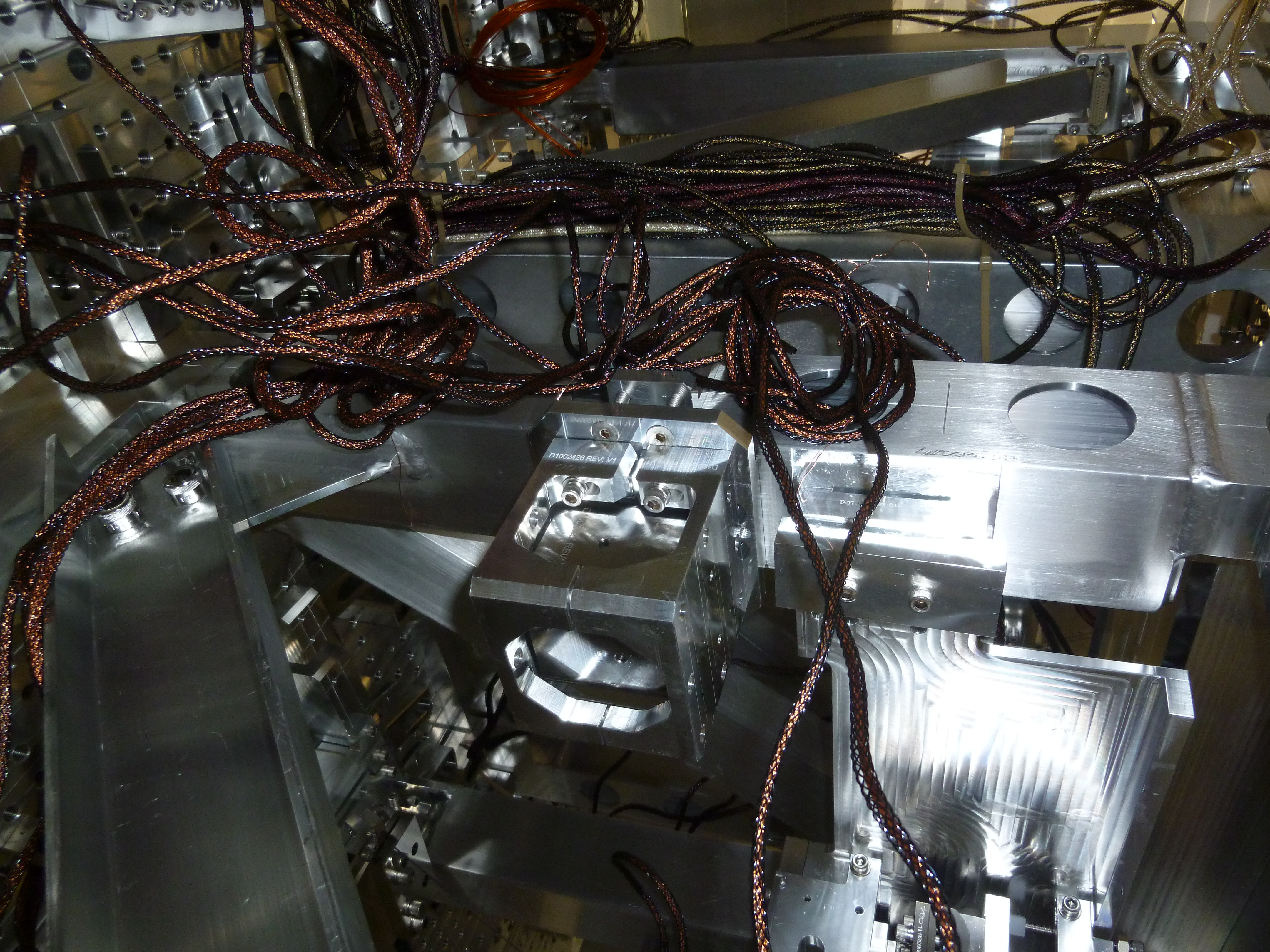
Pods #94 and #71 were experiencing the problems laid out in alogs 2308 and 2321. So today I de-podded both of them. During the de-podding I noticed no issues with the feet or any other kinematic devices.

I did find a broken flexure on #71, however (pictures attached). Which is odd since the GS-13 tested fine on arrival. Somewhere in between its arrival and testing it completely failed. It's possible it was severally fatigued during shipping and only recently failed.

Pod #94 has had its brains swapped with another failed GS-13 (mechanical issues) and will hopefully be tested sometime tomorrow to see if that solves the gain issues. If not that should point us toward some mechanical problem that I haven't seen before.

Both of these pods will become test pods (if their issues can be fixed) until they can be sent to LLO for retesting.

Images attached to this report
Comments related to this report
hugo.paris@LIGO.ORG - 15:26, Friday 09 March 2012 (2401)

A Huddle test was performed earlier this week in order to evaluate the effect of the reparations.

  • Pod #94 does not feature a gain of 1/2 anymore. It confirms that its pre-amp was initially malfunctionning.
  • Pod #71 does not output signal. It did output signal before having its flexure replaced. It is possible that an electronic mis-connection was caused during de-poding/repoding process.

Results and pictures of the test are attached.

Non-image files attached to this comment
Displaying reports 85961-85980 of 88300.Go to page Start 4295 4296 4297 4298 4299 4300 4301 4302 4303 End