Displaying reports 85981-86000 of 88291.Go to page Start 4296 4297 4298 4299 4300 4301 4302 4303 4304 End
Reports until 23:38, Wednesday 07 March 2012
H2 CDS
keita.kawabe@LIGO.ORG - posted 23:38, Wednesday 07 March 2012 - last comment - 00:06, Thursday 08 March 2012(2390)
Cornucopia of (potential) ground loop at EY

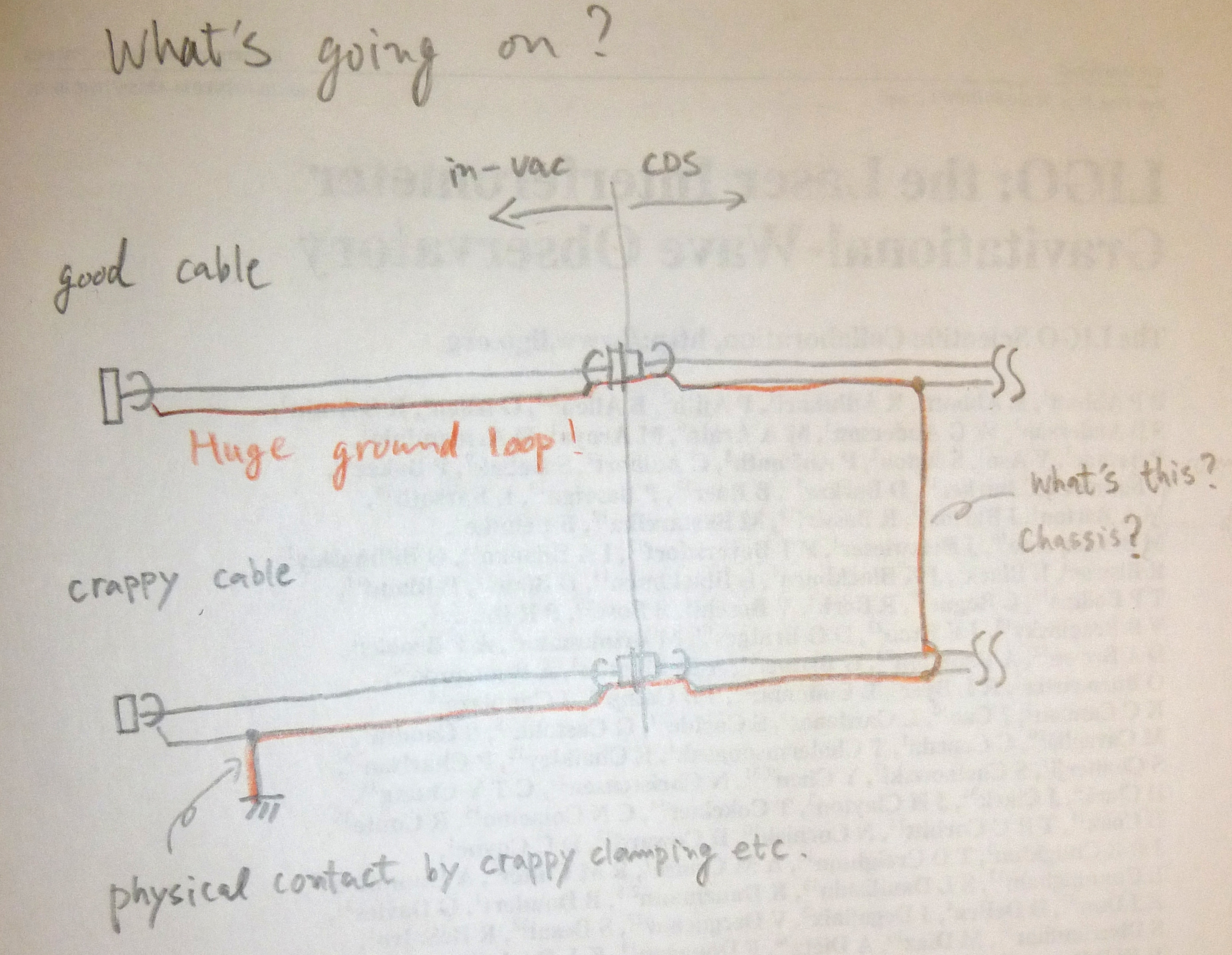
I and Dan confirmed that shells of ALL in-vac cables that are connected to CDS side are grounded to the metal parts of ISI and TMS. I'm talking about all cables related to ETMY, ERMY and TMSY. There is a huge potential risk of ground loop(s).

The cause of this is NOT in four ISC cable chains (picomotor, beam diverter, and two QPD cables). This was confirmed by disconnecting all ISC cable chains from the CDS side at the moc feedthrough: When we did this, the shells of disconnected in-vac cables were isolated from the metal parts of ISI/TMS.

We haven't exonerated the two BOSEM cables of TMS yet, as well as all ETMY and ERMY cables.

What is likely happening here is:

Even though there seems to be no DC-coupled "loop" as far as ISC table/cable is concerned in the above picture, basically the ISC cable shields on the ISC table are within 1/32 inches or so of the table surface for the entire length and there certainly is a capacitive coupling. And if there are two crappy cables, they form DC-coupled loop, even though that's not ISC. This is bad.

One crappy cable might be the cause of the entire thing.  I can continue testing the remaining two TMS cables, but if we're unlucky we might need to check each and every in-vac cable including ETMY, ERMY, TCS and ISI cables, and I need cooperation from all parties.
Images attached to this report
Comments related to this report
keita.kawabe@LIGO.ORG - 23:53, Wednesday 07 March 2012 (2391)

We fixed one crappy cable clamping today.

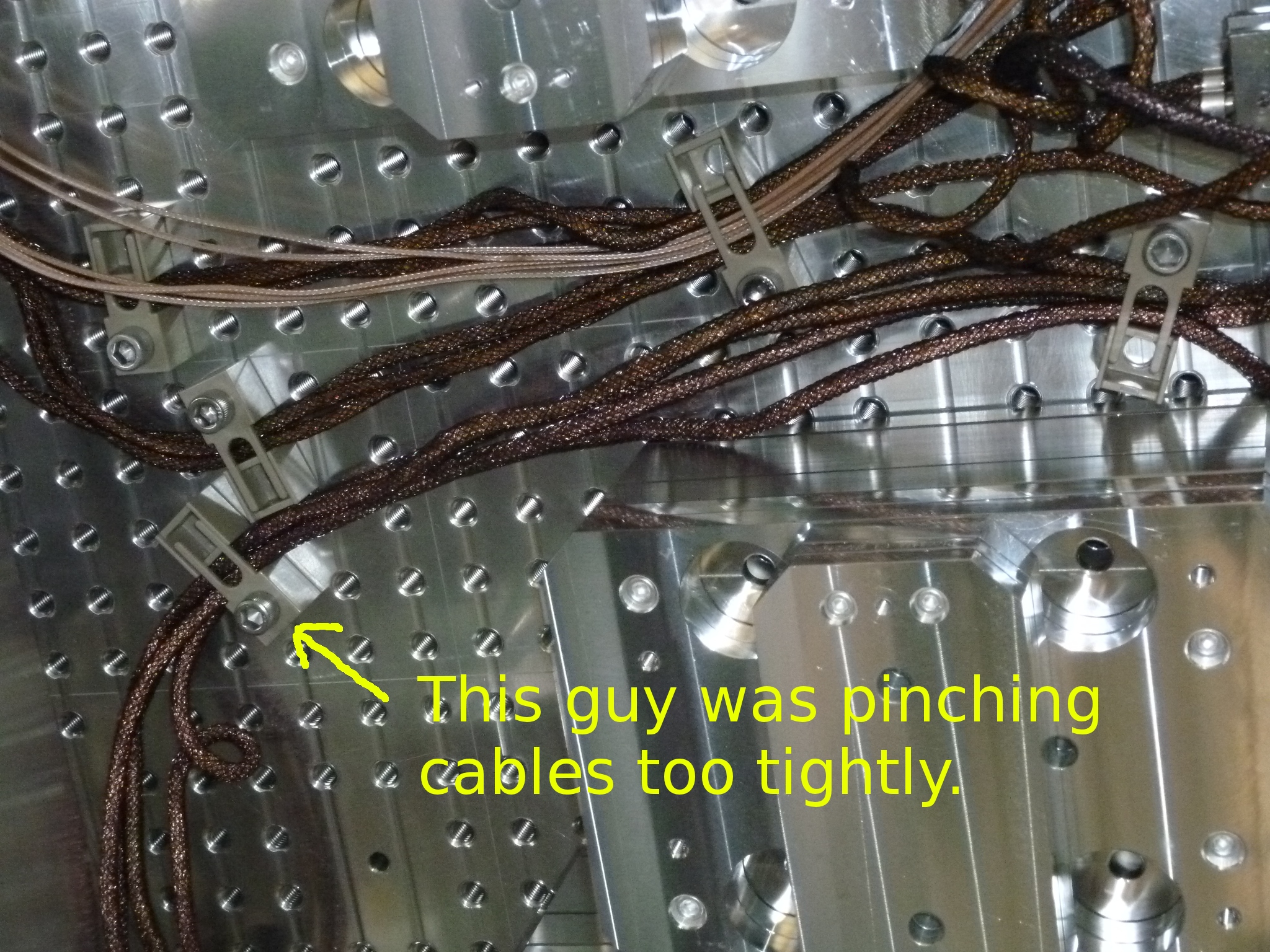
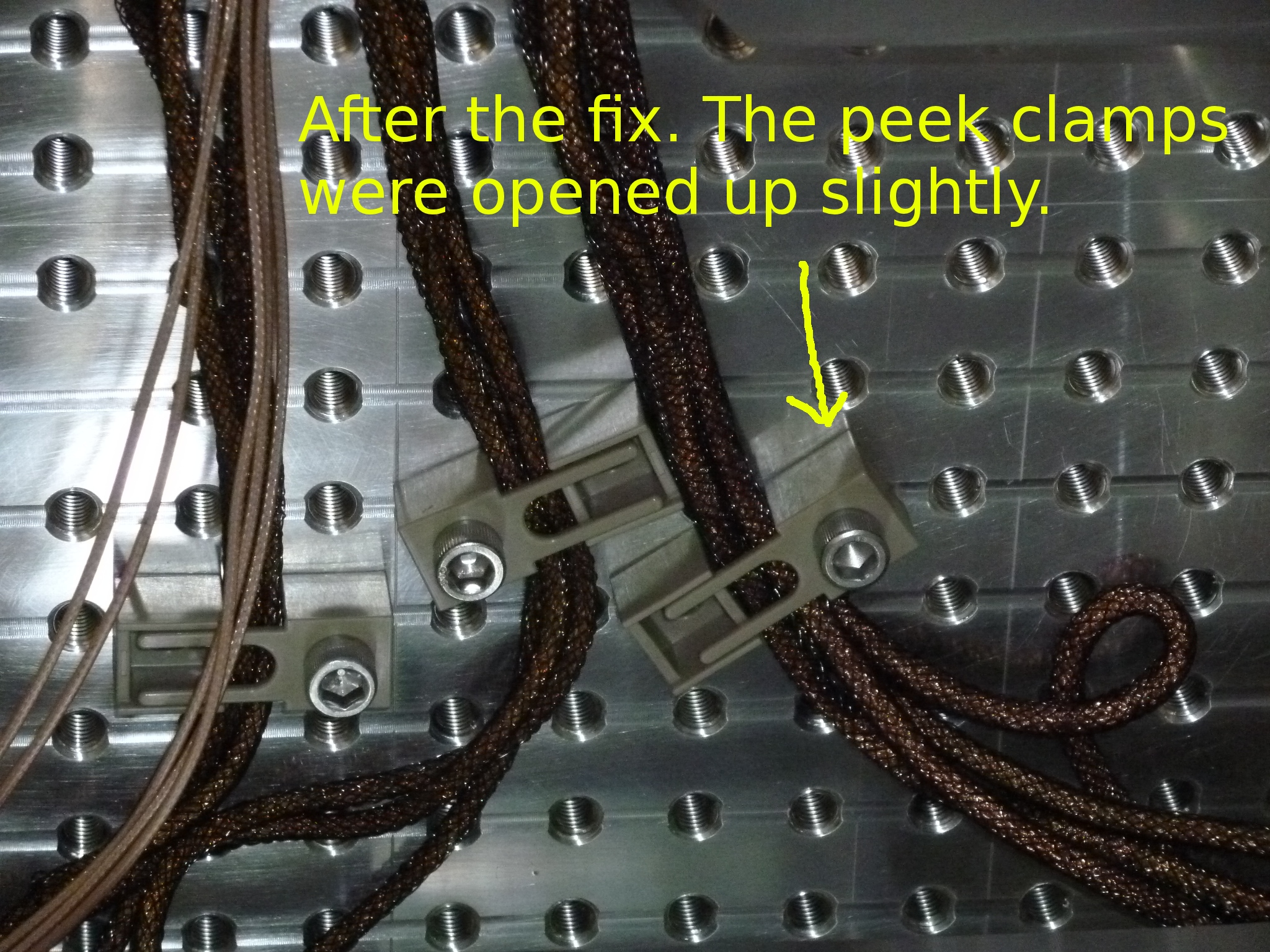
One of the peek cable clamps was squeezing four ISC cables really tightly, and this was causing some problem to the picomotor cable. Either the shielding of the cable was shorted to the shielding of one of the QPD cables, or it was directly shorted to the ISI table. (The symptom was that the shell of the picomotor cable was grounded to the ISI table even though the picomotor cable was not connected to CDS.)

Due to the position of the picomotor cable in this cable clamp, we cannot confidently say which was the case, but anyway once we made the spacing of the peek clamps a bit wider (second picture), the problem was gone.
Images attached to this comment
keita.kawabe@LIGO.ORG - 00:06, Thursday 08 March 2012 (2392)

How is IY? Have SEI/SUS people confirmed that there's no potential ground loop there?
H2 SUS
betsy.weaver@LIGO.ORG - posted 20:23, Wednesday 07 March 2012 (2389)
BSC8 ITMy repair work
After pulling back the ACB and removing a few panels of flooring, QUAD vibration absorbers, sleeve and Fiber Guards we made more inspections of the ITMy weld horns.  The following collection on ResourceSpace is of the shortest broken horn:

https://ligoimages.mit.edu/?c=1002

We do not see any cracks further down into the horn or ear.  We used a swab wipe to brush away some of the debris on this ear in order to facilitate further inspection, hence why some of the pictures may look a little different when compared.
H1 PSL
michael.rodruck@LIGO.ORG - posted 16:53, Wednesday 07 March 2012 (2387)
H1 PSL installation

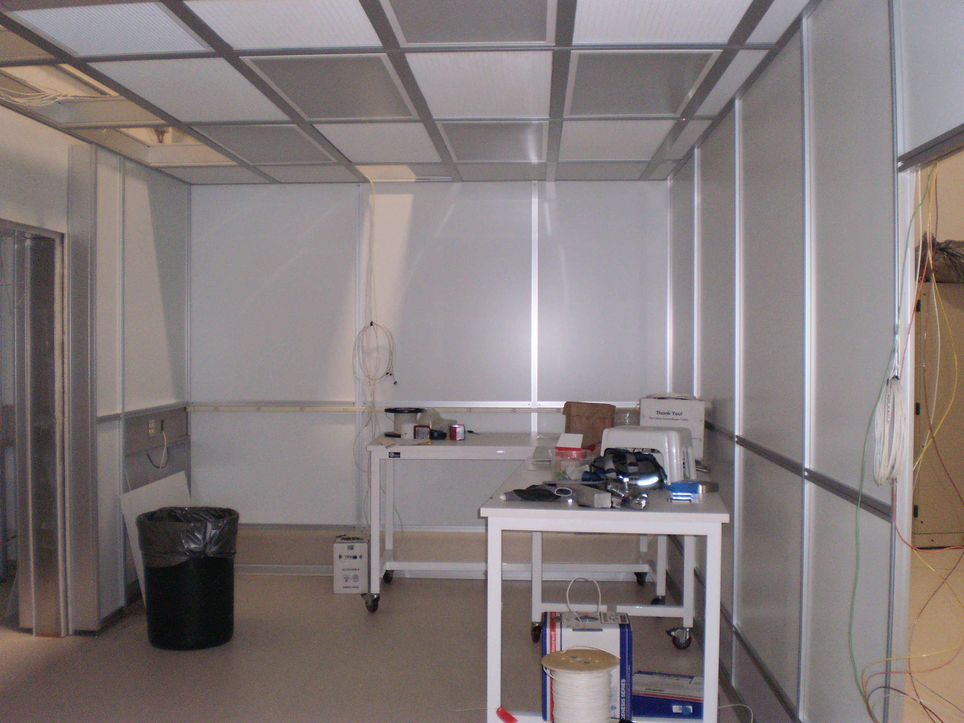
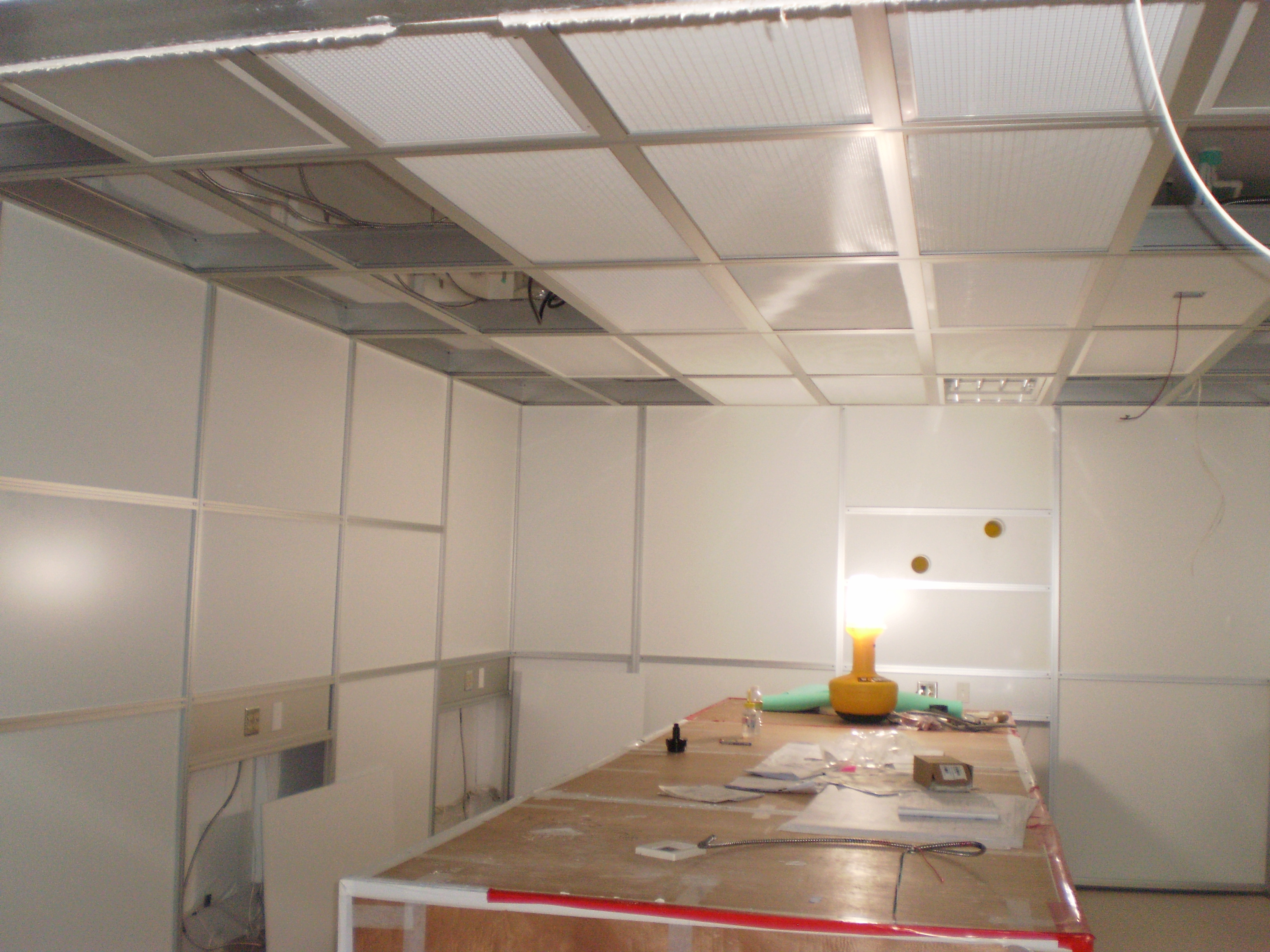
HEPAs are installed, ceiling and several wall panels have been left off for electrical inspection. Gang plates were installed. Gerbig has left but will be coming back in late March.

Images attached to this report
H2 SEI
christopher.kucharczyk@LIGO.ORG - posted 15:54, Wednesday 07 March 2012 - last comment - 16:50, Wednesday 07 March 2012(2384)
Difference between watchdog DQ and EPICS channels
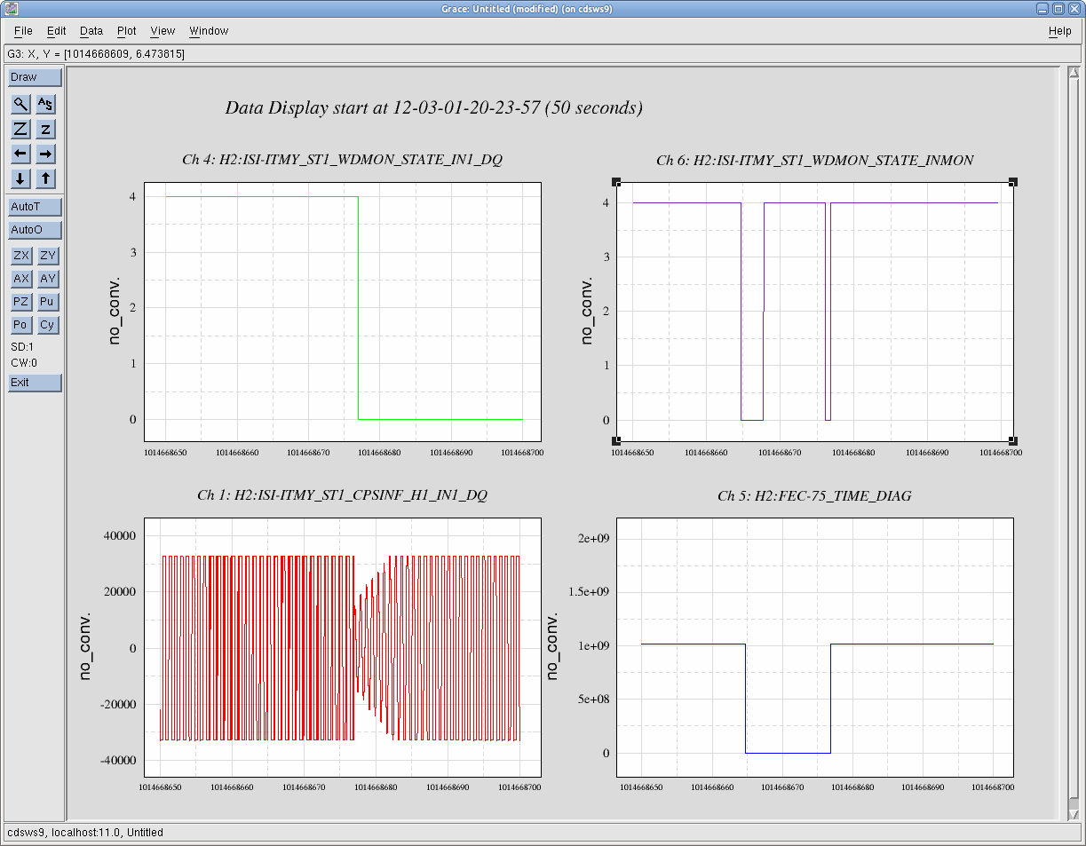
Brian, Fabrice and I have found that there is an odd discrepancy between the value of the watchdog recorded by the framebuilder and the value recorded by EPICS. The EPICS value reads 4, while the framebuilder value reads 0. These should be reading the same value, since they are both a part of the same filter module (H2:ISI-ITMY_ST1_WDMON_STATE). 

In the attached plot, you can see the discrepancy in the top two charts (all full data). The top left is the DQ channel, which says the watchdog is 0 (??), while the top right is the EPICS channel, which says the watchdog is at 4 (fully tripped). The watchdog C code has no '0' state, so it's odd that this value would be recorded at all when the model is running.

We show that the model is running by showing the GPS time as recorded from the model in the bottom right. The value for the GPS time drops to 0 when the model is killed (1014668665) and comes back when the model is started again (1014668677). 

We also get full data from CPS H1 at the bottom left when the model is restarted. The data from 1014668665-677 in this channel is not 'real' - it is reflections of previous data at 1 second intervals. This can be casually observed by the apparent aliasing effect from 1014668655-70 in what look like dark diagonal stripes. We can see the CPS signal grow when the model starts.
Images attached to this report
Comments related to this report
fabrice.matichard@LIGO.ORG - 16:50, Wednesday 07 March 2012 (2386)
The document attached show similar discrepancy between the DAQ and EPICS channels visible in CPS, Seismometer and Watchdogs channels.

The first page show a comparison of 10s full data.

The second page show a comparison of 10mn data, second trends.
Non-image files attached to this comment
H2 SEI
christopher.kucharczyk@LIGO.ORG - posted 15:06, Wednesday 07 March 2012 - last comment - 16:43, Wednesday 07 March 2012(2383)
The beginning of the excitation in the ISI CDMON and IOP DAC
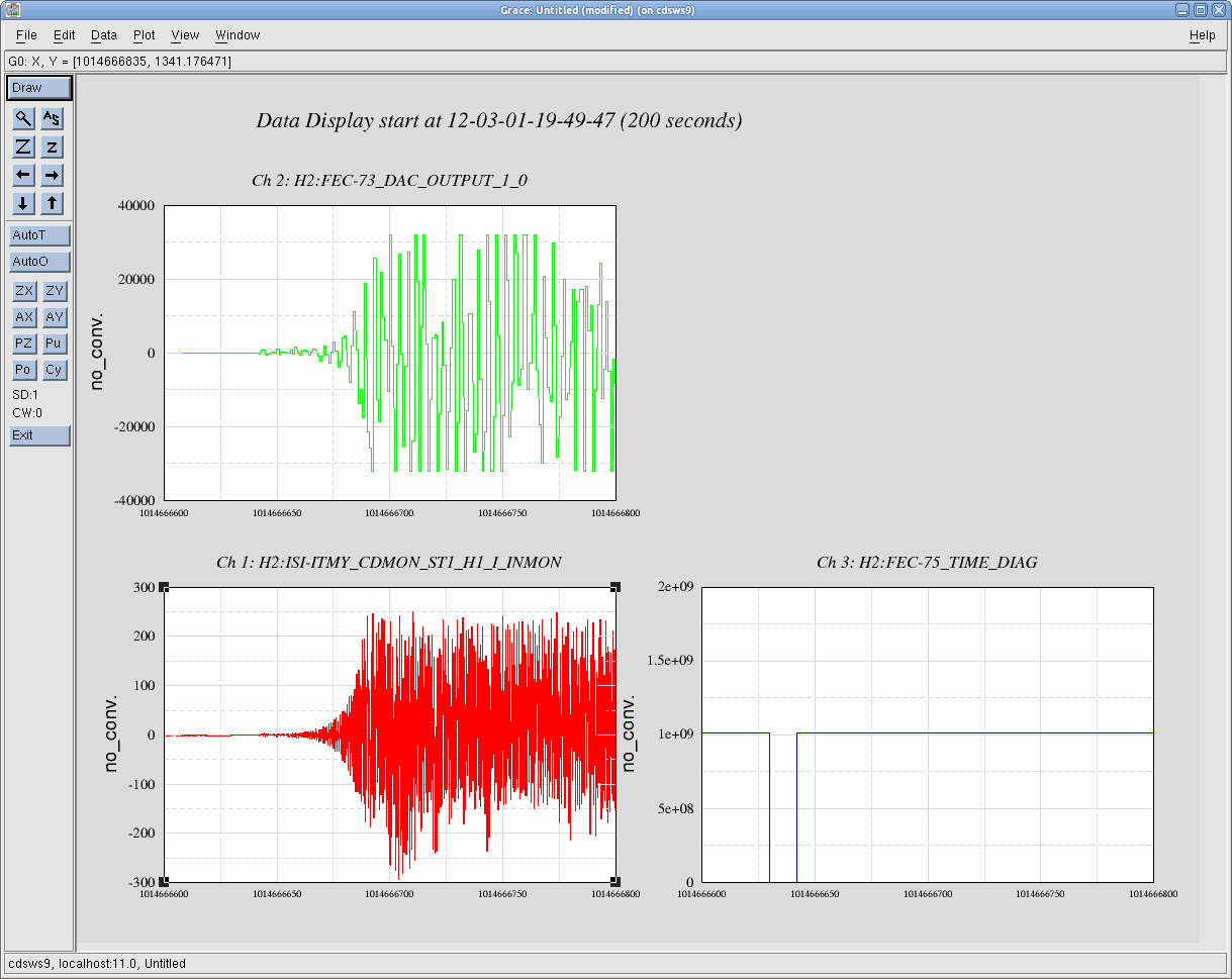
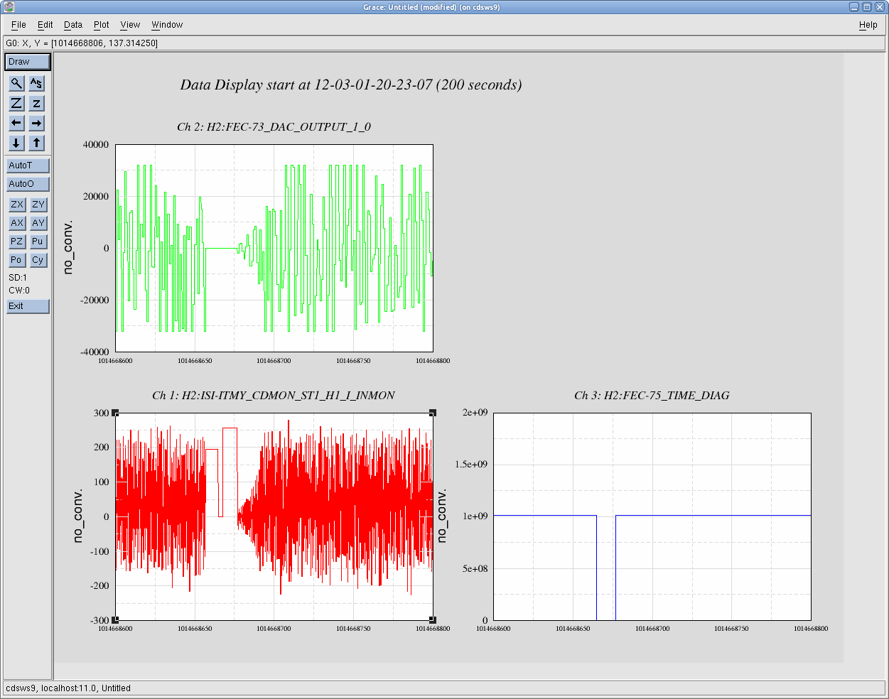
Brian and I have plotted the beginning of the (bad) excitation in dataviewer in both the ISI and IOP models. We have also plotted the GPS time according to the ISI model (DCU_ID 75). As you can see, the GPS time drops out when the model is being off, but comes back up shortly thereafter. This data is for the 11:42 UTC restart when the excitation starts. 

We plot the same for the second restart, twenty minutes after which the fiber break occurs. We see the same thing - the model is shut down, then starts again. We see a similar drop in the GPS time to 0 before the model restarts. The excitations also stop when the model stops, and start again when the model restarts. We see a growth in the amplitude of the coil drive signal as well as the DAC signal from the IOP.

This is not inconsistent with a loop instability within the model.
Images attached to this report
Comments related to this report
christopher.kucharczyk@LIGO.ORG - 16:43, Wednesday 07 March 2012 (2385)
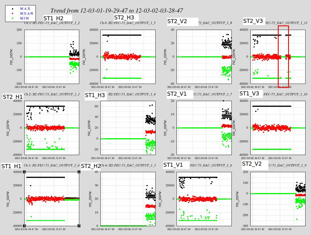
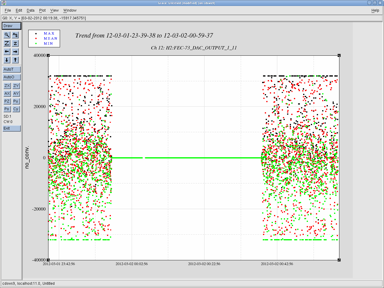
We have also plotted the actual signals that the IOP was driving during the entire event. What's most interesting is that the signals on all channels appear to be max-ed out during the whoe event, except for ST2_V3, which drops out about five or six hours into the excitation, then returns upon a later model rebuild. The signal drops out after the 15:57 PST rebuild and returns after the 16:38 rebuild. Unsure what this entails.
Images attached to this comment
H2 SEI
vincent.lhuillier@LIGO.ORG - posted 12:23, Wednesday 07 March 2012 (2381)
Actuators resistances ISI-BSC8

Yesterday, we measured the resistances of the 12 actuators on ISI-BSC8. The table below shows the measured resistance when the ISI was:

- in the staging building

- on the teststand in the LVEA

- in the chamber (March 6, 2012)


Field cables in the LVEA are about 1 ohm. Resistances measured after the important drive are similar to those measured when the ISI was on the LVEA teststand. There are no obvious signs of damage on these actuators.


  Staging building LVEA Teststand Chamber after large drive
Actuators Resistance (ohm) Resistance (ohm) Resistance (ohm)
ST1 H1 6.4 7.5 7.4
ST1 H2 6.6 7.4 7.4
ST1 H3 6.6 Not measured 7.4
ST1 V1 6.4 7.5 7.5
ST1 V2 6.6 7.4 7.5
ST1 V3 6.6 Not measured 7.5
ST2 H1 10.3 11.3 11.3
ST2 H2 10.3 11.1 11.1
ST2 H3 10.1 Not measured 11.1
ST2 V1 10.1 11.1 11.2
ST2 V2 10.3 11.1 11.2
ST2 V3 10.5 Not measured 11.3
H2 AOS
thomas.vo@LIGO.ORG - posted 11:39, Wednesday 07 March 2012 (2380)
Swing back of ACB in BSC8
Betsy B. Travis S. Thomas V.

After reinstalling the swing back plate and support brackets, we swung the ACB back so that SUS can access the quad somewhat freely.
H1 PSL
michael.rodruck@LIGO.ORG - posted 10:09, Wednesday 07 March 2012 (2378)
PSL plots

200W beam

Non-image files attached to this report
H1 PSL
michael.rodruck@LIGO.ORG - posted 10:09, Wednesday 07 March 2012 (2379)
PSL plots

35W beam

Non-image files attached to this report
H2 SEI
fabrice.matichard@LIGO.ORG - posted 09:38, Wednesday 07 March 2012 (2377)
Calibrated plots of ISI motion
The plots in the document attached show calibrated motion and velocity of the ISI when it reaches the steady state regime that will last for hours and lead to the fiber braking.
Non-image files attached to this report
H1 PSL
michael.rodruck@LIGO.ORG - posted 09:34, Wednesday 07 March 2012 (2376)
H1 PSL installation

Ed (Apollo), Michael R

Ducting for the exhaust air path was installed yesterday. Installation is not complete, as we are waiting on some parts, and I still need to caulk the penetration into the enclosure.

H2 AOS
keita.kawabe@LIGO.ORG - posted 09:33, Wednesday 07 March 2012 (2375)
TMS ISC table is grounded to the cable shells

After swapping the picomotor cable, I and Dan Hoak proceeded to check the grounding. To our disappointment, the ISC table is grounded to three of the four cable shells.

We disconnected all four cables connecting the ISC table to the bracket on the ISI table, and tested the grounding of the ISC table to the on-ISC-table cable shells (there are four), and they're fine.

Somewhere downstream, shielding of one or more cables should be touching the metal part of the TMS or ISI, and of course the ISC table is electrically grounded to any of these structures. We need to check cable clamps and copper wires used for bundling the cables.

H2 ISC
keita.kawabe@LIGO.ORG - posted 09:21, Wednesday 07 March 2012 (2374)
TMS picomotor cable was swapped
On Tuesday 06/Mar/2012, we pulled one of D1000223 cables (S1104079, used for picomotors, connecting the feedthrough and the connector bracket on the ISI table) and replaced with  S1104077, which is from a different bake batch. Now all picomotors work.
We tested the bad cable using a cable tester. It tested fine at first, but when I wiggled the cable near the connector I was able to repeatedly make it fail.
Richard wants to test this cable using HV mode of the tester.
 
History of this signal chain (also read https://alog.ligo-wa.caltech.edu/aLOG/index.php?callRep=2350):
LHO VE
david.barker@LIGO.ORG - posted 09:00, Wednesday 07 March 2012 (2373)
vacuum epics data gap from LVEA X arm

Late entry from Monday morning.

We had a network disconnect from the LX vacuum controls system. This was tracked to a bad ethernet cable in the LVEA and it was replaced. The data gap was of the order of an hour. Only h0velx was affected.

H2 SUS
betsy.weaver@LIGO.ORG - posted 08:50, Wednesday 07 March 2012 (2372)
BSC6 Cartridge Plan - next few days
At this mornings meeting, it was decided that Keita would add the locking mechanics to the TMS in order to lock it and continue investigating cable and grounding issues.  Once the hardware issues are settled, the locking hardware will be removed and SUS/SEI testing can commence.
H2 CDS
david.barker@LIGO.ORG - posted 08:44, Wednesday 07 March 2012 (2371)
first draft of CDS status at the time of the ITMY breakage in DCC document

A detailed description of the CDS front ends controlling BSC8 at the time of the fiber breakage has been submitted to DCC as document: LIGO-T1200123

https://dcc.ligo.org/cgi-bin/private/DocDB/ShowDocument?.submit=Number&docid=T1200123&version=

there is sufficient detail in this report that I did not want to submit a huge alog entry. Later I'll also submit a tar file of the front end models and related files covering this time period.

H2 SUS
betsy.weaver@LIGO.ORG - posted 22:18, Tuesday 06 March 2012 (2370)
BSC8 ITMy repair work
(Bland, Sadecki, Shankle, Jodi, Apollo-ers)

This morning, the BSC8 South door was pulled.  Taking care to set down foil stepping stones on the rubble laden flooring in the chamber, I worked my way towards the ITMy shooting pictures along the way.  Travis also entered the chamber for inspection.  We've started 3 libraries of pictures on ResourceSpace, detailed below.

Floor debris from the glass fibers:
https://ligoimages.mit.edu/?c=992

General chamber pictures of ACB and ITMy:
https://ligoimages.mit.edu/?c=991

Some metal shavings were found on the top of the ACB - likely shaken loose from the rogue EXC, but left behind from the Stage 0 hole tapping which occurred during the initial ACB installation.  More notes on this in a subsequent alog.  These metal shavings may or may not be the cause of the fiber breakage, although they are in the vicinity of the fibers.  We hope to do a more thorough search tomorrow for more metal flakes on the ITMy suspension.  At first pass, the 14 collected metal bits were found on the ACB top surface, while none were observed on the flooring of the chamber.

ITMy ears and horns:
https://ligoimages.mit.edu/?c=990

2 of the 8 horns at the base of the fibers have broken off a bit low.  SUS is evaluating rewelding on these horns.

After inspection the following steps were performed:
- With tweezers, we picked up the largest bits of glass stock and fiber and collected them in petri dishes while searching for other non-glass debris.  Only one fleck of metal and a few cloth type fibers were found besides the glass debris.  The one fleck of metal was found many feet from the ITMy, back and to the NE of the FMy SUS.
- The floor was wiped from back to front, pulling most of the glass particulate out towards the door.  Wet wipes were used.  More wiping will be needed.
- The ISI was locked down by Jim, from underneath the ISI table (standing on a stool on flooring in chamber).
- The BSC repair arm and all of it's associated hardware was mounted to the door flange.
H2 SUS
jeffrey.garcia@LIGO.ORG - posted 19:28, Tuesday 06 March 2012 (2366)
H2 SUS ITMY during fiber break
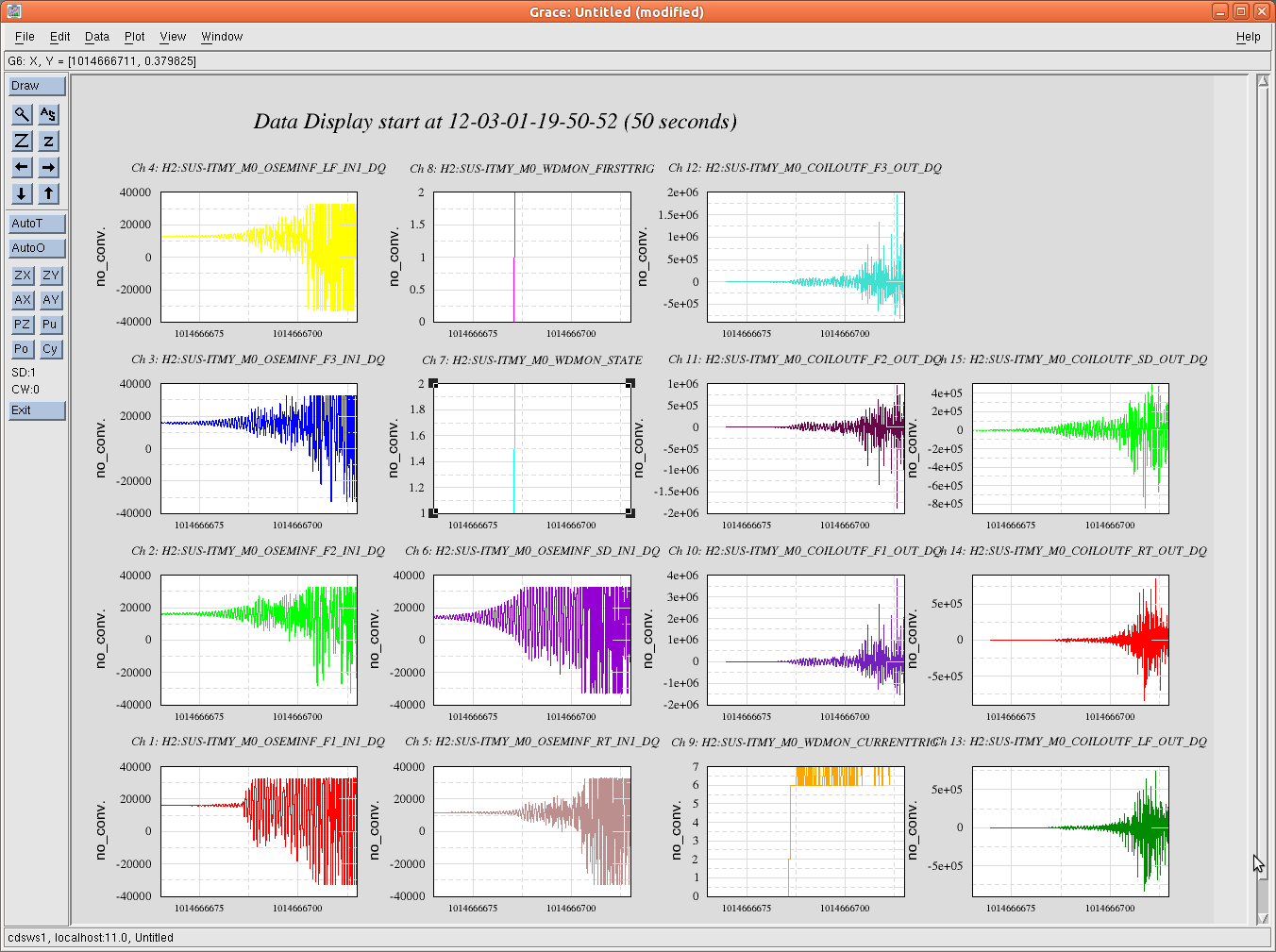
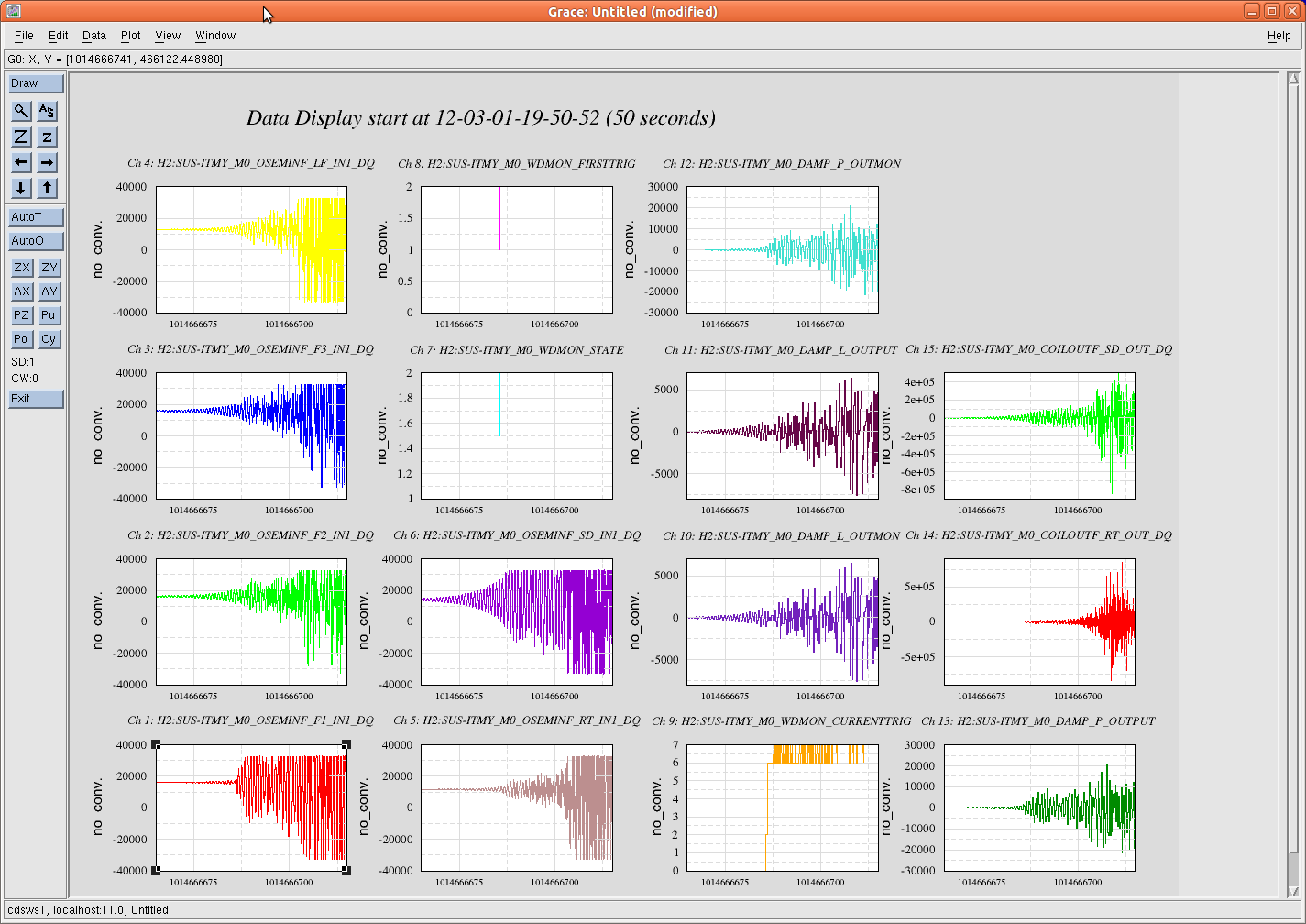
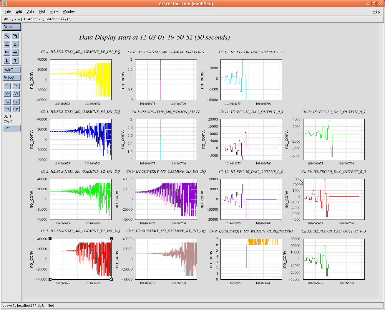
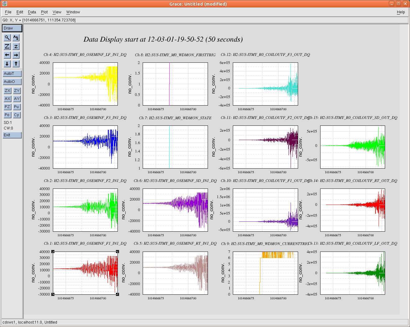
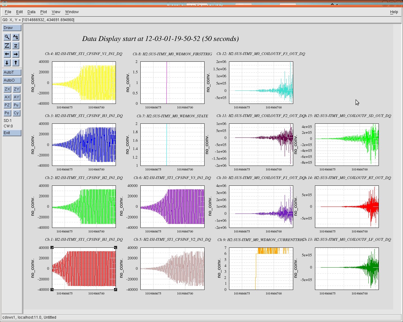
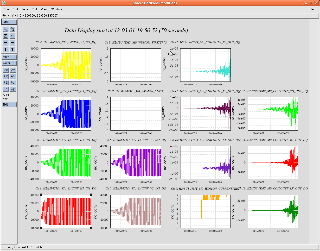
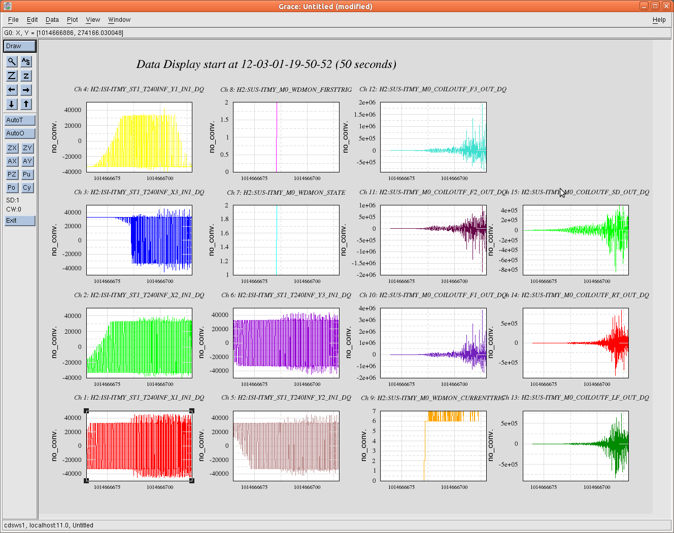
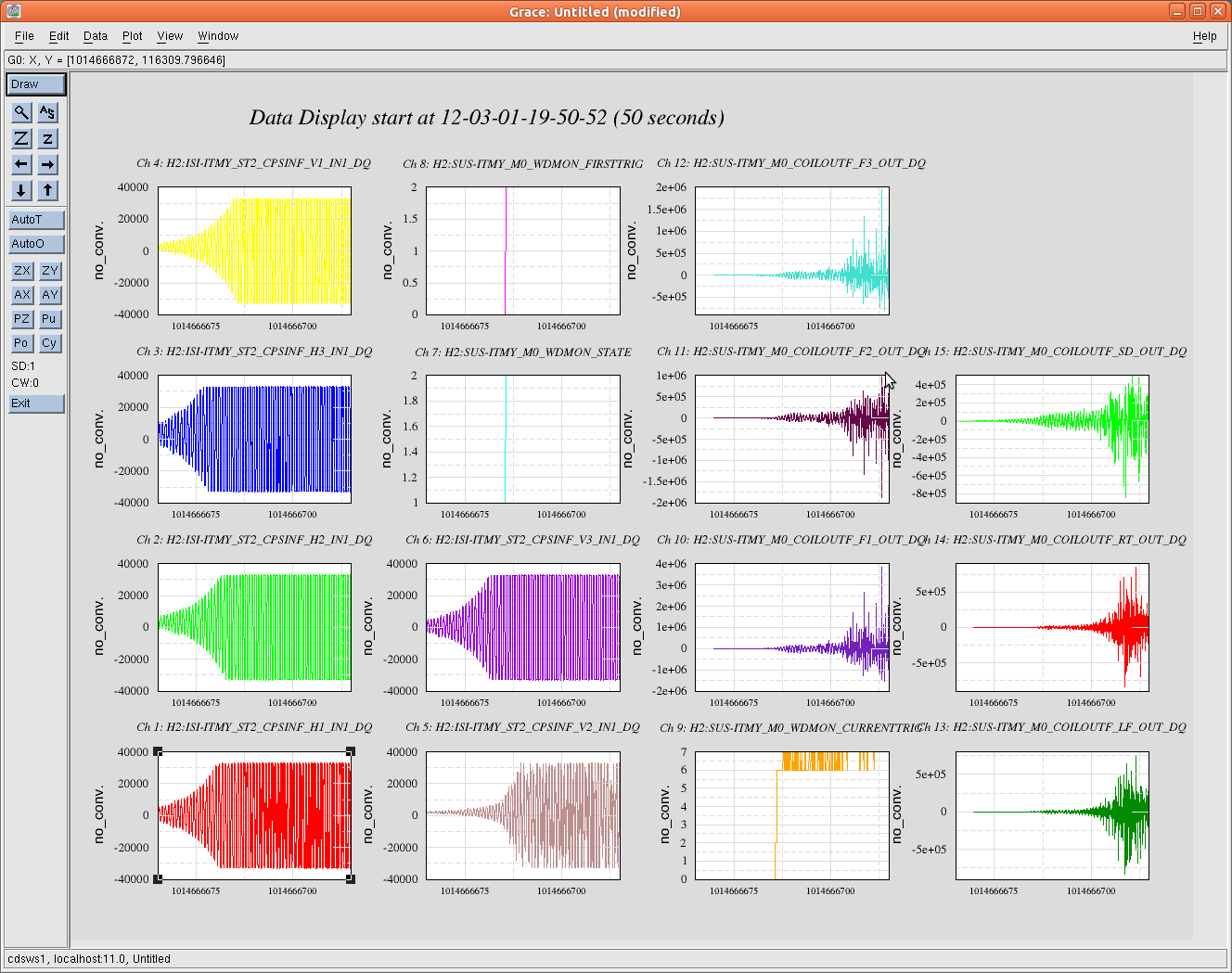
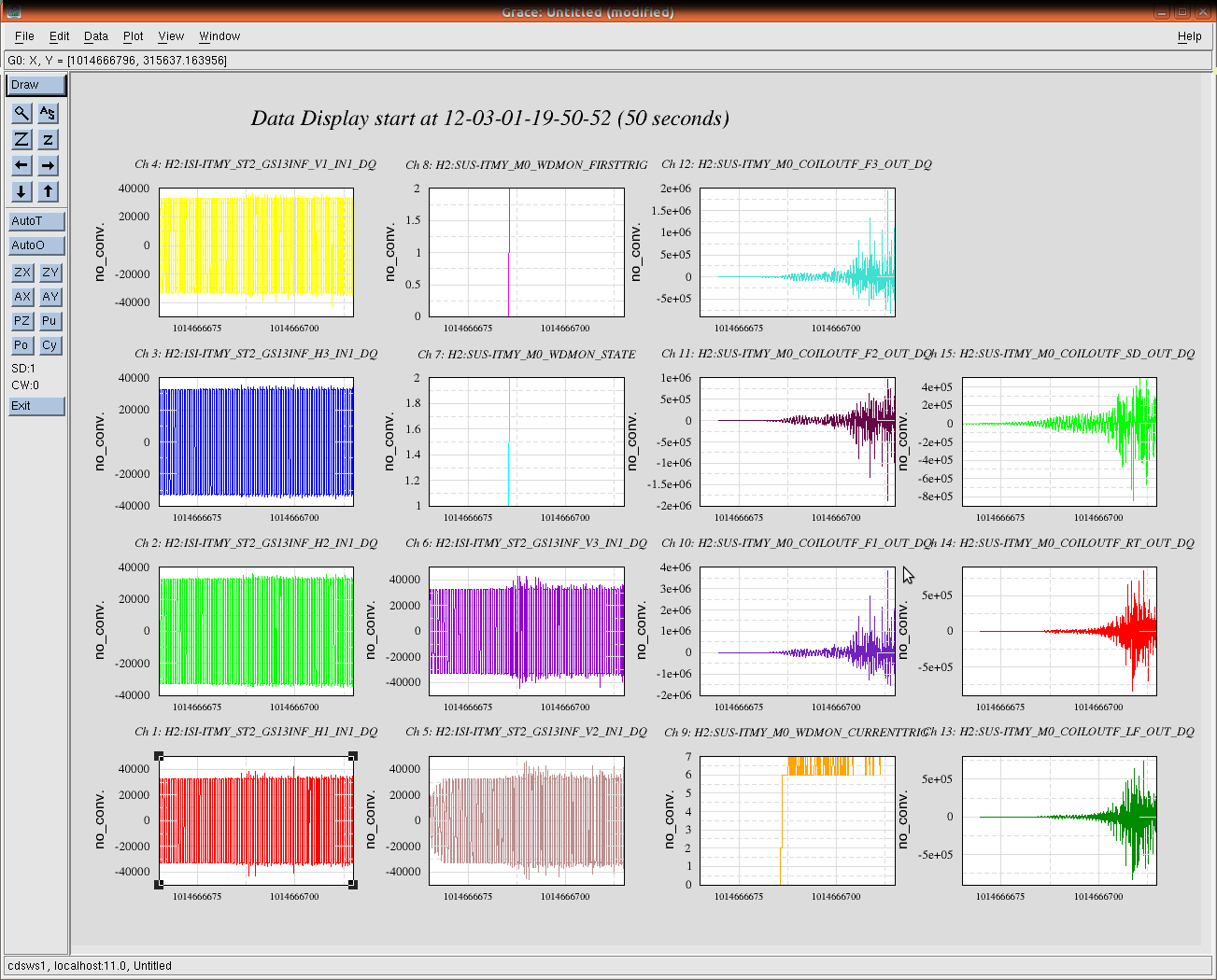
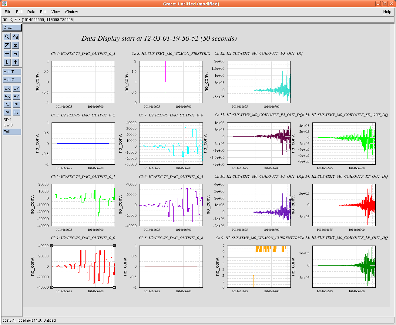
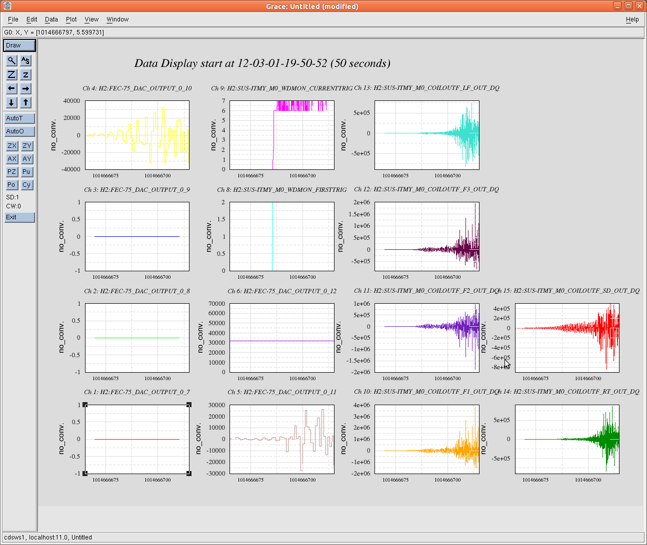
The attached plots are detailed data trends for all input and output channels on the H2 SUS ITMY M0/R0 top masses and each stage of the BSC-ISI during a 50-second period last Thursday March 1 beginning at approximately 11:50:00 PST (UTC: 19:50:00 , GPS: 101 466 6670) until the trigger of the SUS ITMY software watchdogs. 

Some notes before diving into these trends:
1.) The first trigger of the SUS ITMY WatchDogs was at approximately:
    101 466 6686 GPS
    19:51:11     UTC
    11:51:11     PST
2.) These plots all contain 50 seconds of full frame data for those channels with data being written to frames.  Each attachment has a plot of the three SUS ITMY WatchDog states when they first tripped at approximately (GPS) 101 466 6686.

3.) The FEC channels are the EPICS data from the DAC outputs for either the SUS or SEI machines (h2susb478 and h2seib478), which is sampled at 16Hz.  These signals should be the outputs sent to coil drivers.

4.) Each attachment is a different set of either inputs or outputs for each sensor/actuator group on either the BSC-ISI or the ITMY M0/R0 top mass coils. This is true for about the first six plots on each attachment - the SUS WDs and M0 COILOUTF channels were kept while trending different sensor/actuator groups.  

-----------------------------------------------------------
Attachments:
1.)  M0 OSEMINF, M0 WatchDog states, M0 COILOUTF (DAQ data written from output of SUS coil drivers)

2.)  M0 OSEMINF, M0 WatchDog states, M0 DAMP OUTMON (epics 16Hz data)

3.)  M0 OSEMINF, M0 WatchDog states, FEC-30 DAC OUTPUT (DAC machine generating the ITMY coil output signals)

4.) R0 OSEMINF, M0 WatchDogs, R0 COILOUTF

5.) ISI ST1 CPS inputs

6.) ISI ST1 L4C inputs

7.)ISI ST1 T240 inputs

8.) ISI ST2 CPS inputs

9.) ISI ST2 GS13 inputs

10.) ISI FEC-75 (h2seib478 DAC output channels - first half of channels)

11.) ISI FEC-75 (h2seib478 DAC output channels - second half of channels)

--------------------------------------------------------

From these trends, one can deduce several points about which system was actuating just before the break of the ITMY fibers:
1.) The SUS ITMY M0 and R0 damping filters were CLOSED and damping the top masses during the moments leading to the break.

2.) There was excessive motion seen on ALL SUS ITMY M0/R0 OSEMS and each sensor group of both stages of the BSC-ISI.

3.) The SUS ITMY M0 Watchdogs tripped and cut off the output of the DAC signal from h2susb478.  

4.) The ISI DAC machine (h2seib478) was outputting signals on at least 6 of it's outputs.  The exact corresponding ISI channels are not apparent, but the DAC FEC data shows which specific DAC channel had a signal. This indicates the exact actuators with input signals cannot immediately be determined, but not impossible.   

5.)  The ISI Watchdogs were triggered and turned off the "*_MASTER_SWITCH_*".  However, a residual signal was present on the ISI's DAC outputs after the WD tripped.


Images attached to this report
Displaying reports 85981-86000 of 88291.Go to page Start 4296 4297 4298 4299 4300 4301 4302 4303 4304 End