david.barker@LIGO.ORG - posted 10:10, Wednesday 30 October 2024 (80941)
Wed CP1 Fill
Wed Oct 30 10:05:26 2024 INFO: Fill completed in 5min 23secs
Images attached to this report
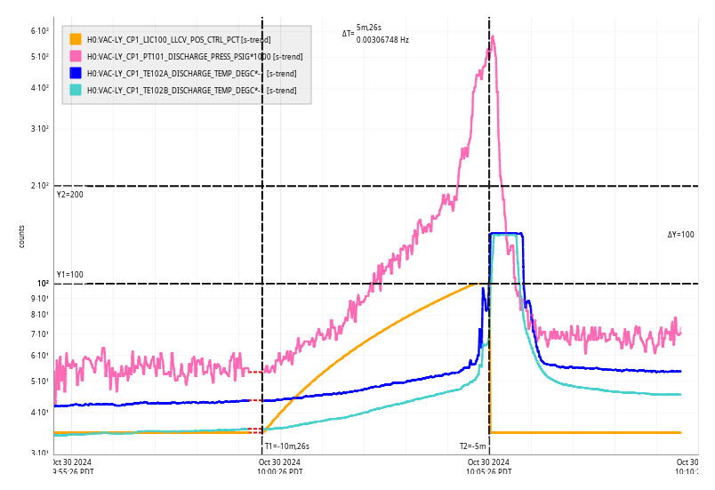
Wed Oct 30 10:05:26 2024 INFO: Fill completed in 5min 23secs
Lockloss @ 10/30 16:09 UTC. Once the lockloss tool analysis finishes we will see if this is because of the gain redistribution and if we have been able to purposely make the FSS glitches reappear (80938).
17:58 Observing
I don't see any glitches before the lockloss and ASC_AS_A lost lock the normal ~250ms before the IMC.
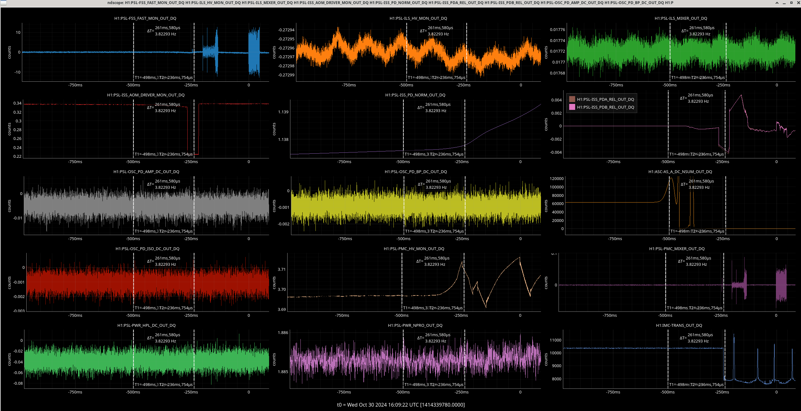
I manually adjusted the IMC IN1 + IM2 gains and IMC fast gain, so that IMC IN2 gain is back to -29dB and IMC FAST GAIN is -16dB, and set the guardian to do this for our next locks in the LASER_NOISE_SUPPRESION state.
Some history:
On the 12th of September, Jim, Daniel and I redistrbuted gains in the IMC CM servo to increase the range it would have to avoid saturating at split mon during times of high ground motion 79998. Starting of the 17th of September we started to have locklosses with large glitches visible before the lockloss in the FSS fast mon channel, tagged as FSS oscillation by the lockloss tool, which became more frequent over time, and these locklosses also have the IMC loosing lock at the same time as the IFO, which did not happen earlier in O4. October 9th Camilla found that the gain redistribution corresponded with the start of the locklosses where the IMC loses lock at the same time as the IFO, 80561, so we reverted the change. At first this seemed to help us have longer locks, but over time the locklosses again became more frequent. After the change was reverted we do not see the signature of the glitches happening in the FSS channel as clearly, so we've been relying on the new IMC tag that Camilla added to the lockloss tool.
Now that the NPRO has been swapped, we still saw 6 locklosses overnight with the IMC tag, lockloss website. These do not have the large glitches in the FSS fast mon channel, but we wanted to try reverting the gain slider change to see if the glitches with the new NPRO appear in the same way that they appeared with the old NPRO and when the CARM loop has more actuation range. We don't expect this to help us stay locked longer, it may make the locks shorter, but we hope to learn something from it and will probably undo the change once we get a couple of locklosses.
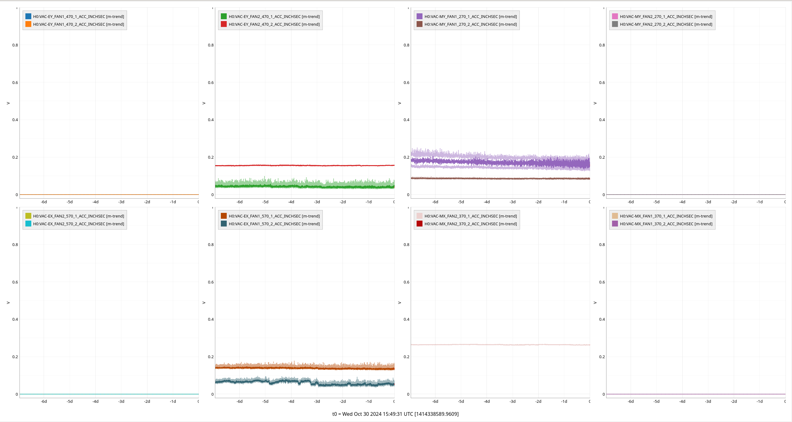
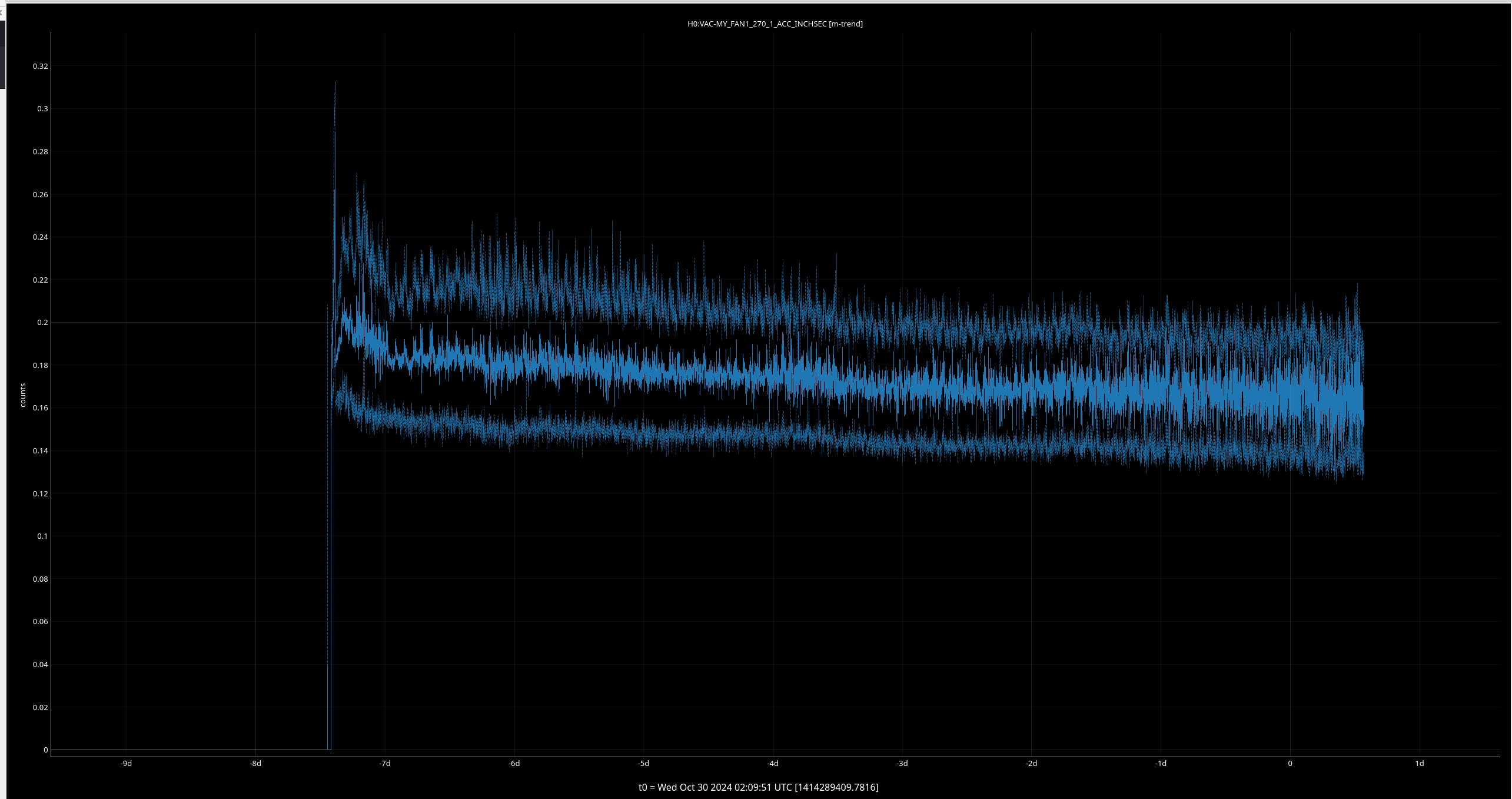
For the OUT buildings MY_FAN1_270_1 seems like its average motion has been growing since it was turned on ~7.5 days ago.
For the CS buildings MR_FAN1_170_2 has gotten noisier over the past 20 hours or so. FAN6 also looks to be getting noisier.

Laser Status:
NPRO output power is 1.887W (nominal ~2W)
AMP1 output power is 68.04W (nominal ~70W)
AMP2 output power is 139.0W (nominal 135-140W)
NPRO watchdog is GREEN
AMP1 watchdog is GREEN
AMP2 watchdog is GREEN
PDWD watchdog is GREEN
PMC:
It has been locked 0 days, 21 hr 22 minutes
Reflected power = 17.34W
Transmitted power = 109.9W
PowerSum = 127.2W
FSS:
It has been locked for 0 days 1 hr and 23 min
TPD[V] = 0.8643V
ISS:
The diffracted power is around 2.5%
Last saturation event was 0 days 1 hours and 23 minutes ago
Possible Issues: None reported
TITLE: 10/30 Day Shift: 1430-2330 UTC (0730-1630 PST), all times posted in UTC
STATE of H1: Lock Acquisition
OUTGOING OPERATOR: TJ
CURRENT ENVIRONMENT:
SEI_ENV state: CALM
Wind: 7mph Gusts, 5mph 3min avg
Primary useism: 0.02 μm/s
Secondary useism: 0.44 μm/s
QUICK SUMMARY:
Looks like an initial alignment just finished. We are relocking and at FIND_IR
TITLE: 10/30 Eve Shift: 2330-0500 UTC (1630-2200 PST), all times posted in UTC
STATE of H1: Observing at 153Mpc
INCOMING OPERATOR: TJ
SHIFT SUMMARY:
IFO is in NLN and OBSERVING as of 01:51 UTC (with a brief drop for cal sweep from 04:21 to 04:58 UTC)
Today we reached Nominal Low Noise for the first time since the PSL NPRO Swap (alog 80929) Corrective Maintenance downed H1 last week (10/22). Despite warnings of a rough shift due to first-time recovery, the IFO must've missed being locked because we were able to lock to NLN and get into OBSERVING by early evening!
The first lock acquisition was short, losing lock seemingly to the IMC at 00:39 UTC, after only 33 mins of NLN and 10 mins of OBSERVING. Lockloss alog 80932.
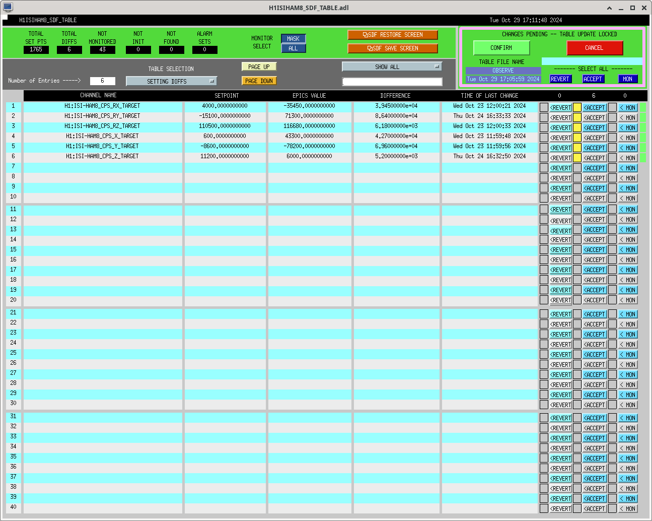
There were some SDF Diffs, mostly TCS-related with some HAM8 Related. After talking to the relevant people, TJ dealt with the TCS ones while Jim told me to accept the HAM8 ISI ones (attached screenshot).
The second lock acquisiton was fully automatic, and only took 1hr 12 mins to lock, which is good even by non-maintenance standards!
A calibration sweep was done (dropping out of OBSERVING for 30ish mins) with a thermalized IFO - alog 80933
Today also marks the first day of triple interferometer (H1, L1, V1) observing since OCTOBER 10.
LOG:
None
Calibration Sweep (done with Wiki Instructions) during first oppurtunity of thermalized IFO since NPRO Swap.
Broadband Start Time: 141297477
Broadband End Time: 141297800
Simulines Start Time: 141297878
Simulines End Time: 141299300
Files Saved:
2024-10-30 04:54:42,097 | INFO | File written out to: /ligo/groups/cal/H1/measurements/DARMOLG_SS/DARMOLG_SS_20241030T043058Z.hdf5
2024-10-30 04:54:42,104 | INFO | File written out to: /ligo/groups/cal/H1/measurements/PCALY2DARM_SS/PCALY2DARM_SS_20241030T043058Z.hdf5
2024-10-30 04:54:42,109 | INFO | File written out to: /ligo/groups/cal/H1/measurements/SUSETMX_L1_SS/SUSETMX_L1_SS_20241030T043058Z.hdf5
2024-10-30 04:54:42,114 | INFO | File written out to: /ligo/groups/cal/H1/measurements/SUSETMX_L2_SS/SUSETMX_L2_SS_20241030T043058Z.hdf5
2024-10-30 04:54:42,119 | INFO | File written out to: /ligo/groups/cal/H1/measurements/SUSETMX_L3_SS/SUSETMX_L3_SS_20241030T043058Z.hdf5
Note: I started the measurements themselves at 2hrs 40 mins after MAX_POWER (due to EVE -> OWL auto-shift transition taking place in this time, so needed to be in OBS by end of shift - ran this by comissioners). IFO hit the 3 hr "thermalized" threshold during the simulines measurements.
Lockloss occured after our first NLN lock acquisition since the NPRO swap. Total time in NLN was 33 mins and the Lockloss Tool is giving an IMC flag.
After LHO's BBSS drift issues was "fixed" by lowering the blades by -4mm from nominal, we noticed that the PUM flags were low and somewhat too low even at their max adjustment. One of the ways to try and fix this was to increase the entire BBSS by 5mm. This maintains the Top Mass blade heights while raising the PUM flags into a centerable position for the PUM BOSEMs.
We increased BBSS Height Increased by 5mm, bringing the PUM flags back to nominal. Once this was done, we needed to move the Top Mass tablecloth upwards to compensate, so we did (by 5mm as well). Below is a table with the Mass-to-Structure gaps. Take note that the Top Mass Gap isn’t an absolute measurement since the tablecloth/structure it is measured from can also move.
|
Date |
Dummy Test Mass Gap |
PUM Gap (mm) |
Top Mass Gap (mm) |
Context |
|
Nominal Dimensions (DWG) |
25 |
17 |
19.90 |
Nominal - what the drawings in D1900628 tell us. |
|
Feb 22 2024 |
25 |
14-15 |
17-18 |
First article build measurement (pre-drift investigation). |
|
Oct 17 2024 |
20.5 |
12.5 |
18.55 |
After “fixing” drift by lowring Top Mass blades -4mm BP (nominal blade position) |
|
Oct 29 2024 |
25.5 |
17.5 |
21 |
After raising entire BBSS by raising Top Stage Blades +5mm |
J. Oberling, R. Short
Today was spent recovering the PSL stabilization systems after we got the amplifiers up and running yesterday.
PMC
We started with the PMC. We did a quick alignment check at lower power (turned down with the High Power Attenuator (HPA) after Amp2) and all looked good here. The power incident on the PMC was slowly increased to max, which we measured at 130.1W with our roving power meter. The PMC ramp was activited and we say TEM00 flashes, so we hit the lock button and it locked without issue. It only had ~100W in transmission so the alignment was tweaked with the picos and we also tweaked the pump diode currents for the amplifiers. In the end we had 108.7W in transmission and 21.5W in reflection, and were running Amp1 at 9.0A and 8.8A and Amp2 at 9.1A (both power supplies). The alignment onto the PMC locking PD was tweaked and we took a visibility measurement (correctly accounting for the 0.015V of dark voltage on this PD):
The PMC throughput was calculated at (Pout/Pin) 83.6%. We also calibrated the PMC Trans and Refl PDs. From the shape of the reflected spot we know there's more mode matching work to do with the PMC, but we have no shortage of power available to the IFO as is so we moved on to recovering the ISS.
ISS
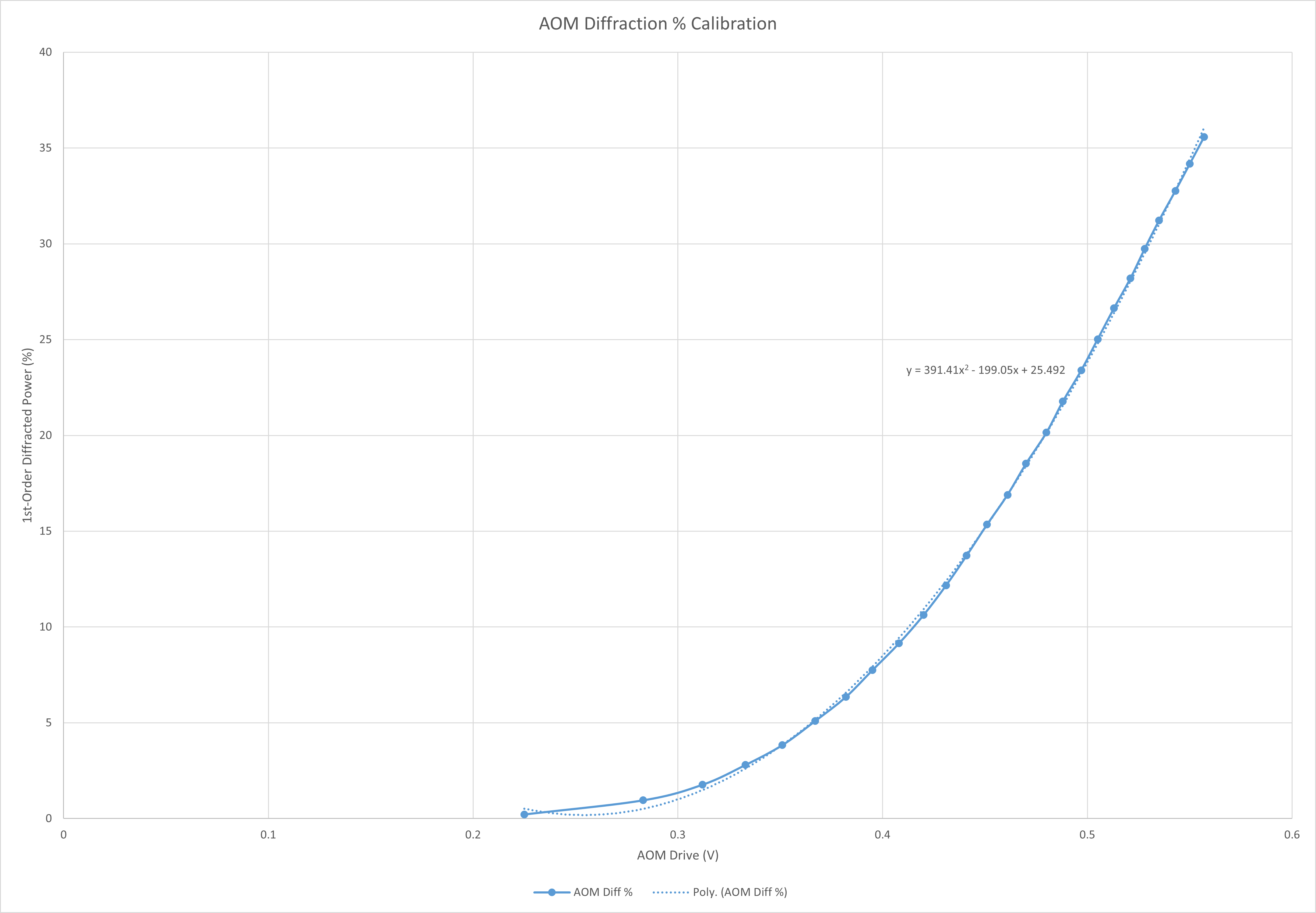
We started by measuring the amount of power in the diffracted beam with the ISS OFF, so it should be ~3% of our maximum power. We expected ~4.1W but measured 4.8W, so not quite right on the diffracted power % calibration. The ISS AOM alignment was tweaked to max the power in the diffracted beam; this was 6.4W. So we set about collecting the data needed to recalibrate the diffracted power % (change the Offset slider from 0 to 25 in steps of 1, recording the AOM voltage and power in the diffracted beam along the way). The power into the ISS AOM was measured at ~135.5W. To calibrate the diffracted power % we use the ISS AOM power in and the measured diffracted power to calculate the percentage of the PSL beam diffracted by the AOM, plot the AOM voltage vs this percentage, and fit a 2nd order polynomial to the resulting plot. The plot is attached and the new polynomial is: 391.4x2 - 199.05x + 25.492. We then set the Offset slider so that we had a "bank" of ~3% of our total Amp2 output for the ISS to use; the new Offset is 3.3, which gives us ~4.1W in the diffracted beam by default. We looked at our overnight trends of Amp2 output and saw a total drift of ~1.5% of the laser power, so we set the ISS bank to be double that; if we find we need more power in the band the Offset can be changed. We then adjusted the voltage on the ISS PDs to be near to 10V; PDA was reading 9.95V and PDB was reading 9.97V (PDB is currently our in-loop sensor and PDA is our out-of-loop sensor). To finish, we tweaked the ISS QPD alignment. Done with the ISS, we moved on to the FSS.
FSS
We started by trying to lock the FSS RefCav, and it locked on its own with zero issues. The TPD was reading 0.88V so we did nothing to the FSS. Should we need to tweak things up at a later date we will, but for now all appears healthy.
At this point we cleaned up the work space in the PSL enclosure and left, putting the enclosure into Science Mode once we had left. On the outside we measured TFs for the PMC, ISS, and FSS, as well as took a look at the FSS crossover.
Transfer Functions
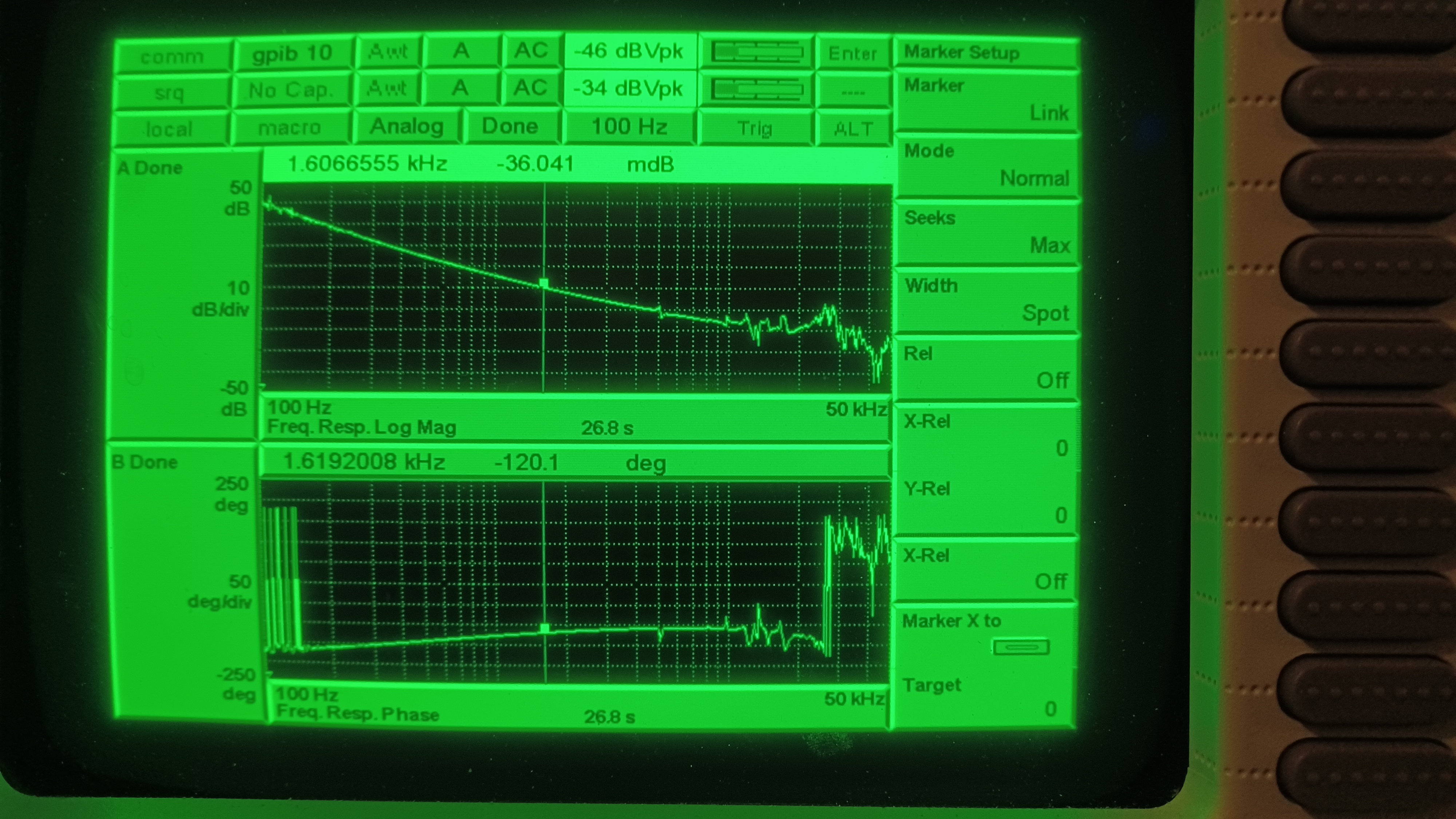
We started with the PMC. We measured the UGF at ~1.6kHz with a phase margin of 59.9 degrees, see 2nd attachment.
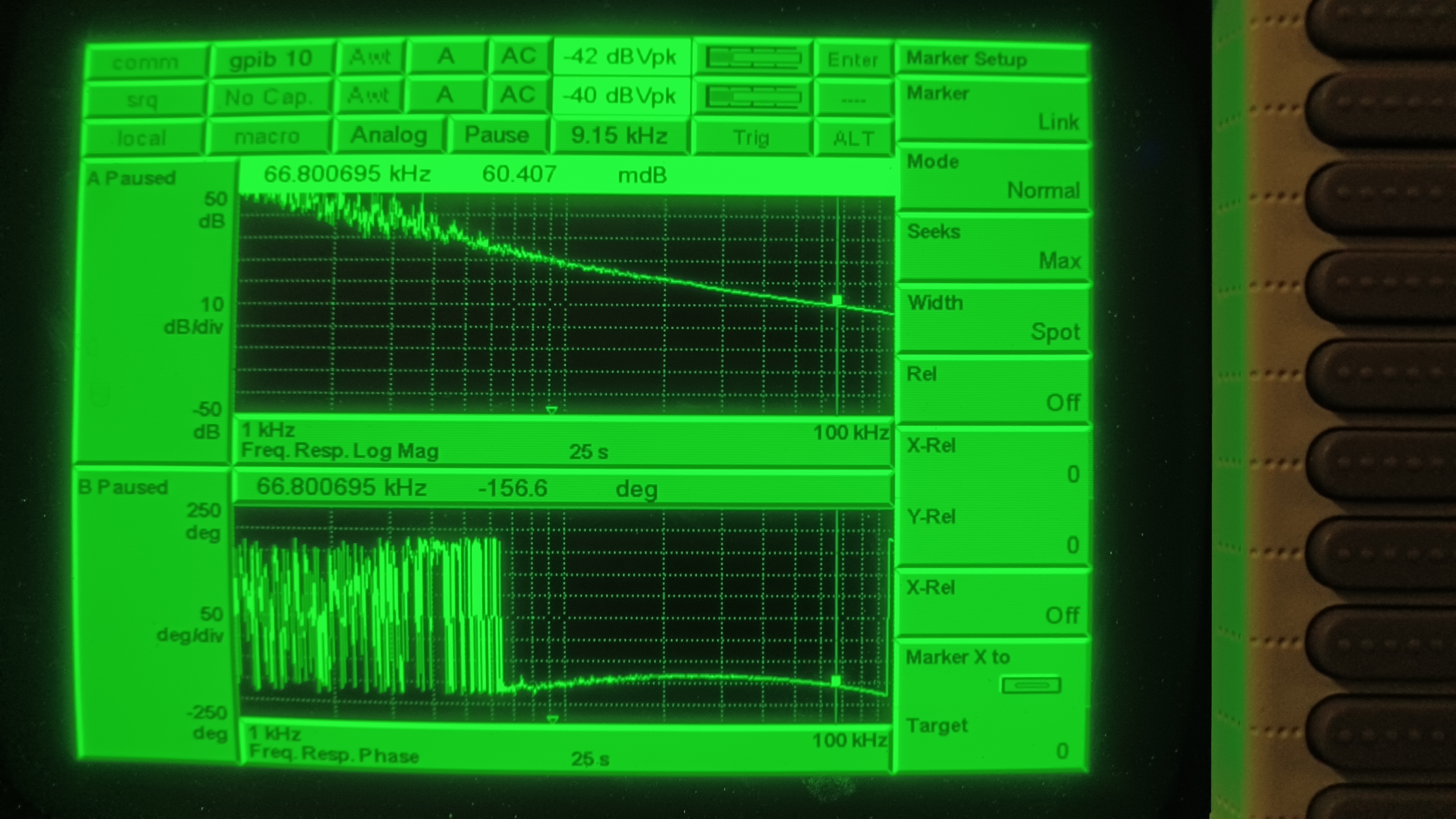
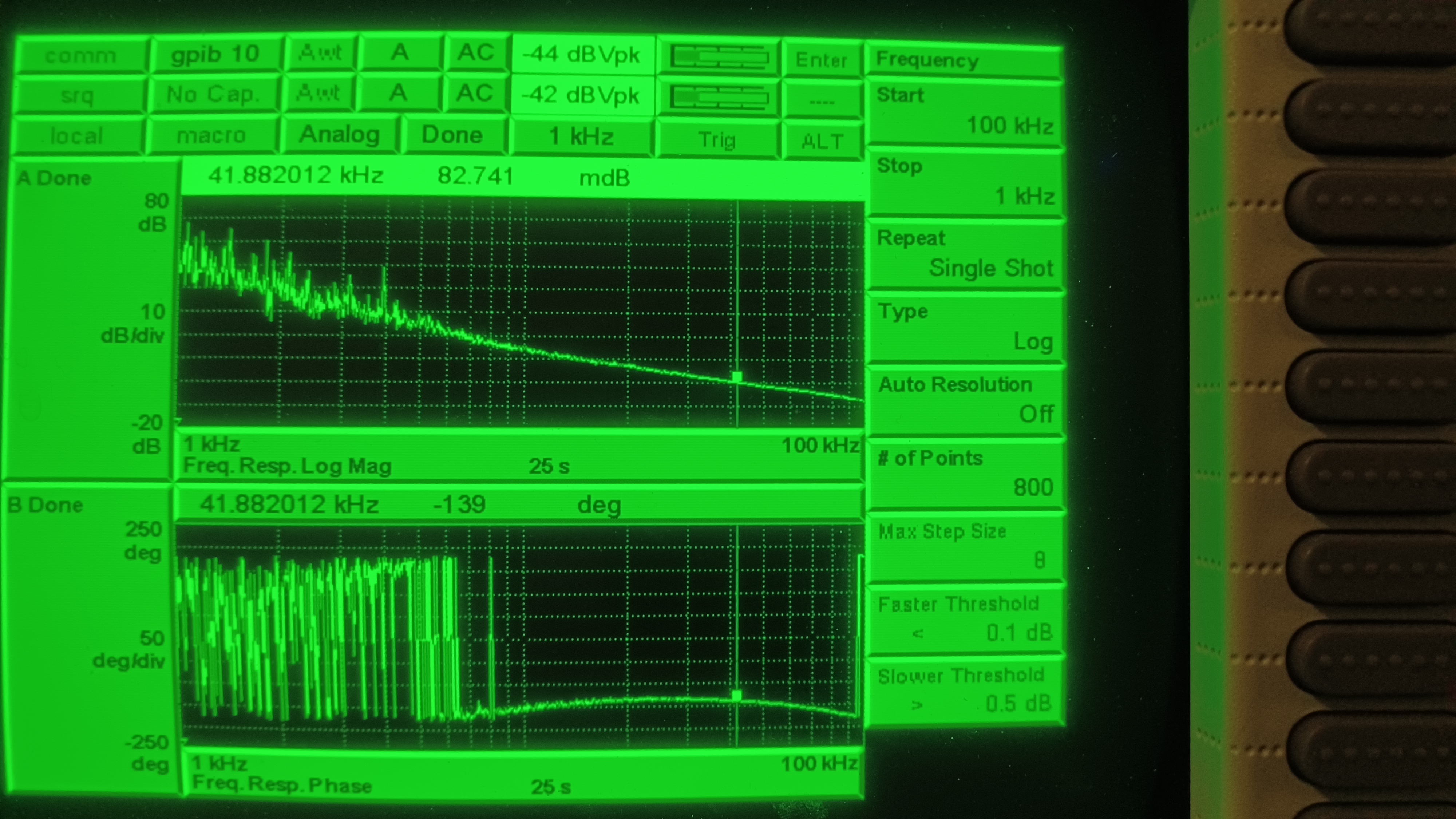
Next was the ISS. We measured the UGF at ~66.8kHz with a phase margin of 23.4 degrees, see 3rd attachment. This was much higher than we had measured in right before the NPRO swap, so we dropped the inner loop ISS gain by 4dB (from 11dB to 7dB). This put the UGF at ~41.9kHz with a phase margin of 41 degrees, much closer to where we were at before the NPRO swap (see 4th attachment).
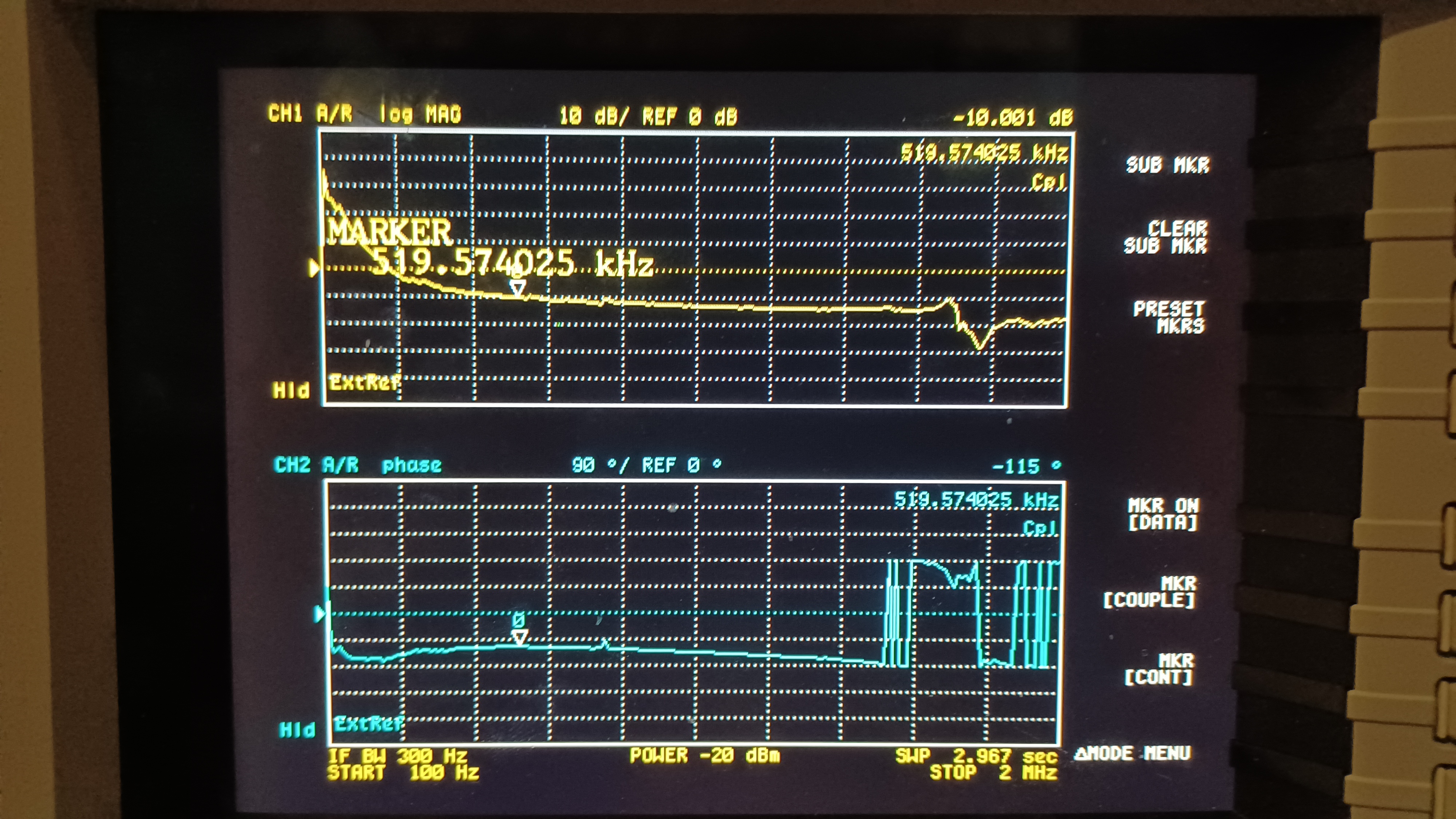
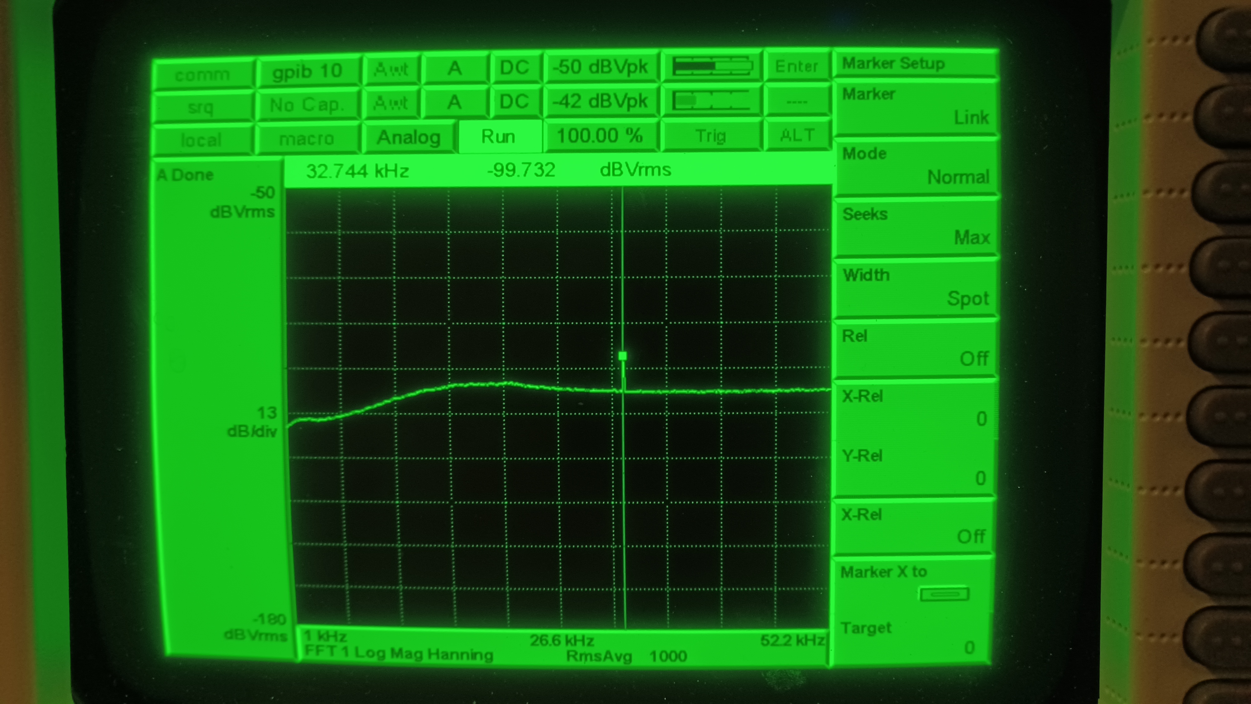
Finally, the FSS. We found the UGF around 420kHz, so we raised the Common Gain to 16dB (a change of 1dB) to put the UGF at ~519kHz with a phase margin of 65 degrees (see 5th attachment). We then looked at the NPRO PZT/PSL EOM crossover (take a spectrum of the IN1 port on the TTFSS box). We ended up lowering the Fast Gain from 7dB to 5dB to even out the crossover hump at ~20kHz, see final attachment. We did notice a new peak at ~32.7kHz that could be the PZT resonance of the new NPRO. We left this as-is for now, but if this becomes a problem we can tune the notch for the NPRO PZT to hopefully squash this peak; if that doesn't work we would have to pull the TTFSS and install a new notch. This finished LVEA work so we went to the Control Room.
Control Room
Back in the Control Room Ryan did a remote alignment of the PMC and FSS RefCav. Not much improvement on the RefCav, still have a TPD of ~0.88V with the IMC unlocked, but there was a good improvement in PMC Trans; the PMC is transmitting ~109.2W now. We also updated the diffracted power % calibration and set the ISS AOM to diffract ~3% (tagging OpsInfo, this should be around 3% now). We noticed the ISS AOM appears to be working harder with this NPRO, as the diffracted power % is moving more than with the previous NPRO. We'll keep an eye on this over the coming days.
DIAG_MAIN was also complaining about the NPRO noise eater being out of range. Looking at the channel it appeared the noise eater was off, even though we had it set in the PSL Beckhoff software to ON. Toggling the software switch did not change anything, so I went out to the LVEA and physically switched the noise eater ON (it should be OFF at the power supply for the software switch to work). This fixed the problem, so it appears there's something still not quite right with the remote diagnostics board in this NPRO, specifically with the remote noise eater switch. So for future info, if we have to toggle the NPRO noise eater it has to be done at the NPRO power supply in the LVEA, not in the PSL Beckhoff software.
We went through and accepted all of the SDF diffs from the NPRO swap, and Ryan did a rotation stage calibration (he'll post these results as a comment). At this point the NPRO swap was complete and the PSL is recovered and delivering light to the IFO again. At the time of writing the IFO is locked at Nominal Low Noise and Observing once again. This closes WP 12155.
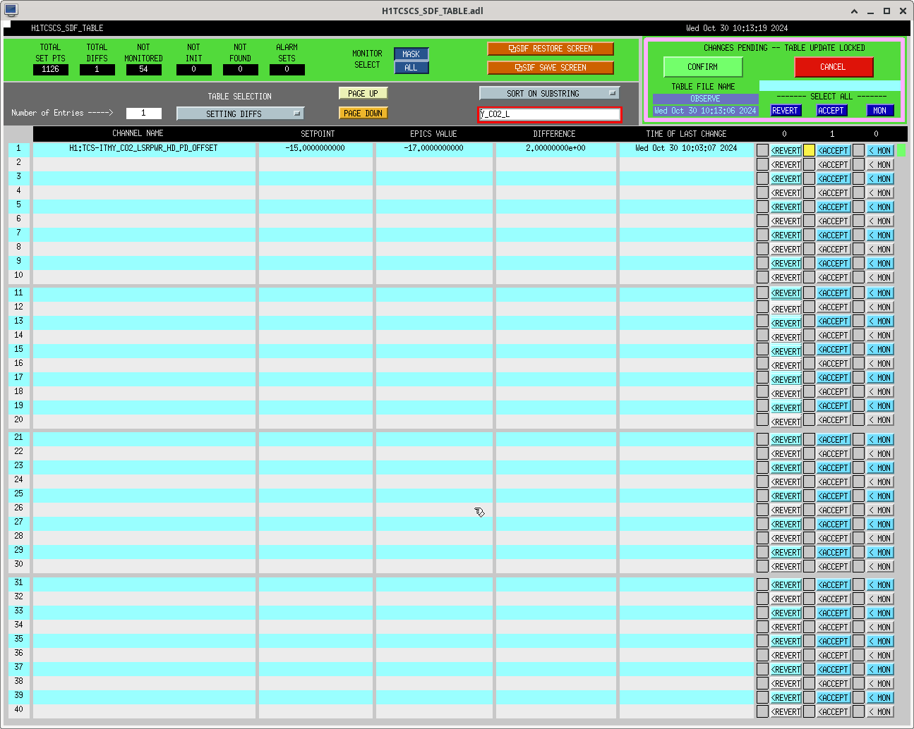
Reverted TCSY power head offset, was set to -17 reverted back to -15.
Reverted the channels in the screenshot related to ITMY HWS. I'm not entirely sure what these should be, but reverted for now should work until I can look into them further tomorrow.
I also added the TEST_NOTIFY node to the IFO node's exclude list. This wasn't an issue before because we have to specifically tell this node to check for new nodes, but we did a h1guardian1 reboot last week that pulled this node in.
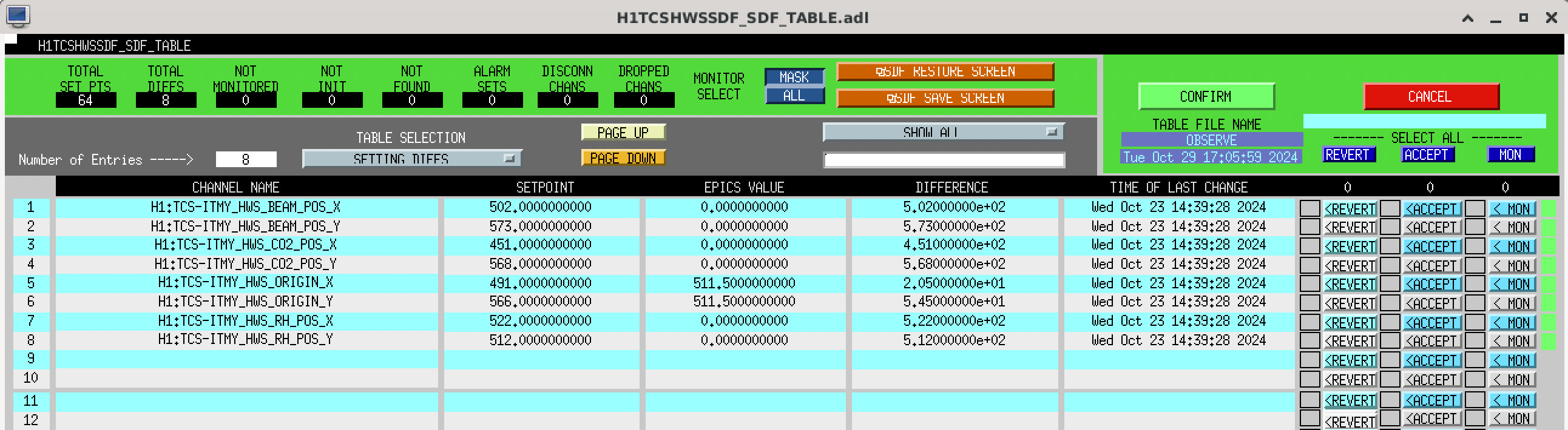
The HWS_ORGIN_X/Y channels are used in the HWS spherical power calculation and should be centered on the IFO beam, checked in 80148. The other HWS_BEAM/CO2/RH_POS channels aren't used for anything currently, but we had ideas of using them to monitor the location of the center of the RH, IFO beam and CO2 beam. They probably got reset tot he default values when the ITMY HWS computer crashed and IOC was restarted 80841. For all of these, reverting was correct.
Changed the LASER POWER head offset when we re-calibrated it in 80812. It's such a small number that it doesn't really matter but reverted to old setpoint. Was accepted in safe, now accepted in observe too sdf.
TITLE: 10/29 Day Shift: 1430-2330 UTC (0730-1630 PST), all times posted in UTC
STATE of H1: Corrective Maintenance
INCOMING OPERATOR: Ibrahim
SHIFT SUMMARY: Currently trying to relock and at PRMI after a productive maintenance day and finishing up of PSL work.
LOG:
22:48 Started manual initial alignment
22:59 Manual initial alignment done, relocking
| Start Time | System | Name | Location | Lazer_Haz | Task | Time End |
|---|---|---|---|---|---|---|
| 14:56 | FAC | Karen | OPTLab/VacPrep | n | Tech clean | 15:08 |
| 14:56 | FAC | Kim | EX | n | Tech clean | 16:40 |
| 15:09 | FAC | Karen | LVEA | n | Restocking supplies | 15:31 |
| 15:09 | FAC | Chris | Mid-/End-Stations | n | FAMIS tasks | 17:09 |
| 15:19 | HWS | TJ, Camilla | EX | n | HWS collimater swap | 16:43 |
| 15:32 | FAC | Karen | EY | n | Tech clean | 16:54 |
| 15:37 | Christina | OSB Receiving | n | Moving equipment | 16:30 | |
| 15:47 | FAC | Nelly | HAM Shack | n | Tech clean | 16:36 |
| 15:52 | Tour | Jackie | MechRoom, LVEA | n | Tour | 16:51 |
| 15:55 | PSL | RyanS, Jason | PSL Encl | y(local) | PSL work | 20:15 |
| 16:27 | Mitchell | LVEA | n | Checking stuff visually | 18:02 | |
| 16:45 | VAC | Gerardo | FCES | n | Vac work | 17:57 |
| 17:16 | TJ | LVEA | n | Looking for screws | 17:24 | |
| 17:32 | FAC | Kim | LVEA | n | Tech clean | 18:39 |
| 17:34 | FAC | Karen | LVEA | n | Tech clean | 18:32 |
| 17:39 | FAC | Chris | LVEA | n | FAMIS | 18:34 |
| 18:15 | TCS | TJ | LVEA | n | Moving old CO2Y laser | 18:25 |
| 18:29 | - | TJ | LVEA | n | Sweep | 18:51 |
| 18:34 | FAC | Chris | n | Moving Forklift WT -> VPW -> Staging | 19:21 | |
| 19:01 | VAC | Gerardo, Jordan | EX | n | Vacuum things | 19:31 |
| 19:03 | 3IFO | Tyler | LVEA | n | 3IFO checks | 19:10 |
| 20:53 | Laser | Vicky, Daniel | LVEA, EX, EY | n | Adjusting temperature offsets for ALS, SQZ lasers | 21:45 |
| 21:11 | FIT | Francisco, Neil | EY | n | Running very far | 22:01 |
| 22:14 | PSL | Jason | LVEA | n | Switch NoiseEater switch | 22:21 |
| 23:05 | Vicky, Oli | LVEA, CER | n | Turn lights off/put laptops back | 23:10 |
TITLE: 10/29 Eve Shift: 2330-0500 UTC (1630-2200 PST), all times posted in UTC
STATE of H1: Corrective Maintenance
OUTGOING OPERATOR: Oli
CURRENT ENVIRONMENT:
SEI_ENV state: CALM
Wind: 14mph Gusts, 9mph 3min avg
Primary useism: 0.02 μm/s
Secondary useism: 0.23 μm/s
QUICK SUMMARY:
IFO is LOCKING at PRMI
PSL Maintenance was ongoing throughout the day with PSL work finished (for now).
We've gone through a manual initial alignment and are now locking, which is apparently optimistic.
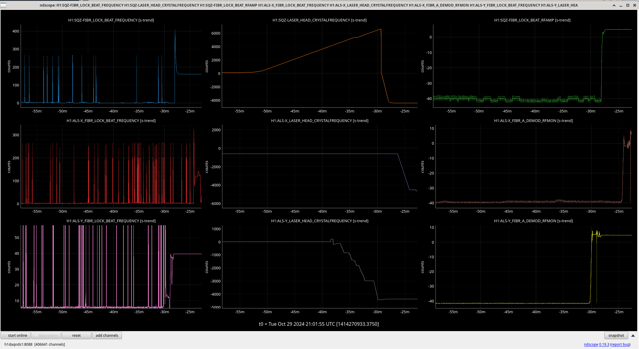
Daniel noted that the new NPRO is almost certainly at a different frequency than the previous one. Also, since the PSL has been the most 'fussy' lately, we don't want to change it away from it's manufacturer-recommended settings (if we can help it), and instead want to change the other 3 lasers to match the new PSL frequency.
In the attachment, the top row is SQZ laser, the middle row is ALSX, and the bottom row is ALSY. The leftmost column is the beatnote frequency between the given laser and the PSL, the middle column is the CrystalFrequency offset that we can provide, and the right column is the amplitude of the RF beatnote.
To figure out "where to go", Daniel put in a set of steps (eg, using ezcastep) to the CrystalFrequency channels. You can see that he started with the SQZ laser, but wasn't finding it by using a positive frequency offset. He then found (using ALSY) that putting in a negative frequency offset of a little over 4 GHz (the CrystalFrequency numerical value is in units of MHz) brought the RFMON up, and the PLL loop was able to engage and bring the beat frequency to the right spot. Once the RF mon started increasing, he Ctrl-C'd to stop the stepping of values. Knowing that all 3 of these aux lasers at one point were matched to the PSL, he then set the SQZ laser and the ALSX laser to search around that -4 GHz value. In order to have the PLL loops engage and not complain, Daniel set the H1:ALS-X_FIBR_LOCK_TEMPERATURECONTROLS_HIGH and _LOW settings for all 3 lasers to be a wide acceptable window (eg, +/- 6000 MHz, rather than a normal +/- 600 MHz).
Once all 3 lasers had their PLLs locked, Daniel and Vicky went out to each laser to adjust the nominal temp such that the CrystalFreq offset can be closer to zero. My understanding of the procedure is that they will (with the PLL locked using the big offset) take a look at the current temp of the laser, according to the little LCD display on the front panel of the laser controller. They will unlock the PLL and set the CrystalFrequency offset to 0, and then adjust the analog knob on the laser controller such that the temperature is back at the temp it was with the PLL locked with big offset. They'll then allow the PLL to relock, hopefully not needing a very big CrystalFrequency offset. While at each laser, they will also check that the laser is not in a mode hopping region with this new temperature.
After this is done, and once the PSL tune-ups are done for the day, we'll be able to start locking!
Daniel, Vicky - adjusted temperatures on the ALS and SQZ lasers: 1) Noted the laser temp when TTFSS was running (> 4GHz off). This is the "nominal" new temperature. 2) Turned off TTFSS and set crystal frequency to 0 MHz. 3) Moved laser temperature knob to bring it to the "nominal" temperature. 4) Check TTFSS locks well. If needed, further adjust laser temperature knob to bring the crystal frequency is 0 MHz when TTFSS is running. 5) Check for mode-hopping.
To check for mode-hopping with laser temperature on the controller set at the new nominal, we turned off TTFSS and stepped the laser frequency +/- 200 (SQZ) or +/- 100 (ALS X/Y) MHz, then checked the beat note strength and frequencies made sense. All looked good at the new nominal laser temps. To make up the ~4 GHz laser frequency difference, we expected to change temperatures by like (-4.4 GHz / -3000 MHz/V) ~1.47 C, which is similar to what we did.
Laser temps changed as follows:
After the SQZ laser temperature was changed by ~4.4 GHz to meet the new PSL laser frequency, we had to change the OPO TEC temperature setpoint from 31.207 C --> 31.477 C. This is a bigger change than usual, but we had to adjust the temp to find and lock the OPO in dual-resonance (at first, there was almost no CLF6 beatnote, started out with RFMON around -40 when it should be around -11. By contrast the OPO locked fine yesterday).
At 31.477 C, we used the temperature to maximize NLG with seed light: amplified=0.133, de-amplified=0.0027, un-amplified=0.0087. NLG = amplified /unamplified ~ 15.25. Then H1:SQZ-CLF_REFL_RF6_DEMOD_RFMON = -10.9.
I preemptively swept the LVEA since it seems like the PSL work will complete soon. The only things of note are I ended up unplugging 5 unused extension chords.
The last remaining items are: PSL in Science mode, wifi off, LVEA lights off, PSL phone unplugged in 163.
The remaining checks from the LVEA sweep have been done.
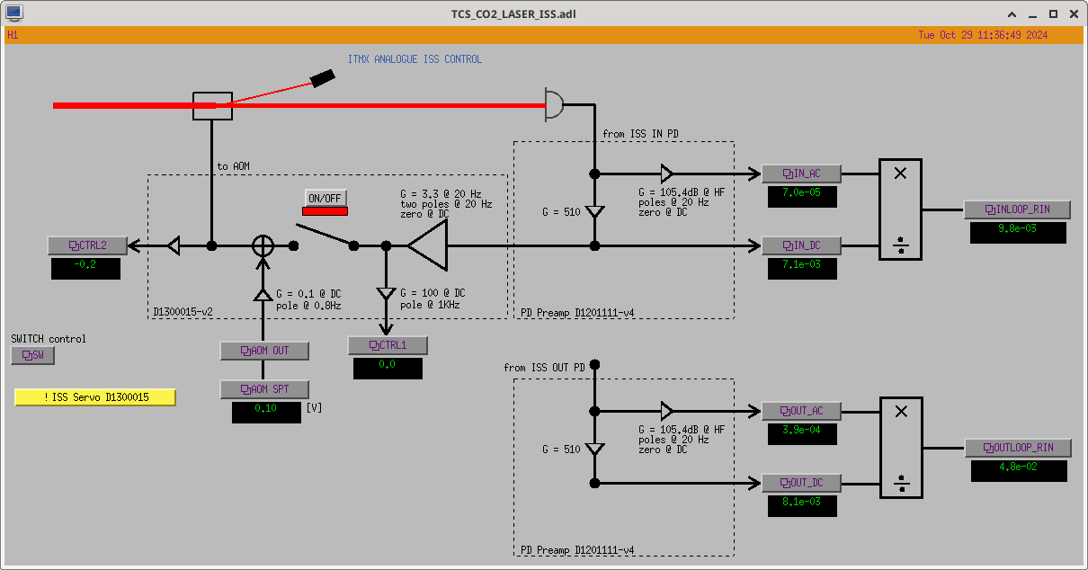
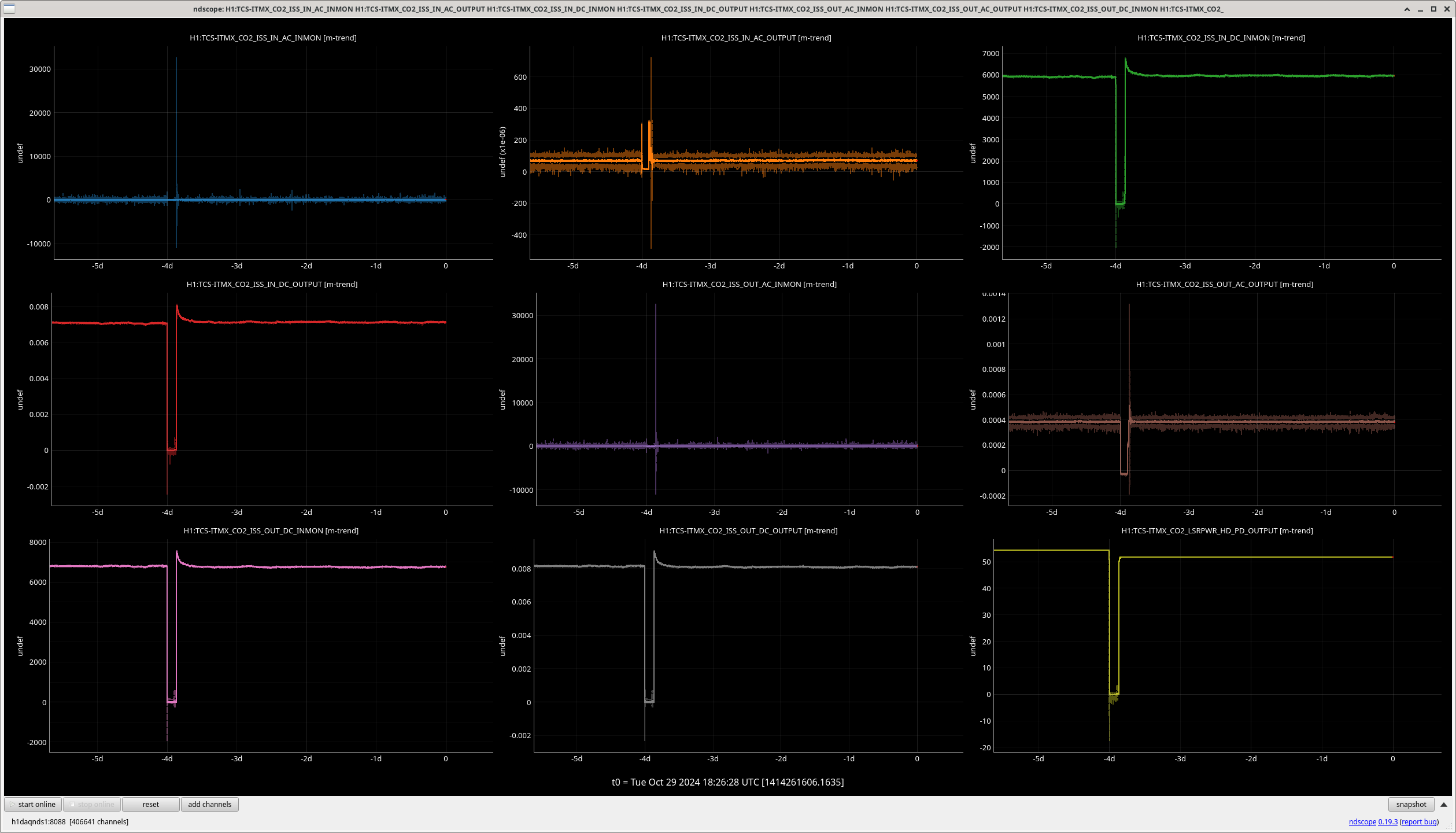
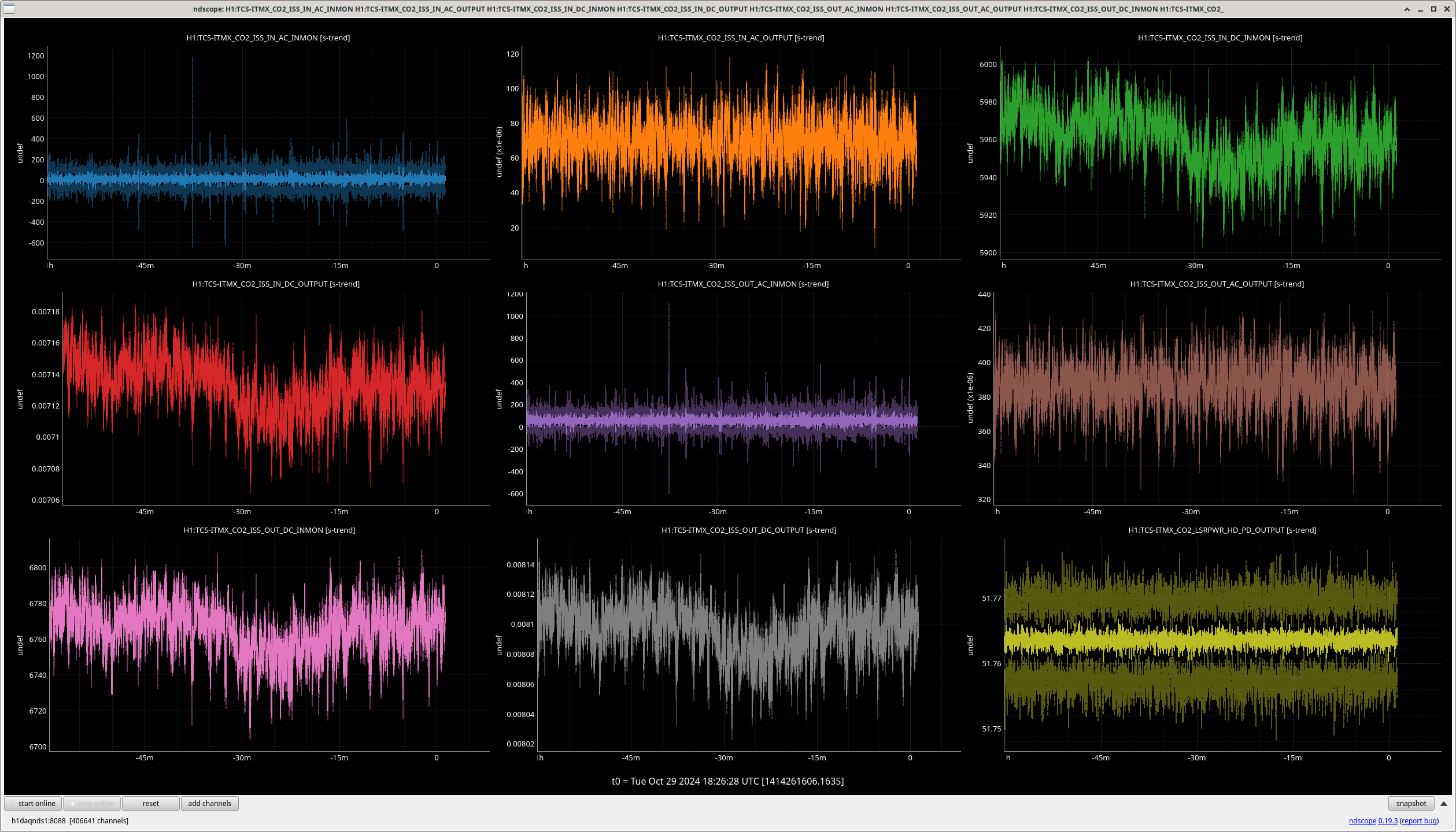
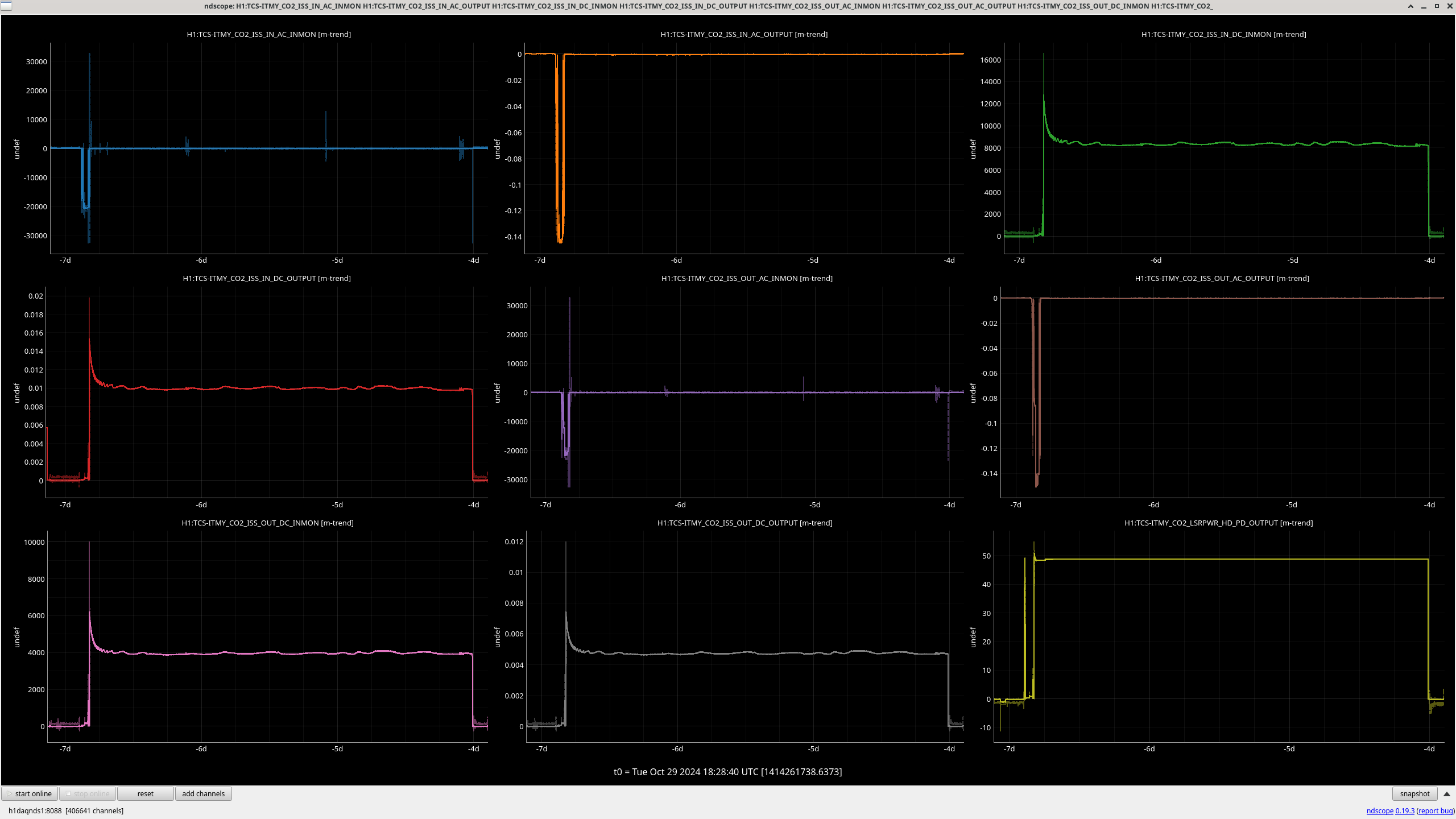
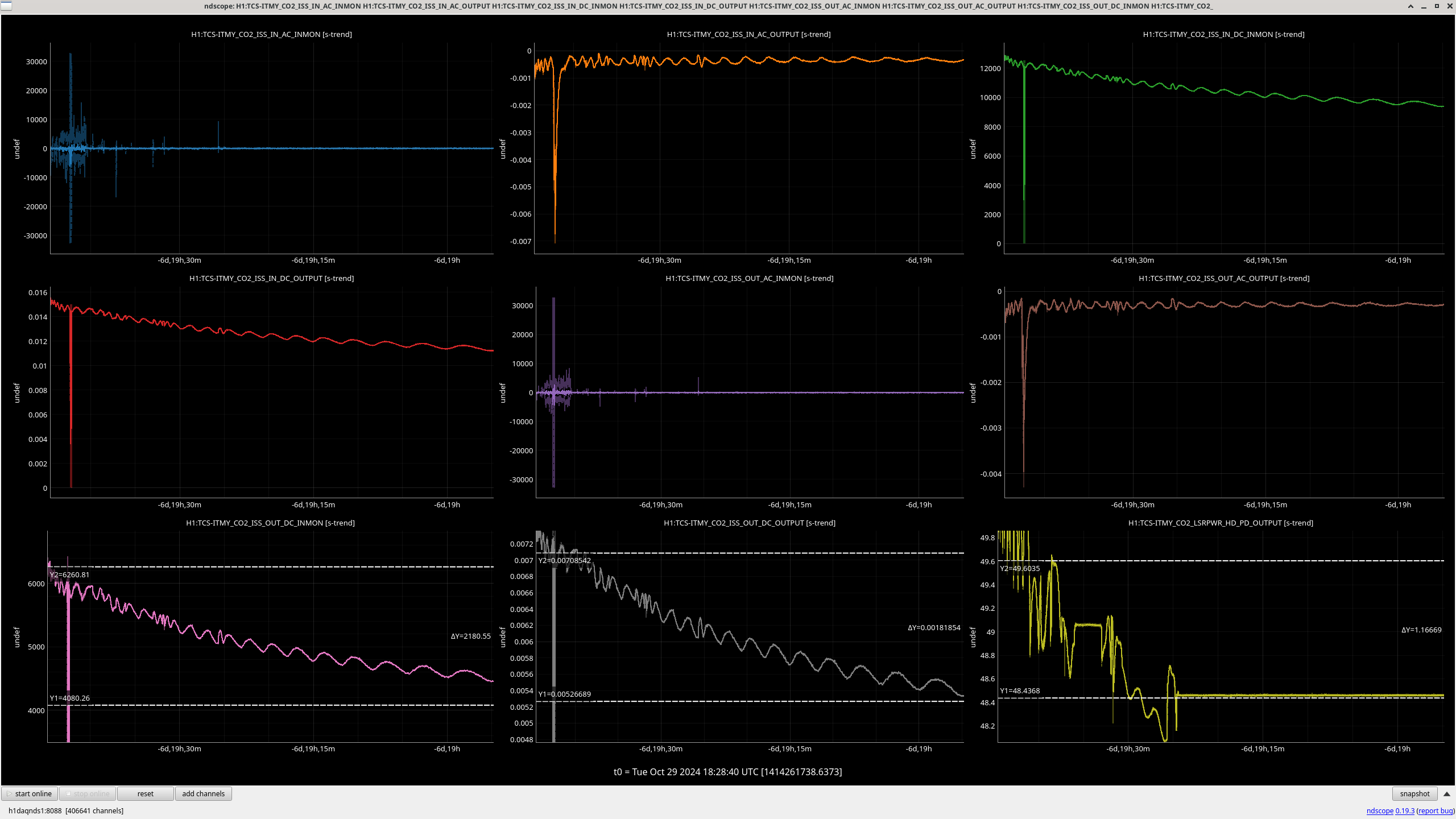
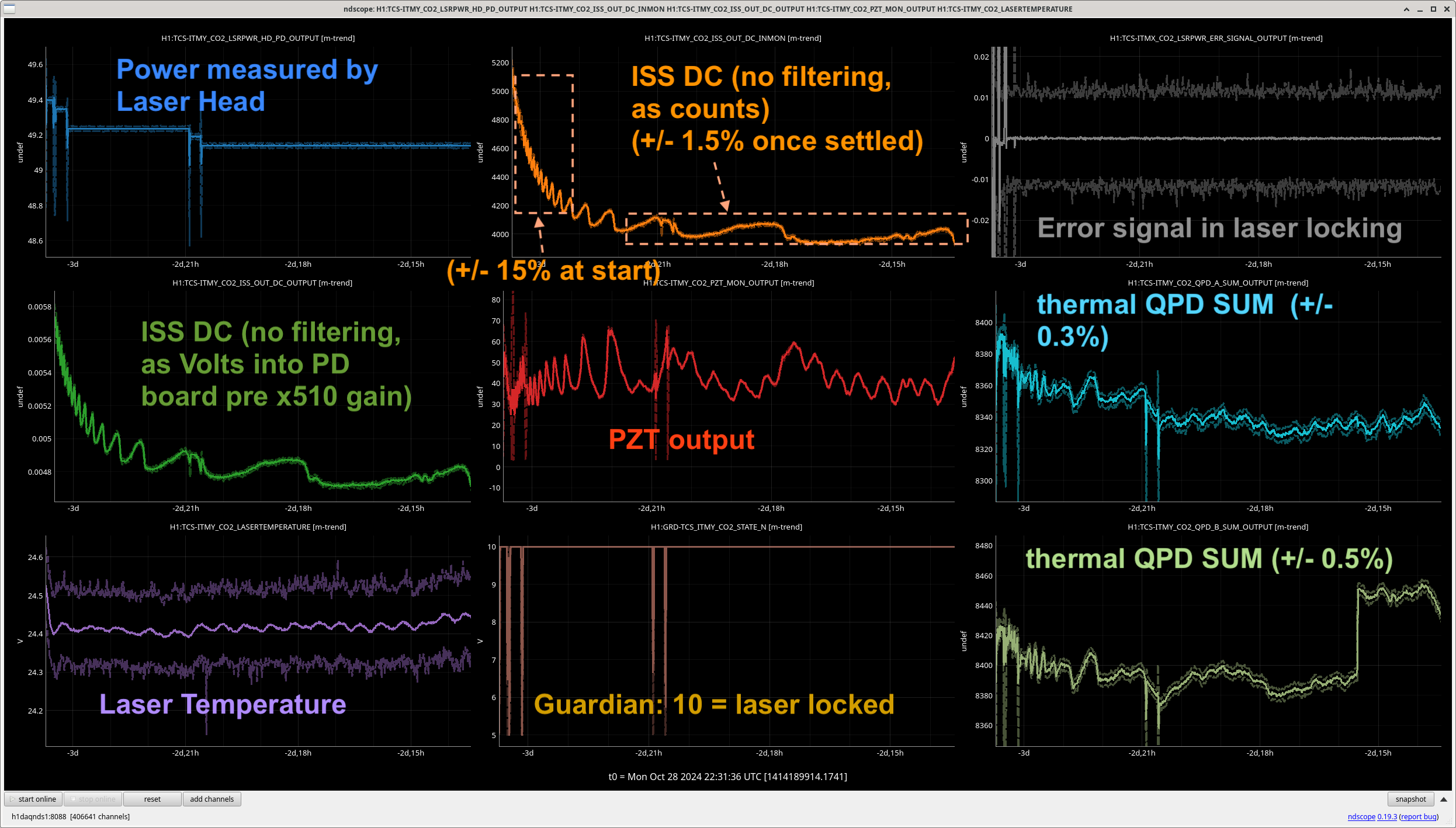
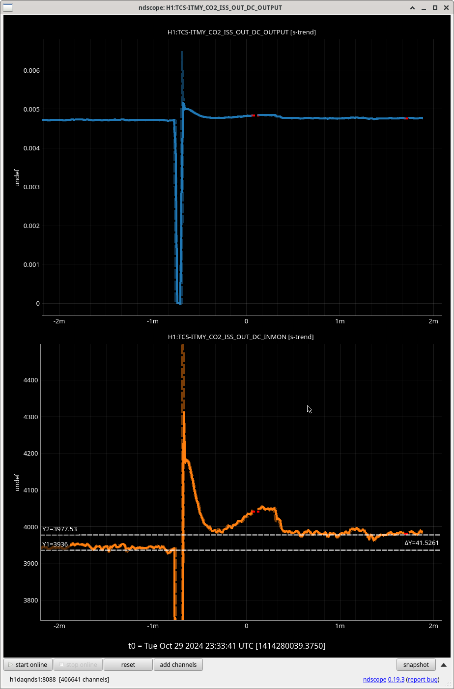
Looking at the CO2 ISS PD trends (qty 2 on each table labeled IN and OUT of loop), as the CIT CHETA setup that uses this PD is still getting confusing results (e.g. CIT#481). Each PD as an AC and DC mon output, from the DB9 of the PD preamp board D1201111.
Inially the DC signals look as expected, dropping to zero when laser is off (CO2X plot / CO2Y plot). CO2X stays within 1% when the laser is stable (CO2X plot). Though the CO2Y plots looks worse, only staying within 5% when the laser is stable (CO2Y plot).
If you pay attention to the ~hour region once the laser is first turned on in both lasers (worse in CO2Y, see plot) the ISS PDs show power signal varying much more than the CO2 power head PD does. I don't understand why that would be, but this could explain the issues we've seen at CIT where the laser is always ina less stable state as is fan cooled rather than water cooled.
CO2Y_IN shipped to CIT in 80883.
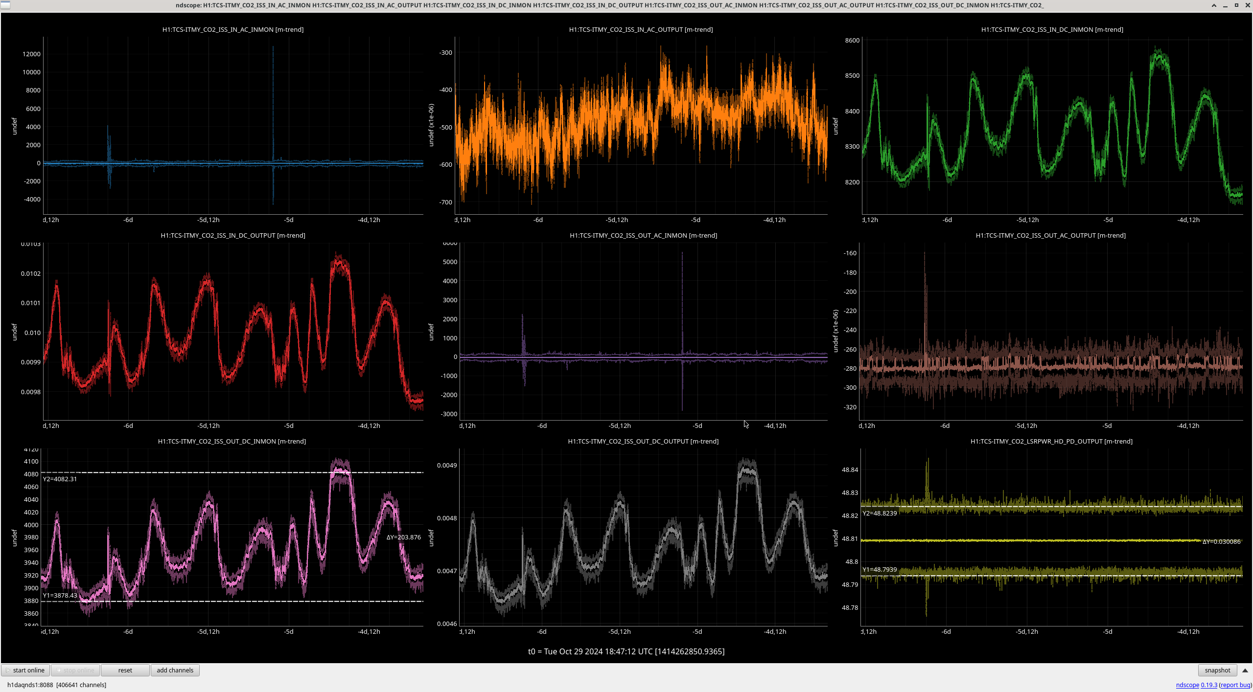
After suggestion from Keita, I have added trends of the thermal QPD NSUMs, which also shows this 9 minute oscillation but on a much smaller scale (less than 1% wobble). Plot here
The laser head reported power is in-loop (i.e. it's output is stabilized via the laser PZT), So it makes sense that it's very flat. There seems to be not much in this feedback loop, as laser power set point a PZT set point and a 0.5Hz integrator. Also the signal seems to go straight to the chiller with a ~1 hour integrator, I'm not sure if this really makes sense, but it seems to work.
I'm still unsure why the ISS QPDs see such a big change at the start of turn on. To check if the PDs or Laser warming up cause this, I turned the CO2Y laser off then quickly (~5 seconds) on again. This seemed to decrease the time of wobbles, plot attached.
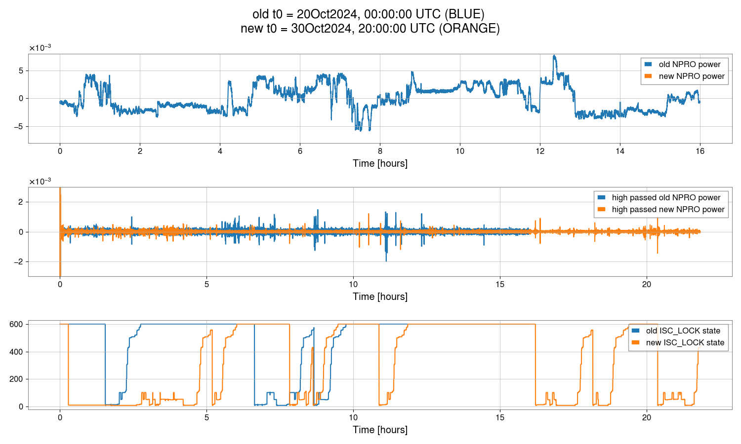
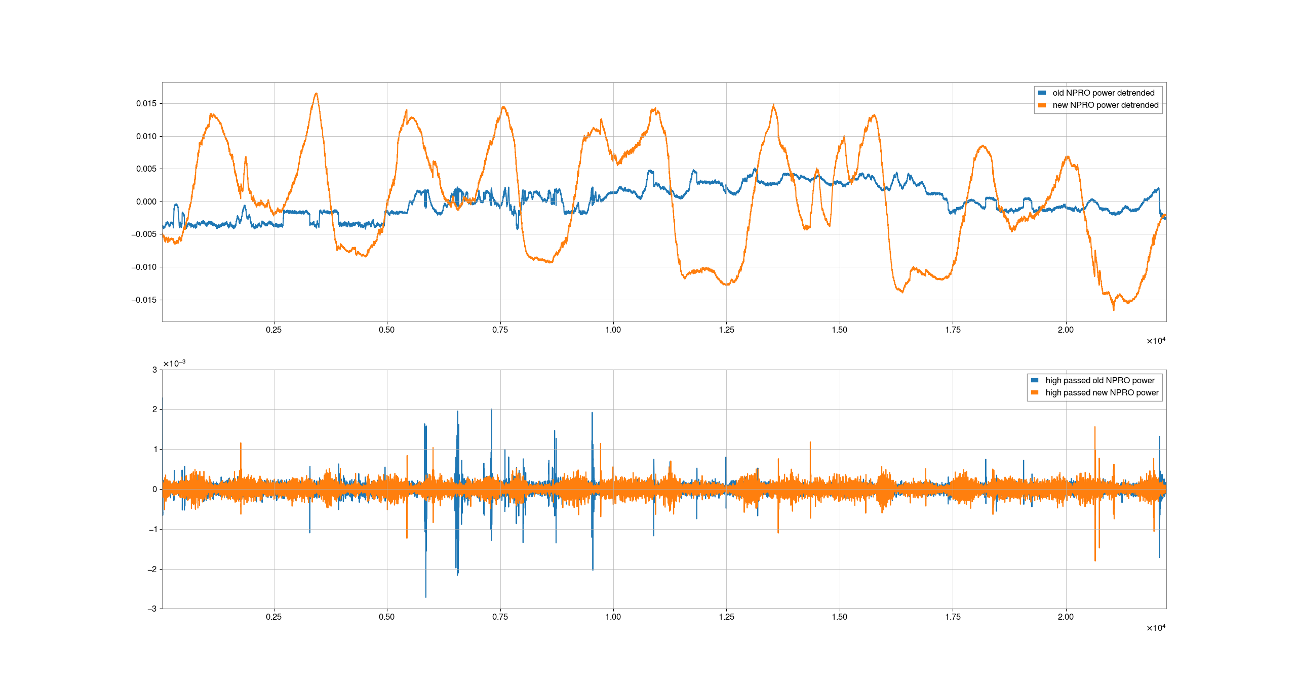
Continuing on from Jenne's observation that there are still glitches in the new NPRO, I've tried to make a plot we can use to compare the glitch rate in the new and old NPROs, using the NPRO_PWR channel instead of the FSS channel which isn't available for the new NPRO.
I've used a 3 hour stretch of observing time for the old NPRO, and a three hour stretch before the time when Jenne made a plot in 80837. The ISS is not on for the new NPRO time, which is probably why the intensity is flcutuating and making it harder to see the small steps in power that are the glitches we are looking for. In the second panel, I've plotted the data high passed with a 0.05 Hz butterworth, this helps to show the glitches, although not perfectly (in either case). Based on this, the glitches look to be happening at a roughly similar rate, although somewhat less with the new NPRO.
This script in in sheila.dwyer/DutyCycle)4/dutycycleplots/PSL_glitches.py
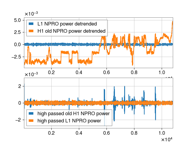
Attaching another plot, showing that comparing our old NPRO to LLO during an observing stretch that started at midnight UTC time on Oct7th, LLO has no similar glitches.
Here's the same plot, but using a time from last night when the PSL environmental controls were off. There are still gltiches, but fewer.
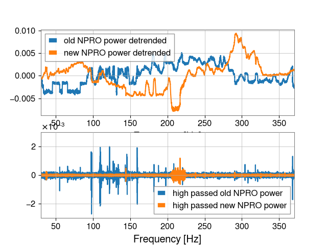
These plot tiles show runs of Sheila's code looking for PSL power glitches on several days before / after the suspect date around Sept 12.
There's not a clear correlation between the glitches and locklosses. While maybe there's more glitches after Sept 12 (bottom row), the glitches don't consistently correlate with locklosses? Sept 14 is a good example of this: lots of glitches, the IFO stays locked through many of them.
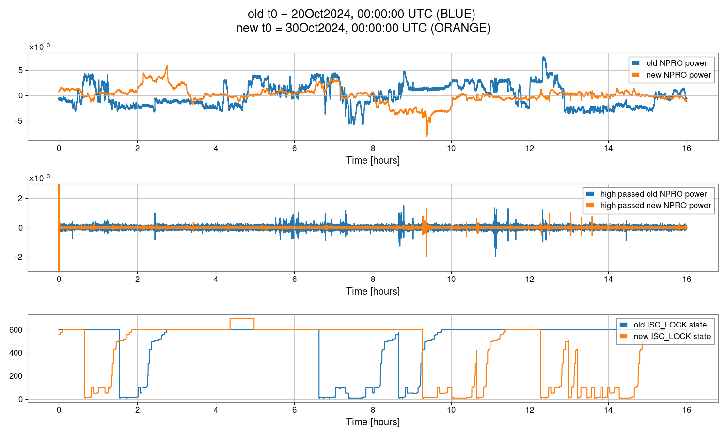
2nd plot here shows overnight again with the swapped new laser. There are still glitches (though potentially less).
The PSL-PWR_NPRO_OUT_DQ channel seems to not be connected at LLO, which explains why the comparison plot a few comments above makes it look like L1 PSL is so much quieter than H1.
Adding screenshot of the NPRO power glitches over the past day. There are still glitches with the new laser -- not all glitches correspond to locklosses, but some do.