Ibrahim, Betsy, Anamaria
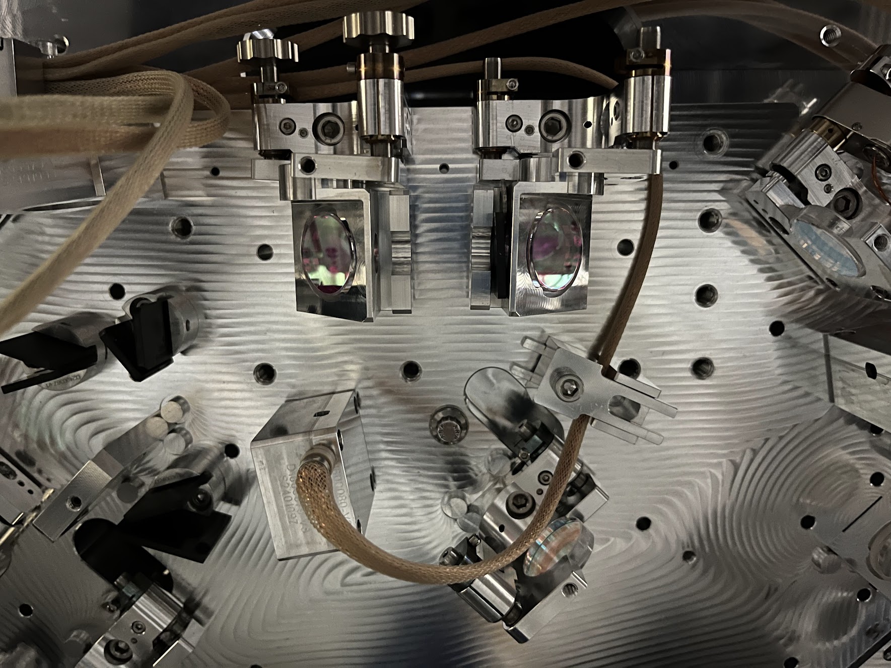
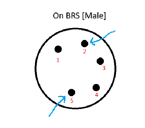
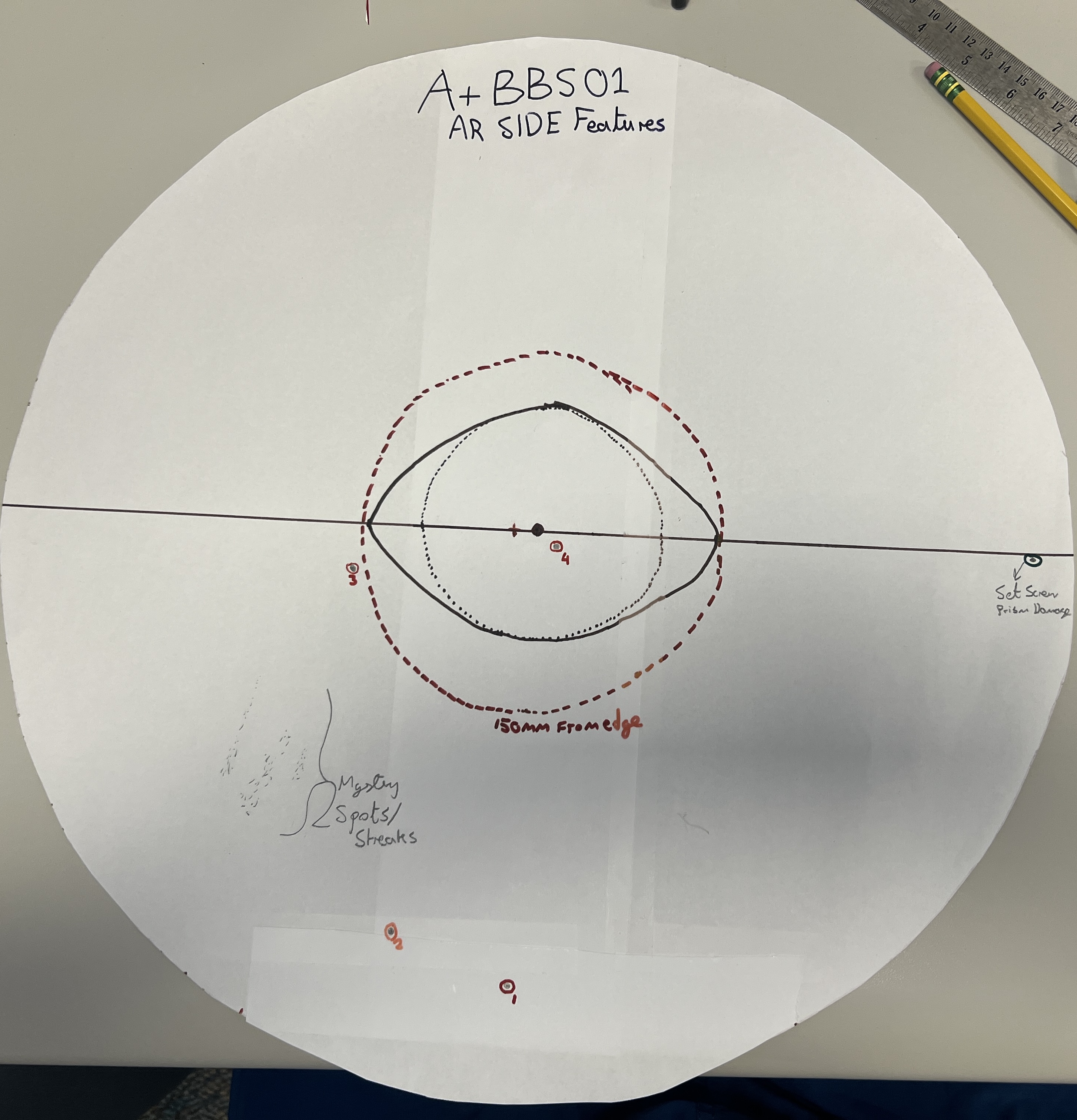
Upon first in-chamber BBS01 inspection, we found 3 large clumps of spots approximately 100mm from the edge. We're consulting GariLynn at CIT for steps on how to clean.
Acetone swab: We tried to go over the spots with a cotton swab with acetone, but the spots remained.
First contact: We then tried to first contact a small portion with one thin layer, but the spots remained.
While there's no evidence that the beamsplitter was contacted, dinked, touched or scratched in anyway, this might be a cause for the damage. There is texture to the spots upon brushing them with a swab and while it seems more likely that these are above the surface, we are not totally sure.
Hypotheses (and their problems)
1. Peek In-Vac cable scratch: maybe an in-vac cable fell on that area but they would have had to imprint multiple times with some force to show something like this.
2. Falling foil: maybe a piece of foil fell onto the surface and scratched it that way? No foil was used or wrapped at height during BBS and again, the foil would have had to fall with some heft.
3. There-the-whole-time: Maybe the spots were there the whole time and are invisible to non-chamber conditions. Because this is on the AR side, there is no good scatter plot of the surface. Since we did not see this in normal light conditions, but immediately saw this in chamber (dark) conditions, this may have been there all along. The spots are quite large (as attachments show), so this makes that less likely.
4. Dry first contact: Maybe it's dry first contact? We went over some of the spot with acetone but it stayed. We also first contacted a thin layer on one part but it stayed. The nature of the spots do look like they're small first contact bubbles. We found the first contact sheet that we used on that side and indeed, there are some similar streaks in size but nothing conclusive. We're looking at matching the spot with the first contact to see if there is a streak in this region. Problem is - first contact wouldve come off quick with the acetone treatment. So this is also not likely it.
What to do next:
- Analyze with Dino-Lite: We're going to zoom in on the spots with our DinoLite mount to get a better look. This could tell us if they are truly scratches or stuck particulate.
- Match first contact sheet with spots: Seeing if these spots were visible during FC (done on May 6) - alog 90149. Nothing visible.
- Anamaria suggested at any rate shining a gaussian beam at it to analyze the damage in a short experiment to characterize.


(Jordan V., Travis S., Gerardo M.)
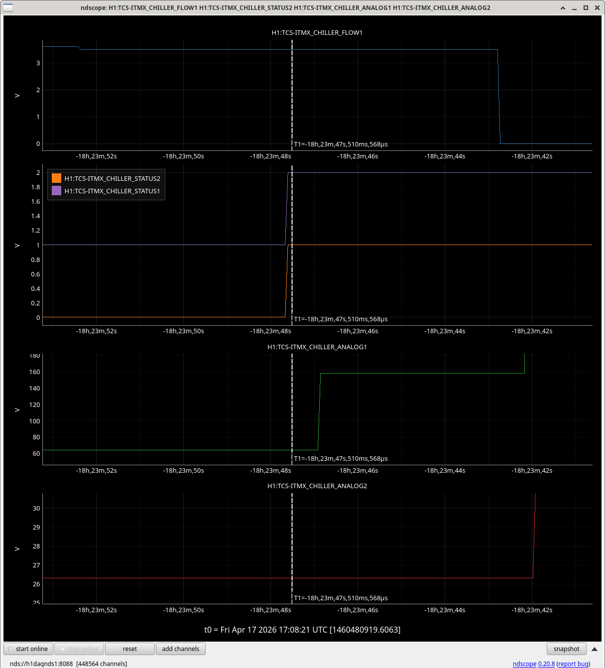
CP1 cooldown re-start, apparently one or both of the valves did not respond as they should have, either the "bottom draw" and the "bypass" valves did not open yesterday, or one of them did not open, do not know which.
This morning I opened the valves in a different manner, and paid close attention to their behavior, the "bottom draw" valve made a small pop as I opened it, so I closed the valve and then opened it again, I had to do that about 3 different times, the last time there was no pop, it seems as if the valve was letting go of the sealing component, on the third attempt I was able to hear the LN2 rush thru. Same for the "bypass" valve, opened it with care and paid attention to the sounds it made, no pops noted, but to make sure I opened and closed the valve 3 times, never opening it more than 1/2 turn. Then set it the same way as yesterday, the guestimate of 10% open, about 0.8 turns. Then I was able to hear the nitrogen gas out of the exhaust line. Left CP1 and went to check on the progress via MEDM screens and plots. Soon we had the first numbers on the pump level % full, we started with a very tiny number but little by little the cryotrap started to fill. Because of the experience of with the above mentioned valves I decided to actuate early the LLCV, but only opening it up to 2%, eventually with time and two cell phones I was able to note that the LLCV was indeed actuating good. Soon the 85% came along and it was time to hand over the controls to the PID, which it did not have any issues, well 1 issue, the 15% output low limit was to high, the PID railed, so I lowered it to 10%, this number will be assessed on the upcoming days to see if we leave it or not. We left the RGA scanning during and post the cryotrap cooldown.
Vacuum pressure in CP1 has dropped and currently we are at 3.8x10-09 Torr, from about 4.0x10-08 Torr this morning.
The consumption of LN2 was good, the dewar dropped about 2.24% to fill the cryotrap.
The turbo pump continues to pump on the system and it will until we reach at least 1.0x10-09 Torr or better.