Ran the usual broad band and simulines following the wiki. I ramped the AS_A Y offset to OFF before starting this measurement.
Simulines start:
PDT: 2024-09-19 08:37:18.910765 PDT
UTC: 2024-09-19 15:37:18.910765 UTC
GPS: 1410795456.910765
2024-09-19 15:37:20,007 | INFO | File written out to: /ligo/groups/cal/H1/measurements/DARMOLG_SS/DARMOLG_SS_20240919T1
53719Z.hdf5
2024-09-19 15:37:20,021 | INFO | File written out to: /ligo/groups/cal/H1/measurements/PCALY2DARM_SS/PCALY2DARM_SS_2024
0919T153719Z.hdf5
2024-09-19 15:37:20,035 | INFO | File written out to: /ligo/groups/cal/H1/measurements/SUSETMX_L1_SS/SUSETMX_L1_SS_2024
0919T153719Z.hdf5
2024-09-19 15:37:20,046 | INFO | File written out to: /ligo/groups/cal/H1/measurements/SUSETMX_L2_SS/SUSETMX_L2_SS_2024
0919T153719Z.hdf5
2024-09-19 15:37:20,056 | INFO | File written out to: /ligo/groups/cal/H1/measurements/SUSETMX_L3_SS/SUSETMX_L3_SS_2024
0919T153719Z.hdf5
End:
2024-09-19 16:06:55,132 | INFO | File written out to: /ligo/groups/cal/H1/measurements/DARMOLG_SS/DARMOLG_SS_20240919T1
53719Z.hdf5
2024-09-19 16:06:55,144 | INFO | File written out to: /ligo/groups/cal/H1/measurements/PCALY2DARM_SS/PCALY2DARM_SS_2024
0919T153719Z.hdf5
2024-09-19 16:06:55,155 | INFO | File written out to: /ligo/groups/cal/H1/measurements/SUSETMX_L1_SS/SUSETMX_L1_SS_2024
0919T153719Z.hdf5
2024-09-19 16:06:55,166 | INFO | File written out to: /ligo/groups/cal/H1/measurements/SUSETMX_L2_SS/SUSETMX_L2_SS_2024
0919T153719Z.hdf5
2024-09-19 16:06:55,176 | INFO | File written out to: /ligo/groups/cal/H1/measurements/SUSETMX_L3_SS/SUSETMX_L3_SS_2024
0919T153719Z.hdf5
ICE default IO error handler doing an exit(), pid = 1416632, errno = 32
PDT: 2024-09-19 09:06:55.226746 PDT
UTC: 2024-09-19 16:06:55.226746 UTC
GPS: 1410797233.226746
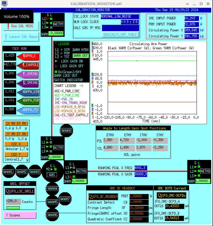
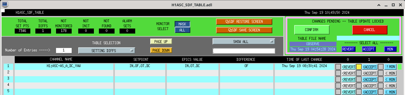
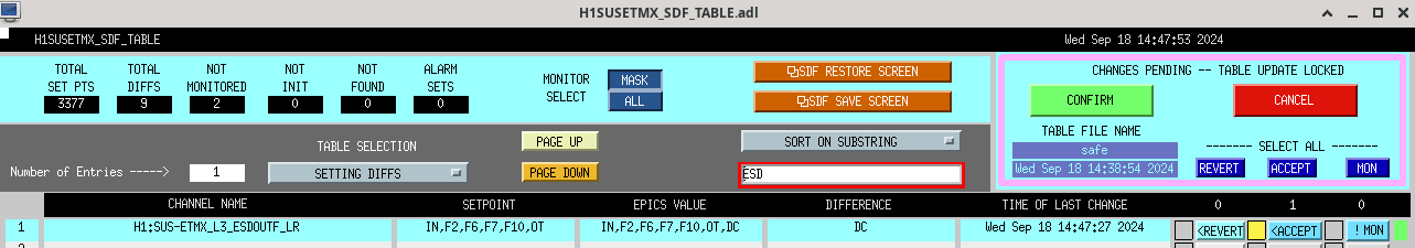
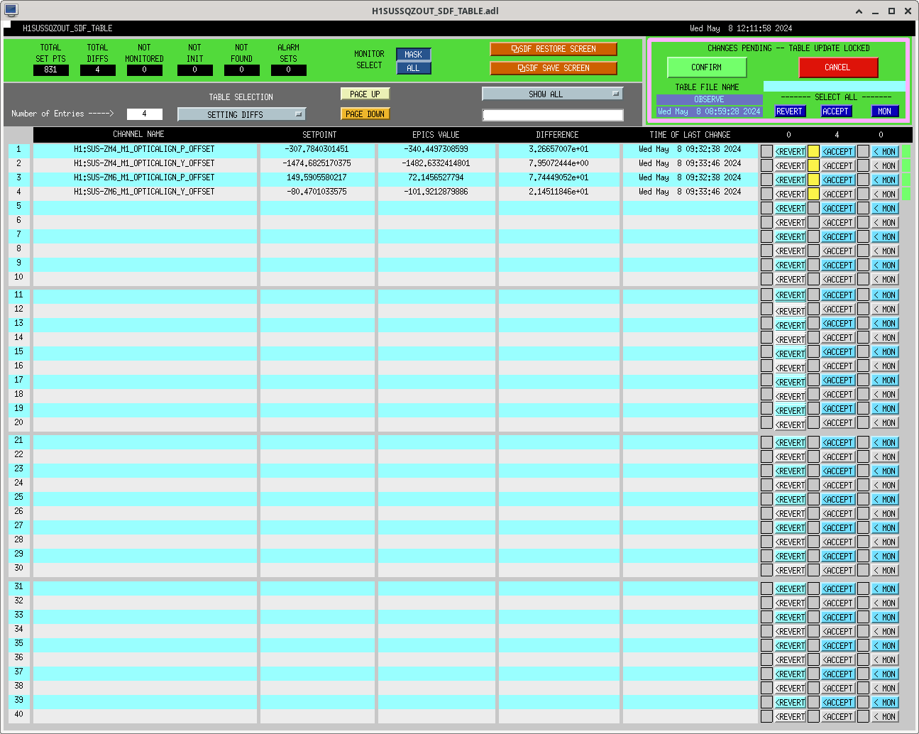
The AS_A Y offset was turned off before this measurement, and it will stay off. I've accepted this in SDF observe.snap and removed it from ISC_LOCK.


