Took Calibration Sweep at 13ish H1 NLN Lock.
BB Start and End: 15:27 UTC, 15:35 UTC
File Names:
/ligo/groups/cal/H1/measurements/PCALY2DARM_BB/PCALY2DARM_BB_20240912T152702Z.xml
Simulines GPS End and Start: 1410190636, 1410192001
File Names:
File written out to: /ligo/groups/cal/H1/measurements/DARMOLG_SS/DARMOLG_SS_20240912T153646Z.hdf5
File written out to: /ligo/groups/cal/H1/measurements/PCALY2DARM_SS/PCALY2DARM_SS_20240912T153646Z.hdf5
File written out to: /ligo/groups/cal/H1/measurements/SUSETMX_L1_SS/SUSETMX_L1_SS_20240912T153646Z.hdf5
File written out to: /ligo/groups/cal/H1/measurements/SUSETMX_L2_SS/SUSETMX_L2_SS_20240912T153646Z.hdf5
File written out to: /ligo/groups/cal/H1/measurements/SUSETMX_L3_SS/SUSETMX_L3_SS_20240912T153646Z.hdf5
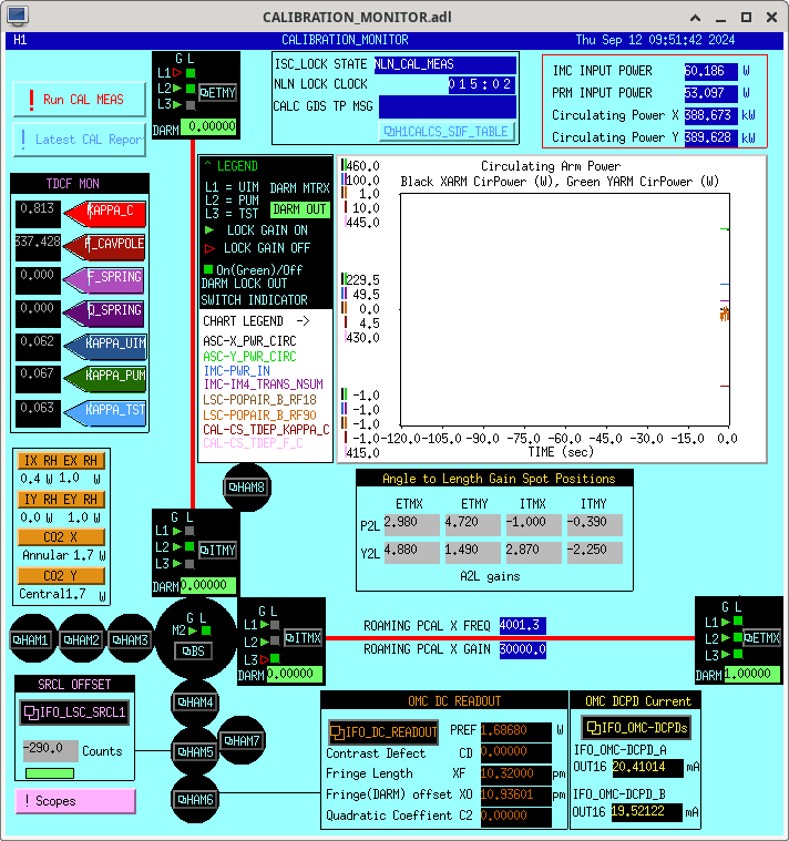
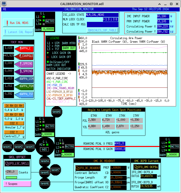
Calibration Monitor Screenshot taken right after hitting run on BB attached.
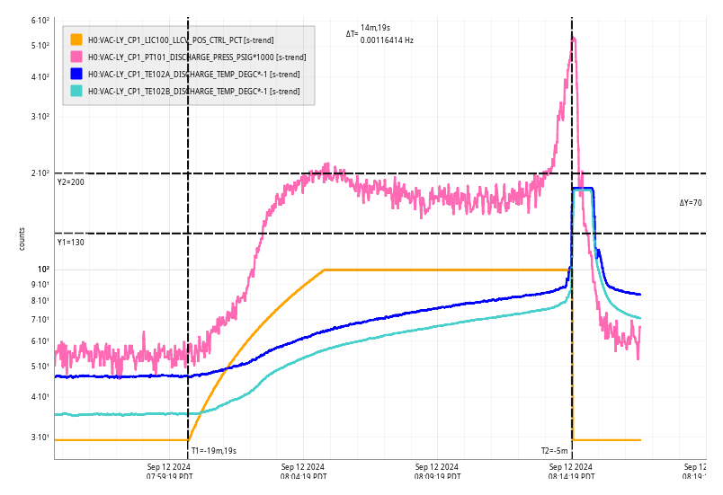
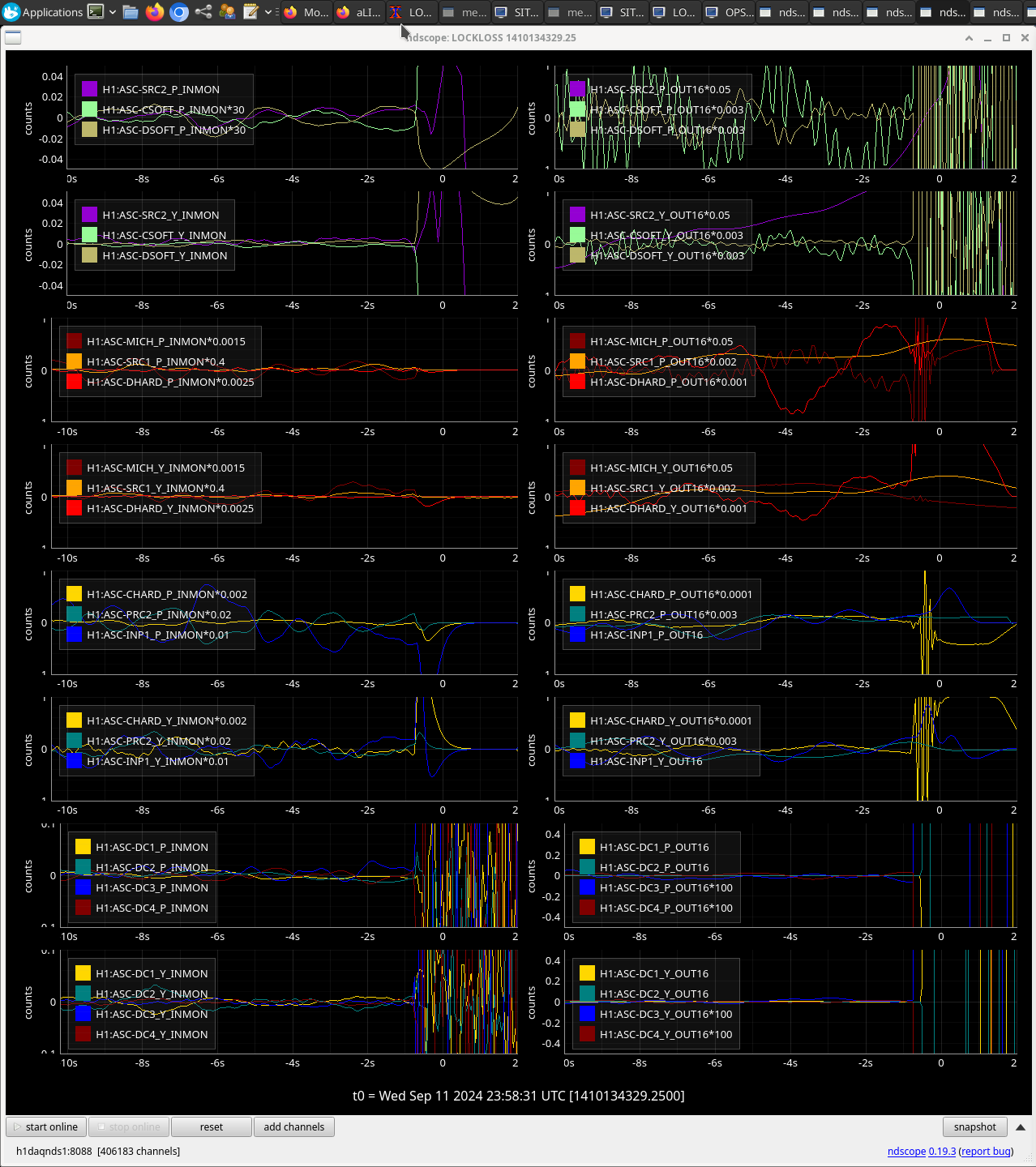
Camilla, Ibrahim and I ran a second set of simulines. This is not a full calibration measurment. Screenshot of the monitor lines attached. Got the following output at the end of the measurement, note the 30 minutes between 'Ending lockloss monitor' and 'File written':
2024-09-12 17:16:07,510 | INFO | Ending lockloss monitor. This is either due to having completed the measurement, and this functionality being terminated; or because the whole process was aborted.

2024-09-12 17:48:05,831 | INFO | File written out to: /ligo/groups/cal/H1/measurements/DARMOLG_SS/DARMOLG_SS_20240912T165244Z.hdf5

2024-09-12 17:48:05,845 | INFO | File written out to: /ligo/groups/cal/H1/measurements/PCALY2DARM_SS/PCALY2DARM_SS_20240912T165244Z.hdf5

2024-09-12 17:48:05,856 | INFO | File written out to: /ligo/groups/cal/H1/measurements/SUSETMX_L1_SS/SUSETMX_L1_SS_20240912T165244Z.hdf5

2024-09-12 17:48:05,866 | INFO | File written out to: /ligo/groups/cal/H1/measurements/SUSETMX_L2_SS/SUSETMX_L2_SS_20240912T165244Z.hdf5

2024-09-12 17:48:05,876 | INFO | File written out to: /ligo/groups/cal/H1/measurements/SUSETMX_L3_SS/SUSETMX_L3_SS_20240912T165244Z.hdf5