Naoki, Nutsinee
Today SQZ_MANAGER failed to go inject freq independent squeezing multiple times. There were a couple of issues:
1) FC ASC engages when the Q error signal went below a certain threshold but didn't actually grab lock. We haven't fixed this one so the problem can repeat. Hopefully we will fix this tomorrow.
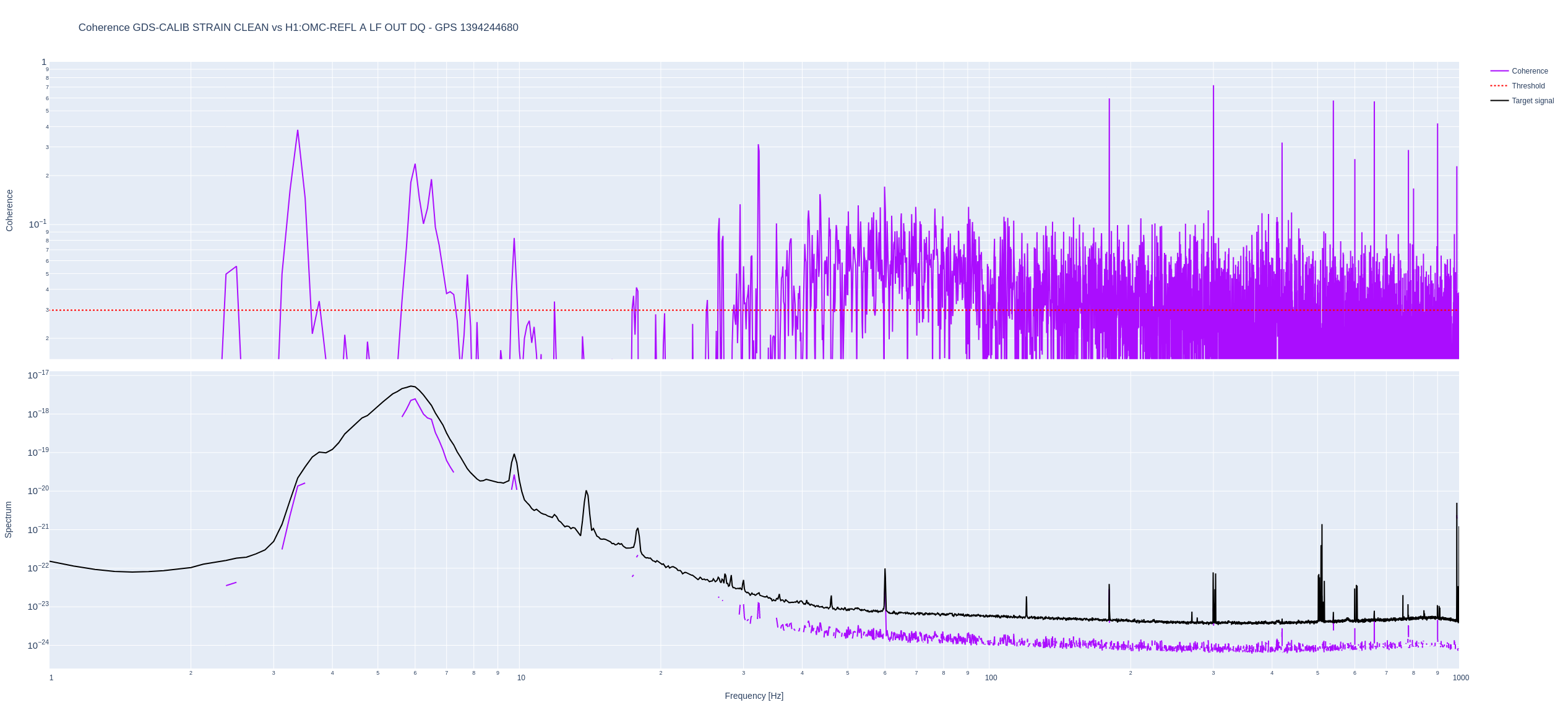
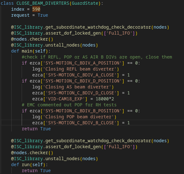
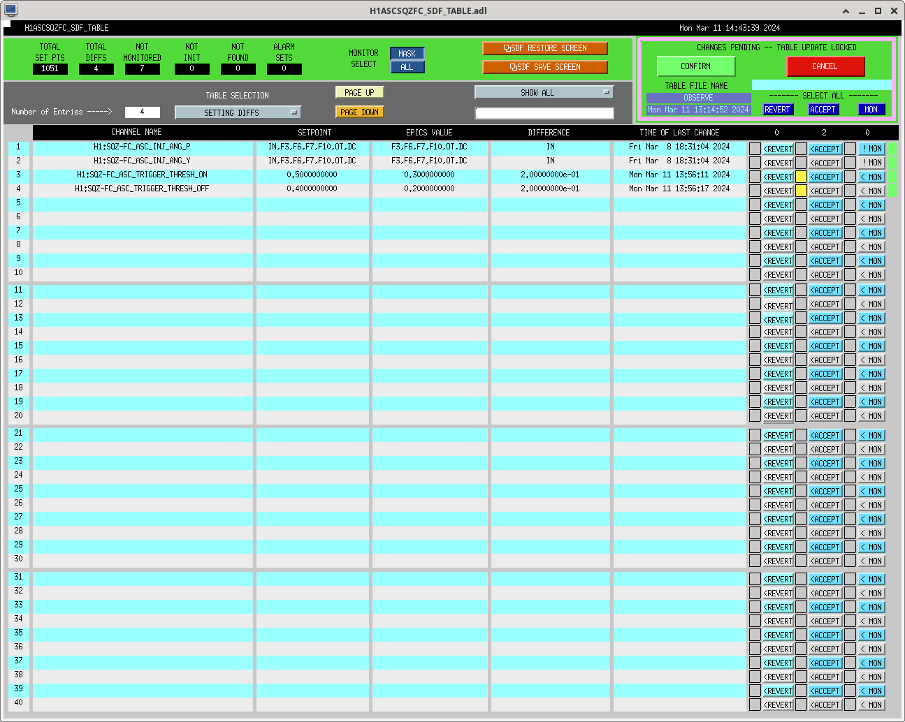
2) SQA_MANAGER waited 2 minutes for SQZ_FC to go to the correct state. See attached screenshot of SQZ_MANAGER, line 532. Without checking to see what's actually going on if the SQZ_FC guardian didn't reach its nominal state SQZ_MANAGER will just close the beam diverter and go to SQZ_READY_IFO. SQZ_FC worked fine most of the time but it just happened to take a little more than 2 minutes to reach its nominal state. The logic needs to be fixed with a loop that checks for FC_LOCK guardian state. For now we bypass the issue by increasing the wait time to 3 minutes.
Quiet time between
PDT: 2024-03-11 19:11:02.319941 PDT
UTC: 2024-03-12 02:11:02.319941 UTC
GPS: 1394244680.319941
and
PDT: 2024-03-11 19:21:42.276196 PDT
UTC: 2024-03-12 02:21:42.276196 UTC
GPS: 1394245320.276196
Used this time to run BruCo: https://ldas-jobs.ligo-wa.caltech.edu/~gabriele.vajente/bruco_1394244680_STRAIN_CLEAN/
Notable coherences:
OMC-REFL_A_LF shows low-ish but broadband coherence with DARM above 30 Hz, and this is suggestive of the excess noise we see now w.r.t. O4a. Evan suggests that this could be 45 MHz sidebands amplitude noise, that dominates the OMC reflection, and has a small transmission through the OMC
comparing OMC_REFL with CLF to now
Atttached is a plot of the power spectrum of OMC-REFL during:
-- blue: REFL 45 O4a ( Janurary 15th 02:25 UTC )
--green: REFL 45 now (March 12th 12:30 UTC )
--brown: REFL 45 with CLF closed ( March 12th 00:24 UTC )
--red: REFL 45 with CLF open (March 12th 01:54 UTC )
Clearly, during O4a, the noise in OMC-REFL 45 was better compared to now. It seems from this is that the noise level does not change with the modulation depth (only looking at a 2 minute stretch); however, the source of the noise difference between CLF open and closed is not known. The noise level also seems to vary over the recent locks, which we cannot explain yet.
I ran a quick bruco on the OMC-REFL_A_LF channel itself, https://ldas-jobs.ligo-wa.caltech.edu/~elenna.capote/brucos/OMC_REFL/
[Gabriele, Elenna]
We have updated the LSC feedforward, and made fantastic use of Gabriele's new interactive fitting tool. All templates and code found in [userapps] isc/h1/scripts/feedforward
We followed the usual procedure:
Attached are screenshots comparing the DARM/SRCL and DARM/MICH injections with no feedforward, old feedforward, and new feedforward.
The new filters are in FM3 for both. Guardian code is updated. No SDF updated for now.
We think this is a new record, with about factor 500 suppression of MICH :)
[Gabriele, Louis, Evan H., Swadha]
After tuning the LSC feedforward and updating the calibration, we took a DARM quiet time to compare with the O4a sensitivity. With the updated calibration, our range sits around 140 Mpc. The attached screenshot shows a comparison between cal delta L on January 7th to today. Louis walked me through updating the DARM calibration for both traces to make sure it was accurate. I chose Jan 7 because it appeared to be a time of a recent, decent sensitivity in O4a (around 160 Mpc). Our low frequency noise does not appear to have changed significantly. The reduction in range seems to come from the mid-range region where adjustments in the squeezing would probably help.
Template saved in /ligo/home/elenna.capote/DTT/DARM_compare_O4a_b.xml
Both of these times are with OM2 cold.
J. Kissel, L. Dartez Jeff ran the calibration measurement suite. We processed it according to the instructions here. I then updated theCAL_DELTAL_EXTERNAL
calibration using the new report at/ligo/groups/cal/H1/reports/20240311T214031Z
.
Attaching the cal report. Optical gain: 2024-03-12: 3.322e+06 [DARM ERROR counts / meter] 2023-10-27: 3.34e+06 [DARM ERROR counts / meter] KappaC at the end of O4a: 1.006 Optical gain at end of O4a: 3.336e6 [DARM ERROR counts / meter] So the current optical gain is differs from what we had at the end of O4a by about 0.4%.
The calibration from this report has now been added to the LDAS cluster archive such that it shows up in the official infrastructure. It's location is https://ldas-jobs.ligo-wa.caltech.edu/~cal/?report=20240311T214031Z It was tagged as "valid" and "exported" as follows: On a local control room workstation (or on whichever computer system the report was created) $ cd /ligo/groups/cal/H1/reports $ touch 20240311T214031Z/tags/exported $ touch 20240311T214031Z/tags/tags $ arx commit 20240311T214031Z
Matt, Stefan, Jennie W
Overall: We adjusted the OMC input matrix resulting in a factor of ten reduction in the OMC suspension drive.
The procedure is as follows:
1) Start by calculating the sensing matrix which maps OM3 and OMC degrees of freedom to QPD A and B changes for one of the suspension degrees of freedom (pitch or yaw).
2) Calculate the inverse of the sensing matrix, which will give you a possible input matrix, mapping QPDA and B changes to OM3 and OMC changes which we use for feedback. The first row of the matrix maps only to OM3, for example, which we chose to be our primary degree of freedom with the higher bandwidth. The trouble we were finding before is that the inverse of our sensing matrix yields a strong degeneracy between the two degrees of freedom, and so we push our second row in the direction that cancels most of the noise in the error signal, and also reduces the degeneracy between the error signals.
This procedure can then be repeated for the other degree of freedom (pitch or yaw).
The results of the noise reduction can be seen in the time domain as well.
Jennie, Craig Today we reran the mod-depth up down tests. We are not fully trusting these numbers because we suspect we are clipping a bit on IM4_TRANS, which might artificially raise all of our estimated PRGs, including those for RF9 and RF45. Additionally, there was obvious thermalization still happening during the measurement. Still, the first pass measurement is useful for up to 10% estimates? We should rerun after we recenter on IM4. PRGs 9 MHz PRG = 85.6 45 MHz PRG = 36.6 Carrier PRG = 50.4 REFL ratios 9 MHz reflection ratio = 0.309 45 MHz reflection ratio = 0.268 Carrier reflection ratio = 0.055 Table of relative powers
Channels | 9 MHz | 45 MHz | Carrier |
---|---|---|---|
H1:IMC-PWR_IN_OUT16 | 0.013 | 0.015 | 0.972 |
H1:IMC-IM4_TRANS_NSUM_OUT16 | 0.013 | 0.015 | 0.972 |
H1:LSC-REFL_A_LF_OUT16 | 0.065 | 0.065 | 0.870 |
H1:LSC-REFL_B_LF_OUT16 | 0.063 | 0.062 | 0.874 |
H1:LSC-POP_A_LF_OUT16 | 0.022 | 0.011 | 0.967 |
H1:ASC-POP_A_NSUM_OUT16 | 0.021 | 0.011 | 0.968 |
H1:ASC-POP_B_NSUM_OUT16 | 0.021 | 0.011 | 0.968 |
H1:ASC-AS_C_NSUM_OUT16 | 0.181 | 0.521 | 0.298 |
H1:ASC-OMC_A_NSUM_OUT16 | 0.174 | 0.637 | 0.189 |
H1:ASC-OMC_B_NSUM_OUT16 | 0.180 | 0.565 | 0.255 |
H1:ASC-X_TR_A_NSUM_OUT16 | 0.008 | 0.009 | 0.983 |
H1:ASC-X_TR_B_NSUM_OUT16 | 0.008 | 0.009 | 0.983 |
H1:ASC-Y_TR_A_NSUM_OUT16 | 0.009 | 0.009 | 0.983 |
H1:ASC-Y_TR_B_NSUM_OUT16 | 0.009 | 0.009 | 0.983 |
For the 9 MHz PRG of 85.6 the nominal level on POPAIR_B_RF18 I phase PD is 1577 counts.
For the 45 MHz PRG of 36.6 the nominal level on POPAIR_B_RF90 I phase PD is 399 counts.
Trent, Georgia
We wanted to see how the arm cavity higher order modes changed with squeezing phase, so we plotted Dhruva's data from 19 February 2023 zooming in on the appropirate frequency range. See Dhruva's post for more info about the data. We have two plots, one at higher frequency (10200Hz - 10900Hz) (02 20 modes) and one at lower frequency (5000Hz - 5700Hz) (01, 10 modes).
Note that for the high frequency plot, the y-arm HOM is degenerate with the acoustic modes of the test masses (at ~10.4kHz) and the acoustic modes dominate the signal at this frequency. Therefore, we can't say much about the squeeze angle dependance of the y-arm HOM but the x-arm HOM amplitude does not seem to change with the squeeze angle.
The low frequency plot also does not show a significant change in the HOM amplitude.
The list below gives the GPS times and the corresponding curve colors.
Ref 0: 1360822152 (Red)
Ref 1: 1360822844 (Blue)
Ref 2: 1360823864 (Green)
Ref 3: 1360824833 (Brown)
Ref 4: 1360825873 (Pink)
Ref 10: 1360834978 (Teal)
A nice DARM video is found in this post which shows the arm HOM shifting in frequency as the test masses thermalize.
I made a Dan-style DARM movie of the second order arm transverse modes during the squeezer phase adjustments, in case there is something we missed with the PSDs. The noise at 10k goes up and down with squeezing and anti-squeezing, but the modes dont seem to be affected.
TITLE: 03/11 Day Shift: 15:00-23:00 UTC (08:00-16:00 PST), all times posted in UTC
STATE of H1: Commissioning
INCOMING OPERATOR: None
SHIFT SUMMARY:
15:00UTC Started off the day in a Manual Initial Alignment
For the intial alignment this morning, yarm was found by hand and we had to lower the locking threshold from 0.7 to 0.5 from the ALS YARM PHD medm screen (this was reverted shortly after). To get MICH_BRIGHT to lock I had to move the BS quite a bit in Pitch (>2 microradians), for SRC locking guardian prompted me to center SR2 by hand so I misaligned SRM and adjusted SR2 to center it on AS-AS_C, which I had to move a lot in pitch again (312.2 -> 292.7).
16:30UTC After finishing IA Shiela start to work on the OMC suspension IM alignment / saturation issue
18:20 ISI HAM7 WD tripped, probably from SQZ rack workpause
Struggled to lock DRMI or PRMI even after CHECK_MICH, so we started another IA at 18:50UTC finished at 19:14UTC, Locked DRMI on the first try after this IA
Lockloss at 21:14
Struggled to get good buildups with PRMI, ASC would kill it. I tried to hold at PRMI_LOCK and touch up the BS and PRM by hand looking the slow building ups scope but I was not able to do it effectively/fast enough?
I'm starting another IA at 22:25UTC which is still ongoing as of 00:0UTC and almost finished
LOG:
Start Time | System | Name | Location | Lazer_Haz | Task | Time End |
---|---|---|---|---|---|---|
15:01 | FAC | Karen | Optics lab | N | Tech clean | 15:32 |
17:35 | FAC | Kim | MidX | N | Tech clean | 18:17 |
17:35 | FAC | Karen | MidY | N | Tech clean | 18:18 |
17:58 | SAF | Chris | FCES | N | Safety checks | 18:58 |
18:14 | SQZ | Nutsinee | SQZ racks | N | Transfer functions | 19:14 |
20:07 | FAC | Tyler | EndY | N | Check | 21:07 |
22:04 | SQZ | Nutsinee | SQZ racks | N | Transfer functions | 22:25 |
https://ldas-jobs.ligo-wa.caltech.edu/~lockloss/index.cgi?event=1394230513
DCPD saturation then LL
I updated the LSC CAL CS filters with changes to the MICH, PRCL and SRCL actuation. This ensures that we can accurately use the CAL CS channels to understand the LSC noise coupling to DARM, among other benefits.
For PRM and SRM (PRCL and SRCL actuators), the big change was Gabriele's improvement of the offload filters on M1. I rearranged filters in the CAL CS bank to line up with the filters as they are in the mirror locking bank. All the changes occured in the CAL CS control path M1 filters for PRM and SRM- I moved the M2M3lock and sus_um filters to be in FM3 and FM4 respectively, and rearranged the current offloading filters into FMs 1, 2, 6, 7 and 10 to match PRM/SRM offloading structure. As a reminder, PRCL and SRCL actuation occurs from M3 and M1, and there is a gain of 10 in the M2 locking bank but the lock outswitch is OFF.
For MICH, I incorrectly included an M3 locking filter, the 200:1 filter, but Sheila showed me that cancels out something in the ISC input signal bank, so that is not necessary to account for. More importantly, I engaged the sqrt(1/2) filter that accounts for our MICH actuation from the beamsplitter. I also rearranged filters according to their placement in the beamsplitter locking banks.
I also found some output switch off in the SRM CAL CS bank, so I engaged that.
I have SDFed these changes accordingly, see attached screenshots.
I have also attached screenshots of the LSC CAL CS filter banks for the BS, PRM and SRM control. Reminder, these settings are SDFed in SAFE only.
This should actually be a sqrt(2) correction instead of sqrt(1/2) correction. I have edited the corresponding filters.
FAMAS 26234 PSL Status Report -Weekly
Laser Status:
NPRO output power is 1.821W (nominal ~2W)
AMP1 output power is 67.71W (nominal ~70W)
AMP2 output power is 140.0W (nominal 135-140W)
NPRO watchdog is GREEN
AMP1 watchdog is GREEN
AMP2 watchdog is GREEN
PMC:
It has been locked 10 days, 20 hr 55 minutes
Reflected power = 16.4W
Transmitted power = 109.5W
PowerSum = 125.9W
FSS:
It has been locked for 0 days 0 hr and 39 min
TPD[V] = 0.8063V
ISS:
The diffracted power is around 2.6%
Last saturation event was 0 days 0 hours and 40 minutes ago
Possible Issues: None
We reran the DARM offset step test around GPS 1394062645, similar to alogs 71913, 68870, 64974.
Our current measured contrast defect is slightly higher than in alog 71913, but overall pretty similar.
Matt will comment with the calibration of X0 offset cts into picometers.
Contrast Defect: 2.1 mW
Nominal Total Amps from DCPDs: 40 mA
Responsivity = e λ / c h = 0.858 A/W
Nominal Total Power on DCPDs: 46.6 mW
Nominal Homodyne Angle: 12.2 degrees
To get the offset in picometers from this plot, we use the quadratic factor from the fit, b, along with P_AS, and the contrast defect.
Using the data at 255Hz we find b = 0.672 mW / pm^2, P_AS = 46.6 mW, P_junk = 2.058 mW, which we then use to calculate the offset DeltaL_DC which we call x.
P_as - P_junk = P = ax^2
g = dP/dDeltaL_DC = 2ax
P = b g^2 = 4a^2bx^2 = ax^2, therefore 4ab = 1
We can then solve for x = 2 sqrt(P * b) = 2*sqrt( (46.6mW-2.058mW) * .672 pm^2/mW) = 10.94 pm
We can also calculate the mW / pm^2 [a] factor from the product of interferometer parameters: PRG, SRG, P_in, Reflectiviity of the arms, and the wavenumber; only I did not know them at the time (except the wavenumber).
I want to clarify here that 40 mW is the nominal DCPC power for O4a and now. I trended the DCPD sum output for the recent lock and the many months of O4a to confirm this is true.
OMC DCPD SUM has units of milliamps. One must divide by the responsivity to get milliwatts, which we have done here.
Matt, Criag, Sheila
We want to use this DARM offset stepping to look at the mode matching of the OMC.
In alog71141, Sheila stepped the DARM offset and looked at the OMCrefl power [H1:OMC-REFL_A_LF_OUT16] in order to estimate the mode matching level, which was estimated to be around 96% for cold OM2 [GPStime = 1371902599], and 85% for hot OM2 [GPStime = 1371910040]
When we looked at the same channels during this recent DARM offset step (3/9/24) [GPStime = 13940633389] we see much less change in the OMCrefl, which may be interpreted as better mode matching than the previous cold OM2. Because I cannot resolve any power changes in the noise, it is hard to give a percentage for the mode matching figure but we expect better than 96%.
A couple of notes on the recent DARM offset OMC reflected power: the reflected power is higher than before, as well as the noise, which may be concealing some of these power changes; another thing to note is the time spent ramping on each DARM step, which was much shorter in the previous analysis, and having a slower step may lead to less prominent power fluctuations in the OMCrefl.
change in HAM6 throughput estimated by AS_C
As done in Sheila's alog where she estimates the excess HAM6 losses, I have estimated that we have an additional 10% loss in HAM6 throughput.
Adding up the known losses for HAM6 we expect the throughput to be around 97%
Calibrating DCPD_SUM into mW and dividing by its change from DARMoffset by the AS_C change, we can estimate the losses in the OMC; the DCPDsum change was around 40.4 mW, while the AS_C change was around 46.3 mW, this gives us a ratio of 87%.
Given the ideal throughput of HAM6 being around 97% given known losses [ 0.993(OM1)*0.985(OM3)*0.9926(OMC QPD) = 97% ], this means that we have an additional 10% of losses in the OMC.
DCPD_SUM is converted from mA to mW by the responsivity: 0.858 mA/mW.
Using alogs 47217 and 45734 as a guide, we measured/calculated a new
OMC-DCPD_MATRIX.
Note: this might have to be redone if we update the anti-TIA filtes for the DCPDs, see alog 76228.
We measured the coherent signal amplitude ratio g = PD_A/PD_B above 30Hz (i.e. above the TIA transfer function imbalance), so the matrix is optimized where we actually care.
g=
1.0471
We measure the shot noise signal amplitude ratio h = PD_A/PD_B above 400Hz to avoid thermal noise and correlations from the feedback.
h=1.0247
This produced the new output matrix (see secript)
0.99861 1.00139
0.97725 -1.02328
For reference, old matrix:
0.99963 1.00040
0.98198 -1.0184
The new matrix was loaded, but not yet tested - the IFO lost lock due to 43kts wind gust.
J. Kissel, S. Ballmer, The ISC_LOCK guardian "SDF REVERT" state pushes the safe.snap file for the h1omc model (and others) after every lock loss. Stefan had saved the balance matrix numbers in the OBSERVE.snap, but not in the safe.snap. Together, we've saved the numbers to the safe.snap as well now.
SFD forgot the matrix again, so I updated the matrix and saved it to SDF.
THis one is duned for signal matching around 100Hz.
0.99785 1.00215
0.97800 -1.02249
Meashured the transfer function between DCPD_A and DCPD_B usinng a broadband injection. There is a slight frequency-dependent disagreement (0.2dB) between the two diodes, right around 25Hz, where the TIA has its complex poles.
It looks like one or both Anti-TIA filters are slightly mismateched. We won't tweak it today because we don't know with one is the culprit.
this looks to be related to the TIA response drift reported in LHO:75986.
The template used for this measurement can be found here:
/ligo/home/controls/sballmer/20240311/AoverBmeasurement.xml
Note: the max peak-peak deviation between DCPD_A and DCPD_B is 2.5%.
Naoki, Vicky, Nutsinee, Matt
We recovered the FDS and got 4.5dB squeezing in IFO with 40 times more CLF power as shown in the attached figure.
First we restored the ZM1/2/3 and FC1/2 OSEM positions to the values in O4a. Then we found the FC green trans in camera and PD. We aligned FC1 and FC2 and successfully locked the FC green. We went to SQZT8 and centered the green camera and green QPD.
Since we aligned the green QPD, the green QPD offset value is not valid anymore so we removed the beam spot control from FC ASC. We made a flag for the beam spot control in sqzparams and it is set to False now. We also set the ADF servo flag to False since the ADF demod phase might not be correct. After we figure out the optimal green QPD offset and ADF demod phase, we should revert them.
We reduced the FC IR gain from -3.5 to -0.1 and reduced the FC ASC gain from 0.1 to 0.005.
We have not done any PSAMS scan so we will do it next week.
I reduced the FC ASC threshold as shown in the attachment. I also reduced the fcWFS_qDip_lock_threshold in sqzparams from 0 to -50000 although I am not sure if this is useful.
The SQZ-CLF_REFL_LF_OUTPUT is 245uW now and was 5.7uW in O4a so the CLF power is 43 times more now.
Since the vent, we haven't recovered our squeeze in the region of that really improves our range: See Yellow BLRMS around 350Hz.
Checked SHG pump launch is ~20.5 - 21mW at both times and OPO green trans rejected is similar.
Trending our other signals, just see that OMC_TRANS_RF3 and CLF_REFL_RF6 and FC_WFS_A_ locking signal sare much larger, I think this is expected from increased CLF power. The NLG is simular 15.8 now, was 17.3. Plots of Jan 10th and March 9th.
From Minhyo & Preet After changing of OMC control, it might be good to check the signals. (Refer to Jennie's alog: https://alog.ligo-wa.caltech.edu/aLOG/index.php?callRep=76126, https://alog.ligo-wa.caltech.edu/aLOG/index.php?callRep=76103) Figures are comparison between Mar. 5 and one of the date in O4a (Jan. 2. 2024): 1) SUS-OM3_LOCK comparison with both PIT and YAW 2) SUS-OMC_ASC comparison with both PIT and YAW 3) OMC-ASC_QPD A comparison with both PIT and YAW 4) OMC-ASC_QPD B comparison with both PIT and YAW Seems that the signal went up in high frequency (4 ~ 10 Hz), which is pretty similar with QPD signals.
Update on Mar. 11 After locking of detector, compared the signals between O4a (Jan. 2, 2024, 05:00:00 UTC) and last Sat. (Mar. 9, 2024, 10:00:00 UTC). 1) SUS-OM3_LOCK comparison with both PIT and YAW 2) SUS-OMC_ASC comparison with both PIT and YAW 3) OMC-ASC_QPD A comparison with both PIT and YAW 4) OMC-ASC_QPD B comparison with both PIT and YAW QPD signals went down from the last time (Mar. 5), which is similar to SUS (OM3, OMC) signals.