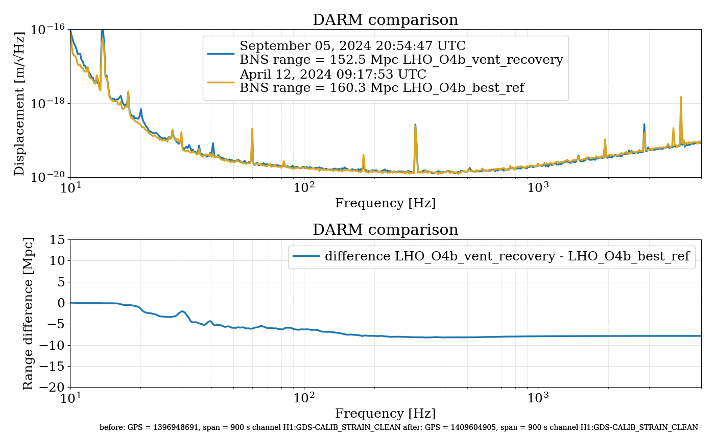
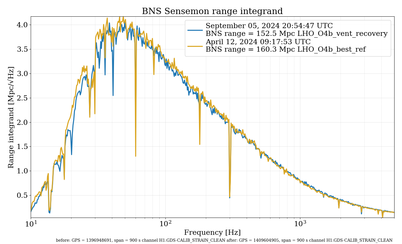
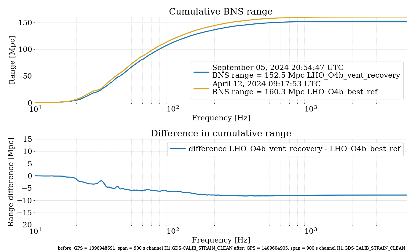
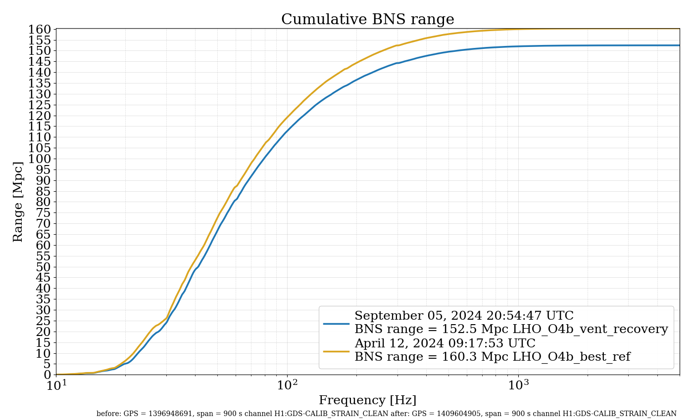
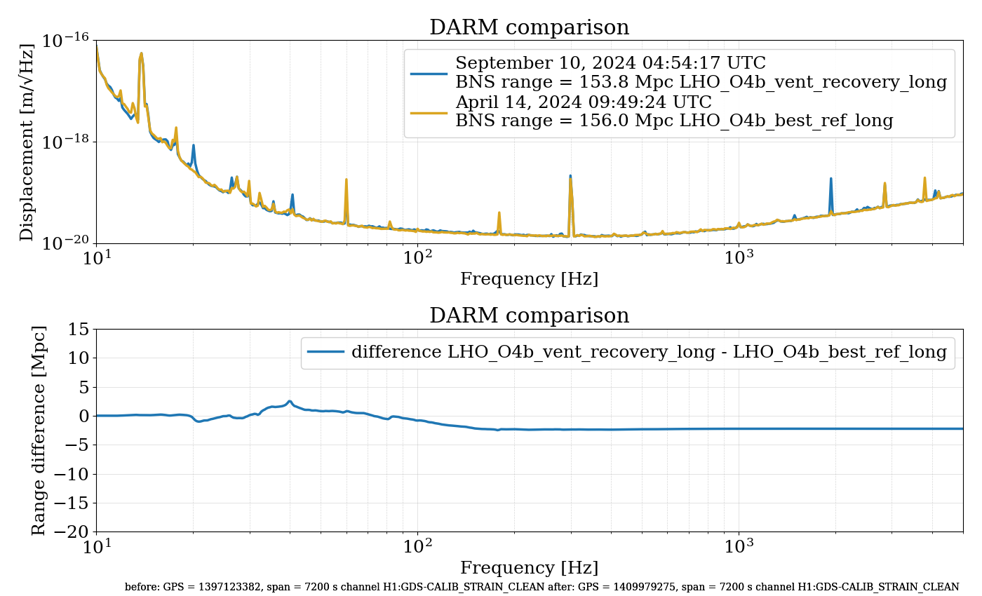
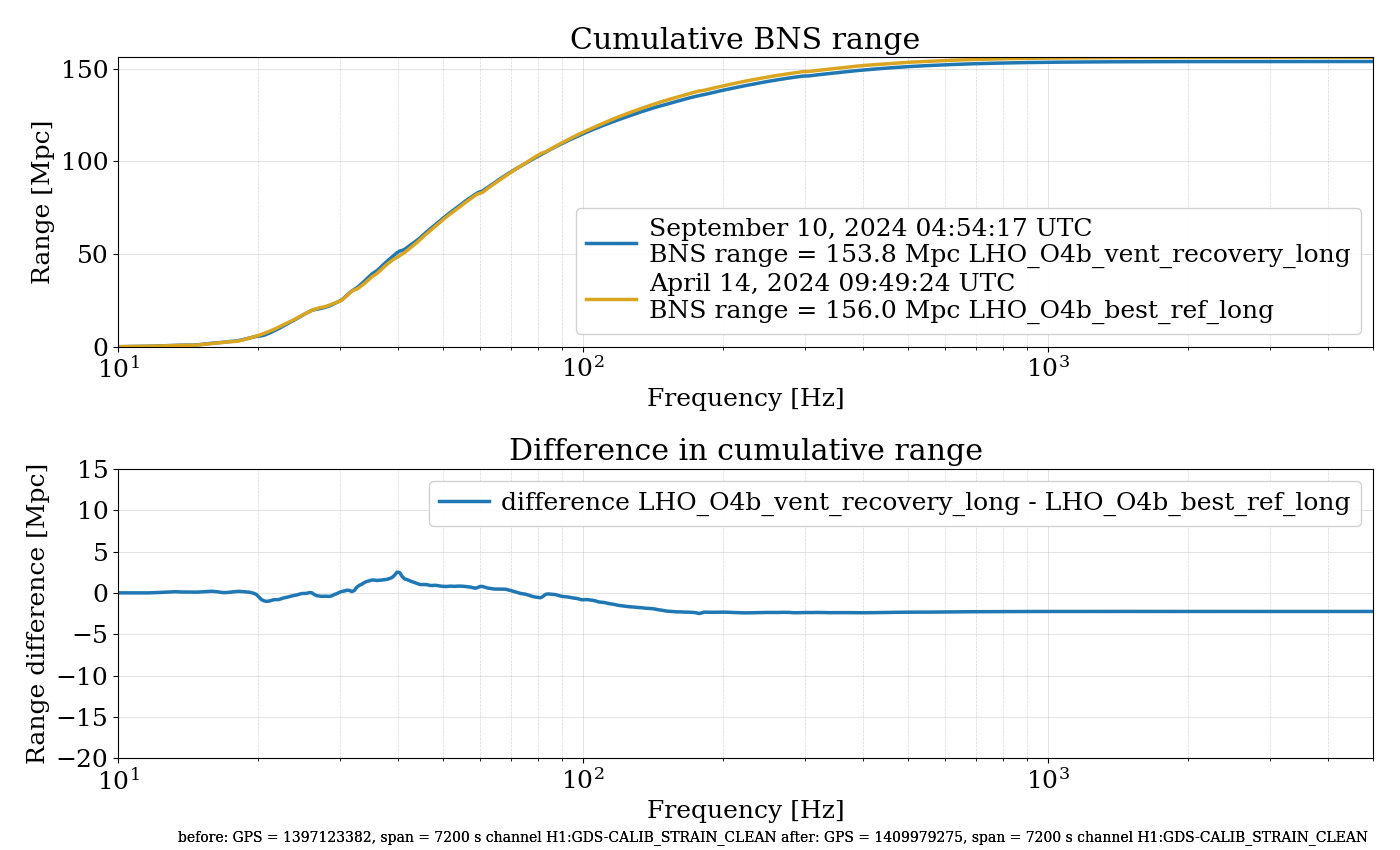
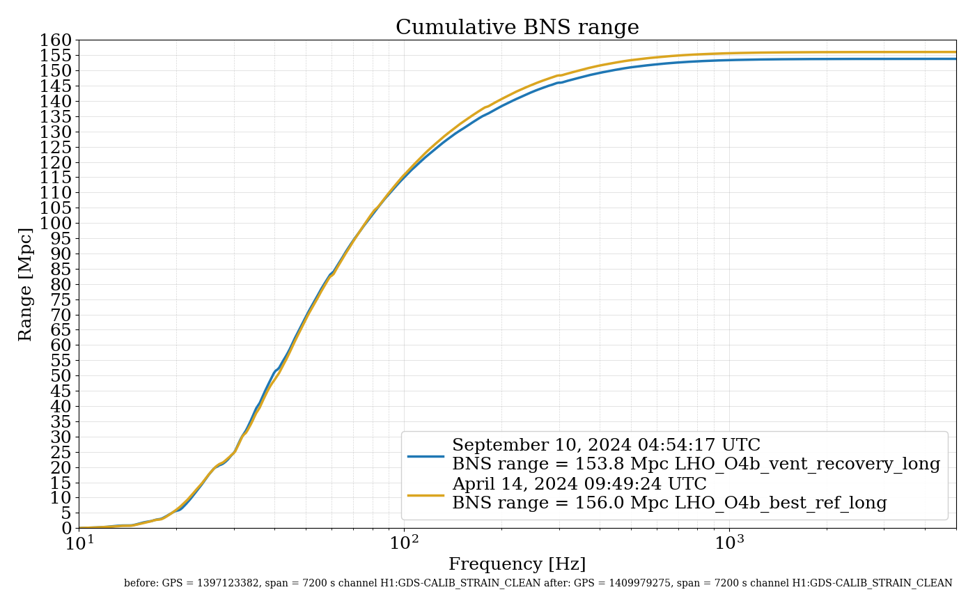
We made some improvements today in the sensitivity, going from about 151 Mpc on GDS CLEAN to about 158 Mpc. However, our best range from April 11th (DARM FOM reference pre-OFI disaster) is around 165 Mpc. I made a comparison of that time and now with today's commissioning improvements to see where we are still missing range. I have attached the four plot results from the darm_integral_compare results (see alog 76935 for directions).
The range integrand plot makes it much easier to see that we are still missing sensitivity around the mid-frequency band. However, the sensitivity difference shows that we lose 5 Mpc of range by 40 Hz as well. Much of this range loss seems to come from a variety of peaks that have appeared since the OFI vent, such as the 20 Hz peak. We lose another ~3 Mpc between 40-200 Hz.
I ran a bruco with GDS CALIB STRAIN CLEAN on high range time after commissioning today: post-commissioning bruco
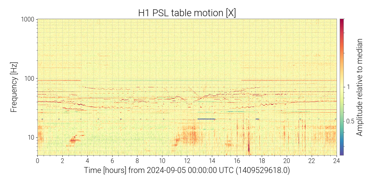
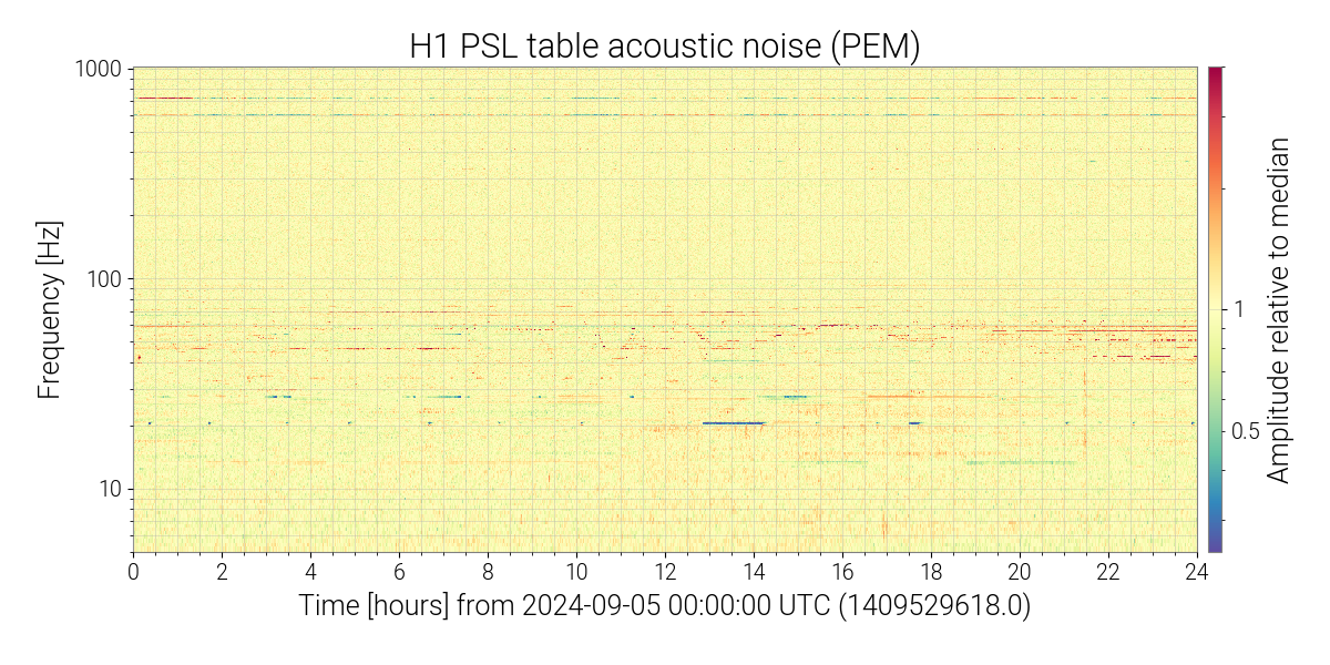
It looks like many of these new low frequency peaks (like the large 20 Hz peak) are well witnessed by things like PSL accelerometers, indicating that they could be from jitter: PEM-CS_ACC_PSL_TABLE1_Y_DQ
Generally, there is a lot of jitter coherence, and given that this is the CLEAN channel, that's probably a sign that the jitter cleaning could be improved, maybe making use of other witness channels if the current witnesses are insufficient to subtract the noise.
A peak at 30 Hz has some coherence with MAG sensor channels, here is one: PEM-CS_MAG_LVEA_VERTEX_X_DQ
Right around 35.4 Hz, there is a lot of coherence with various ISI HAM6 sensors and OMC ASC sensors. For example: ISI-HAM6_GS13INF_V1_IN1_DQ
There is also still a large amount of LSC REFL RIN coherence up to 1 kHz: LSC-REFL_RIN_DQ
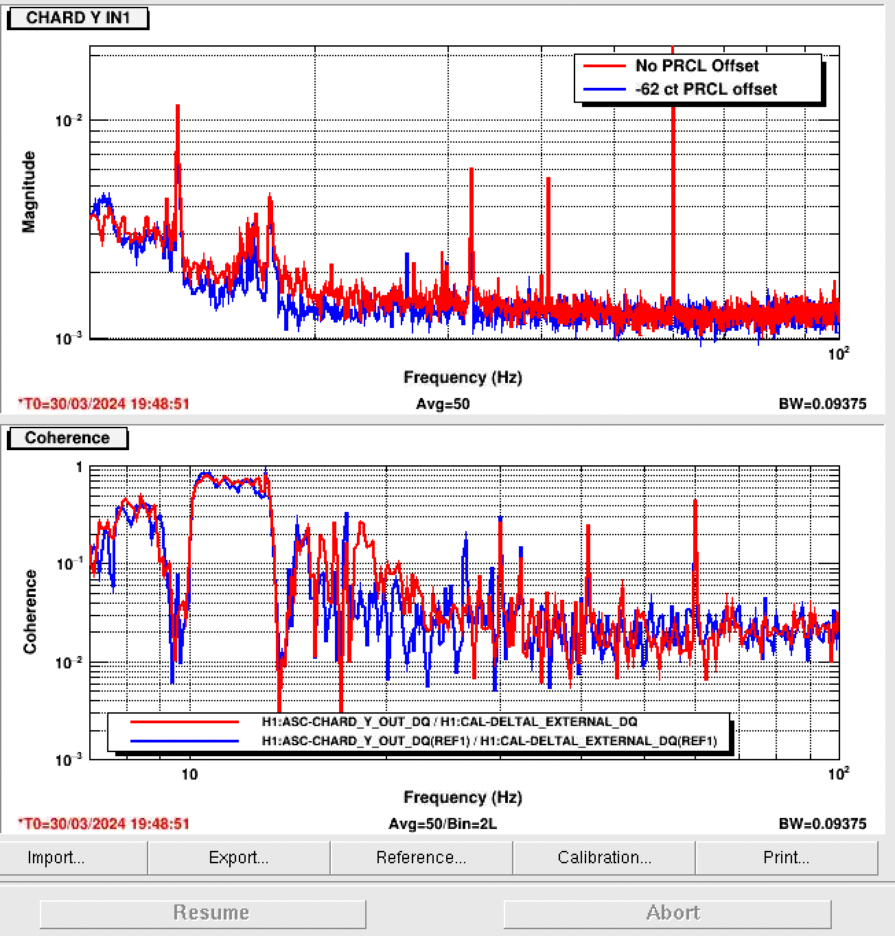
I think we should test the PRCL offset again, especially because this will help reduce the CHARD Y noise coupling (ASC-CHARD_Y_OUT_DQ) and will also possibly help this HF noise (frequency noise? intensity noise?)
SRCL is better than before, but maybe has more room for improvement between 10-25 Hz: LSC-SRCL_OUT_DQ
DHARD Y coherence is low, but still present, so we should be careful with the WFS offset: ASC-DHARD_Y_OUT_DQ
There is still PRCL coherence: LSC-PRCL_OUT_DQ which is likely coupling through a combination of CHARD Y, SRCL, and LSC REFL RIN. Again a PRCL offset will help. Other strategies are to check POP phasing, POP sensing, etc. Reminder: PRCL feedforward failed, so we need to consider other avenues for noise reduction.
To summarize some strategies to get back to April sensitivity:
- check if squeezing can be further optimized in the bucket
- work on improving jitter subtraction, and consider possible low frequency jitter as well
- investigate and improve PRCL coupling through the ASC and possible offsets causing excess frequency or intensity noise
- continue to hunt other low frequency peaks, especially those that are new from the OFI vent
- fiddle with SRCL FF a bit more
Editing because I went back to check the previous PRCL offset work and found this comment: 76818, in short, we can fix the REFL RIN coherence, but it has no effect on the sensitivity. However, it can improve CHARD Y noise, although at the time I don't think we were limited by CHARD Y enough to see the low frequency benefit.