Keita, Sheila
Summary: We chipped the spare KTP crystal this morning, and this afternoon installed the back up spare that Rodica had shipped. We've adjusted the roll, and the pitch angle seems better than the crystal that we removed. So this should be ready to go into the chamber first thing Monday morning. We have many photos from today, which will be attached and annotated to this alog later.
Following on From Jason's alog 79319
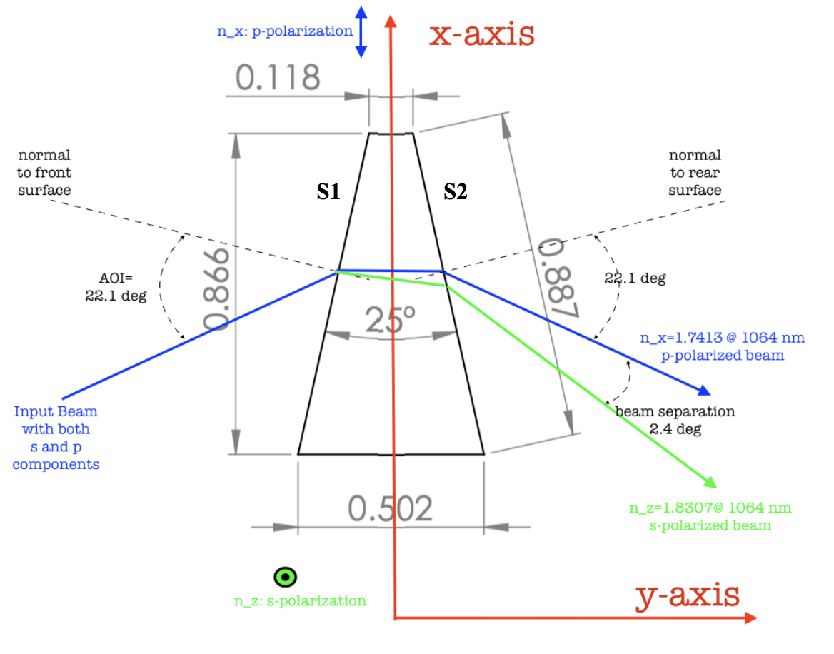
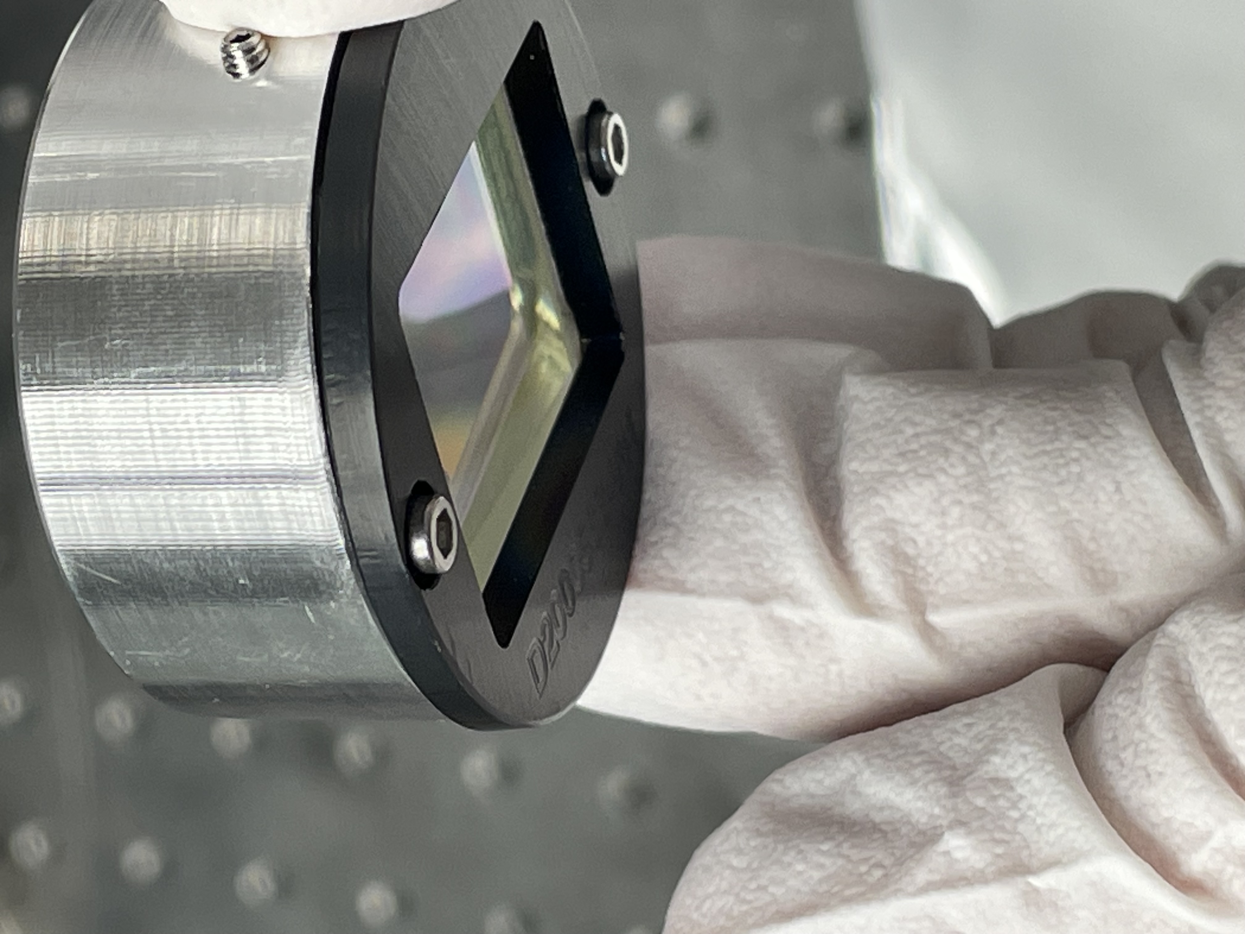
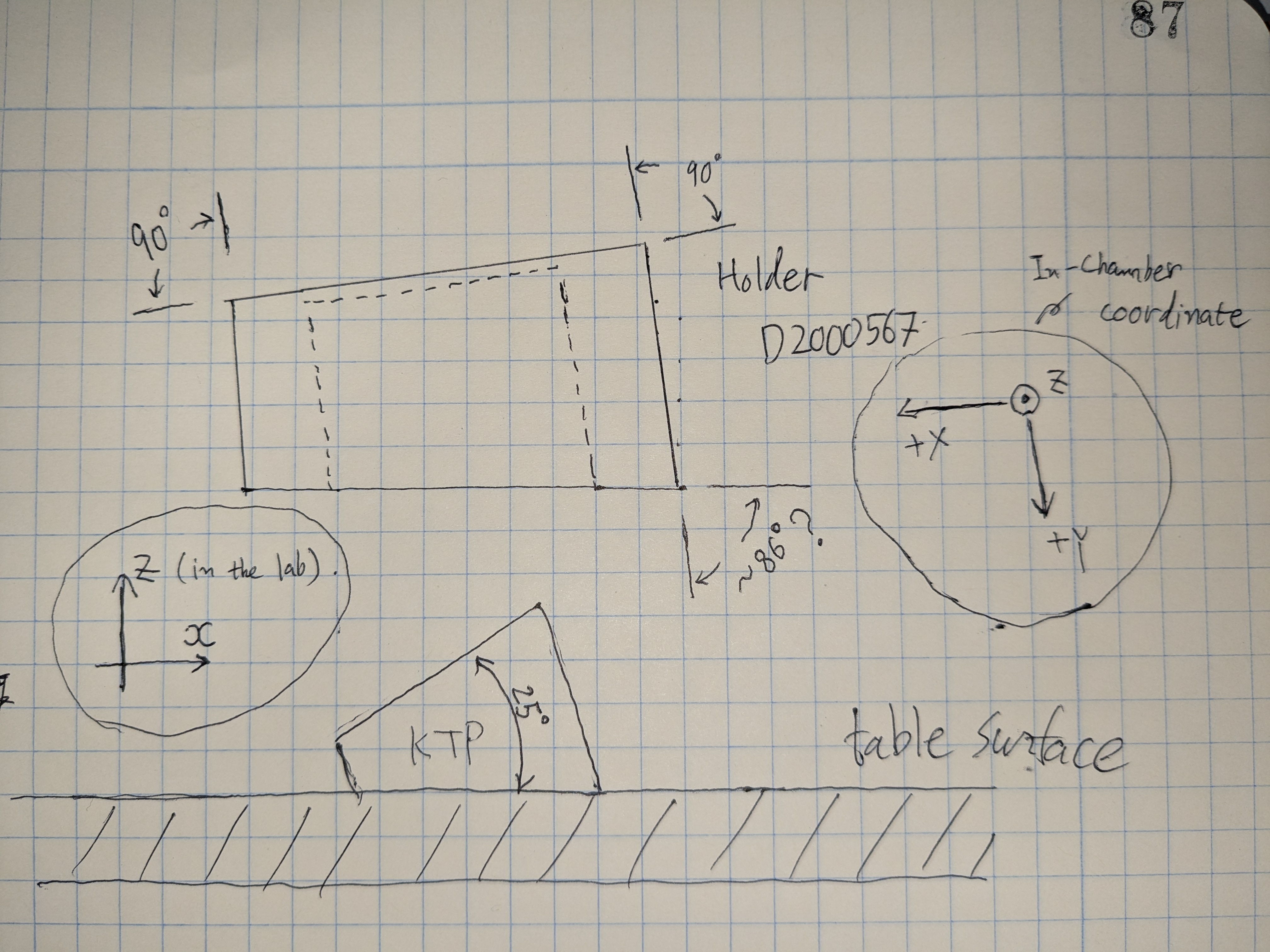
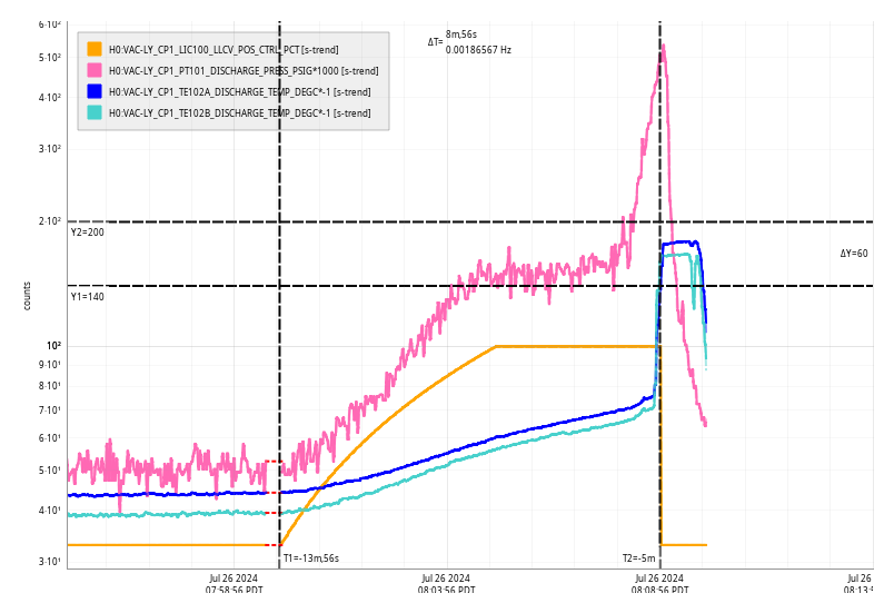
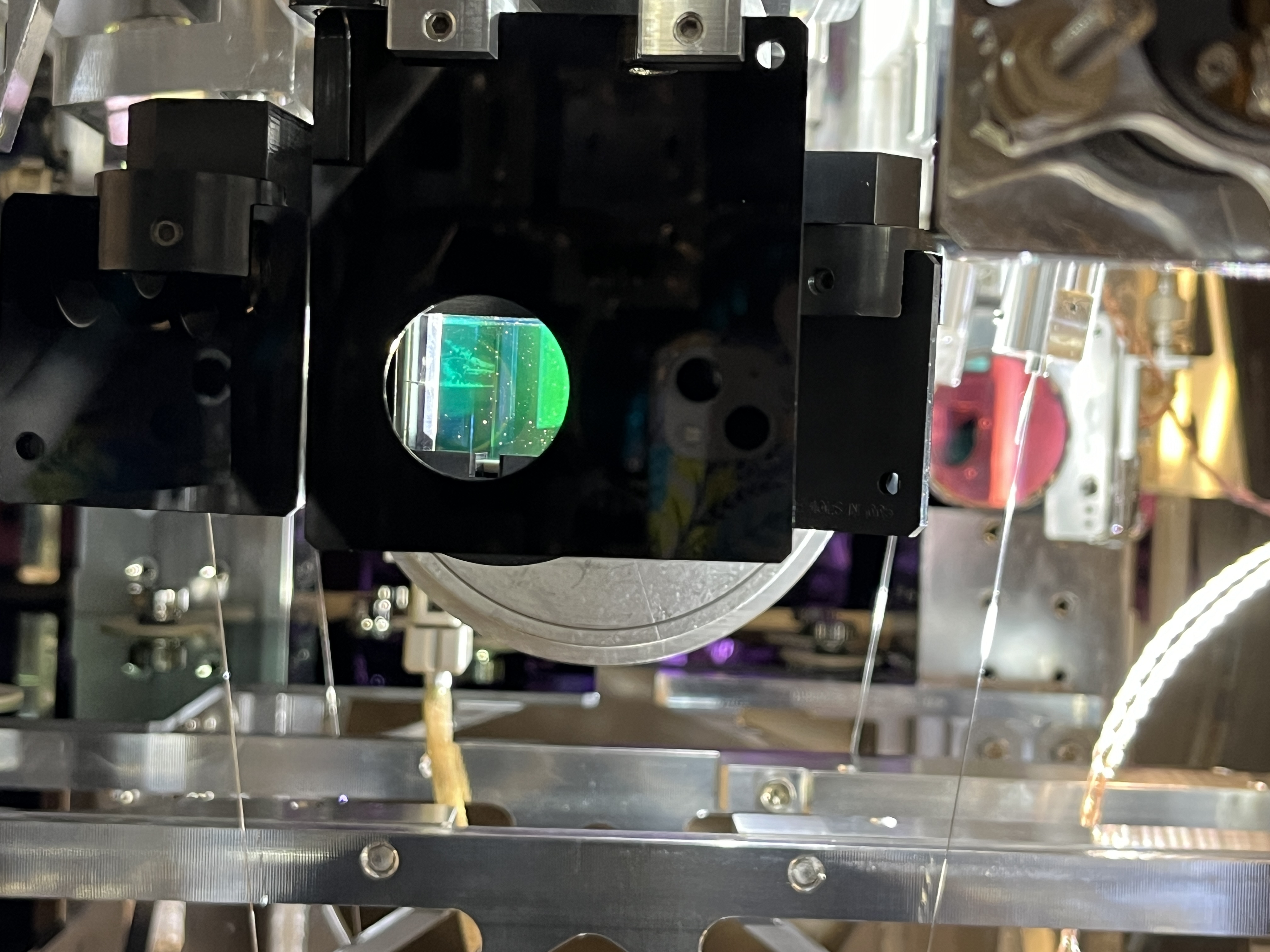
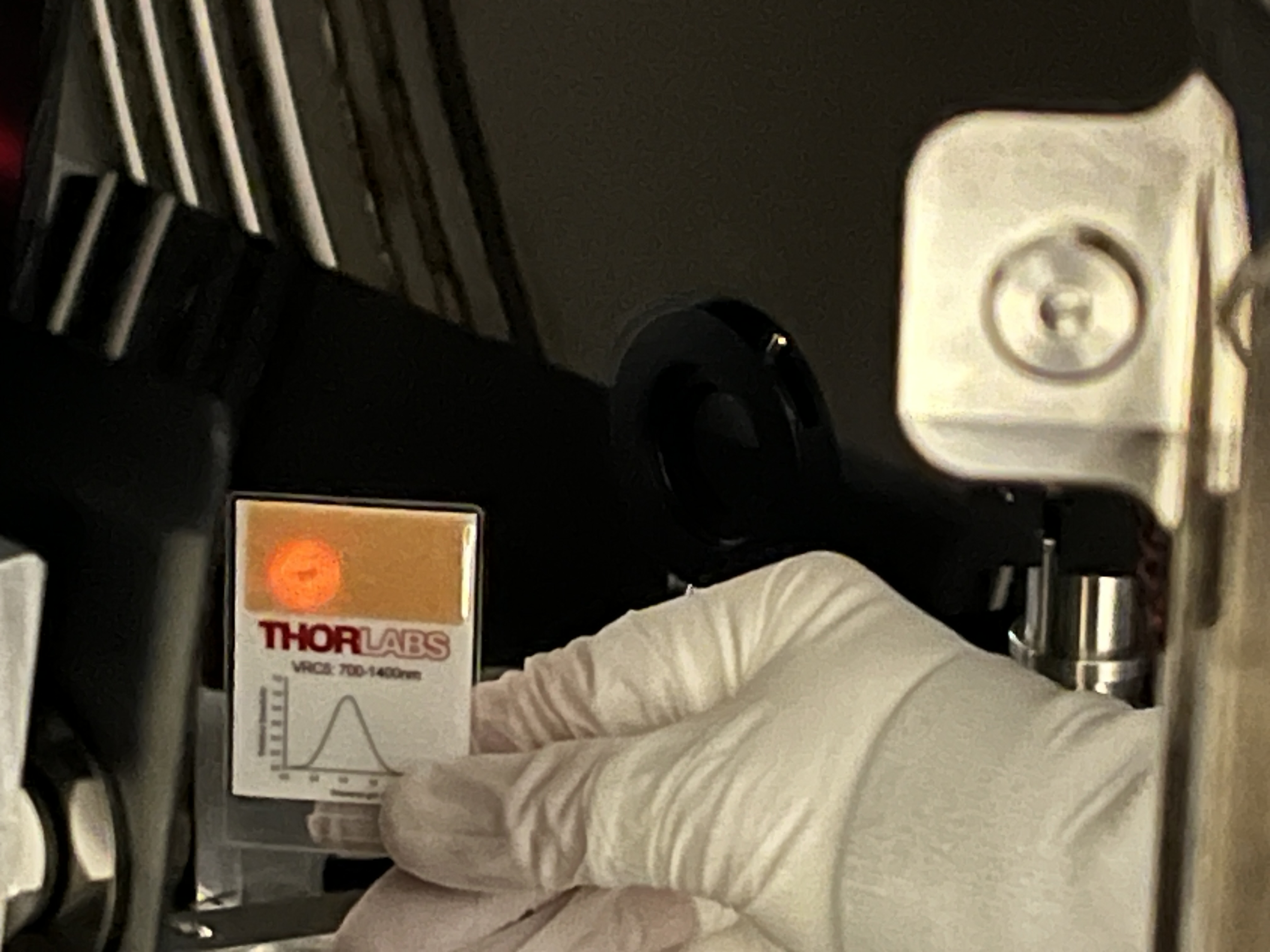
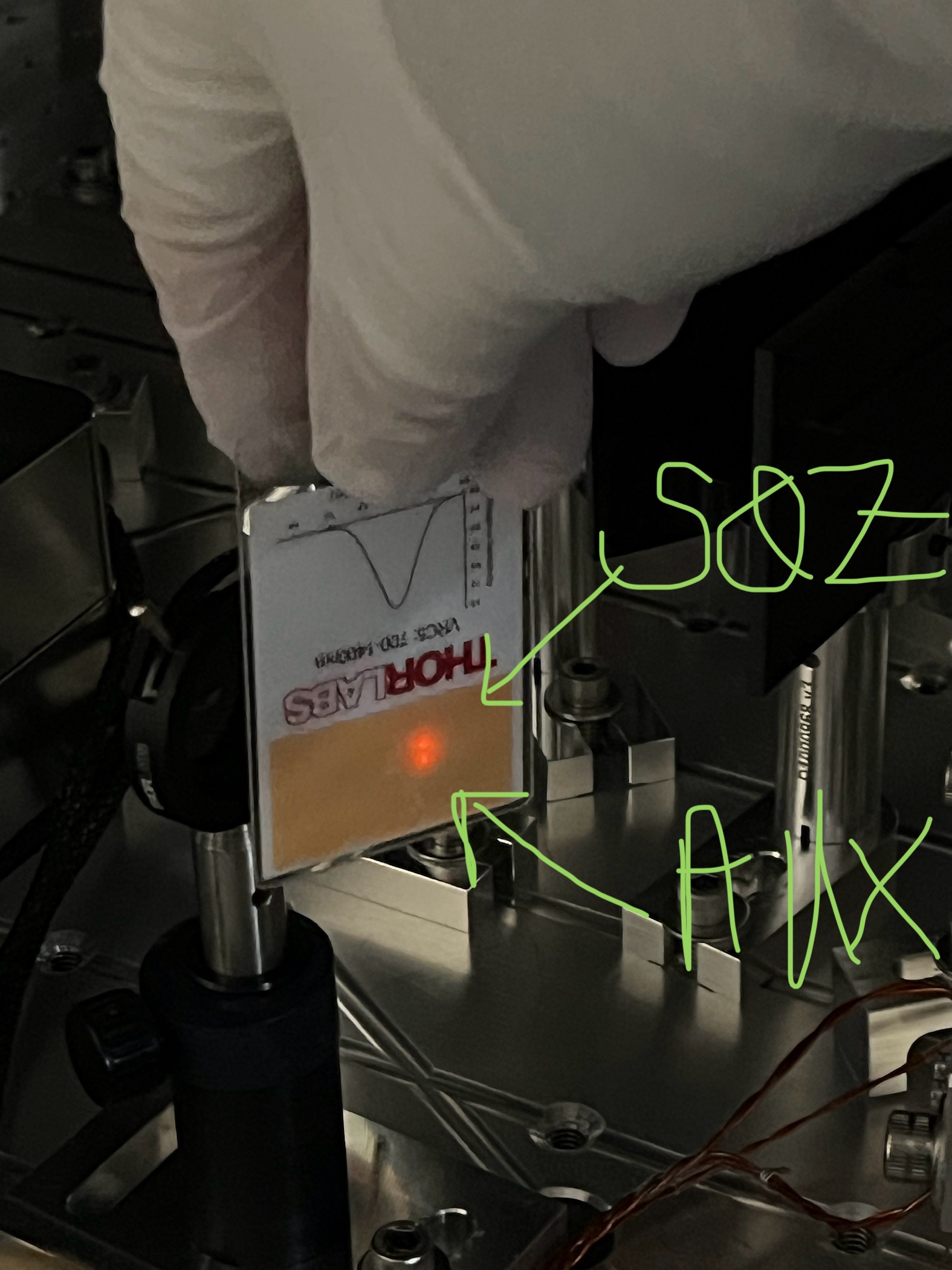
With this placement of the damaged KTP in it's assembly, where the assembly is bolted perpendictular to the beam path, and a wave plate to mix the polarizatoins upstream of the KTP, we have 13.5mW in the p polarized beam (see first attachment which is a diagram Paul sent us this morning), 16.3mW in the s polarized beam, and 2.3 mW in the AR surface. This is not set up with the AOI that the AR coating is designed for, which is why the AR beam is large, we can take advantage of this to set the pitch by setting the AR reflection parallel to the table..
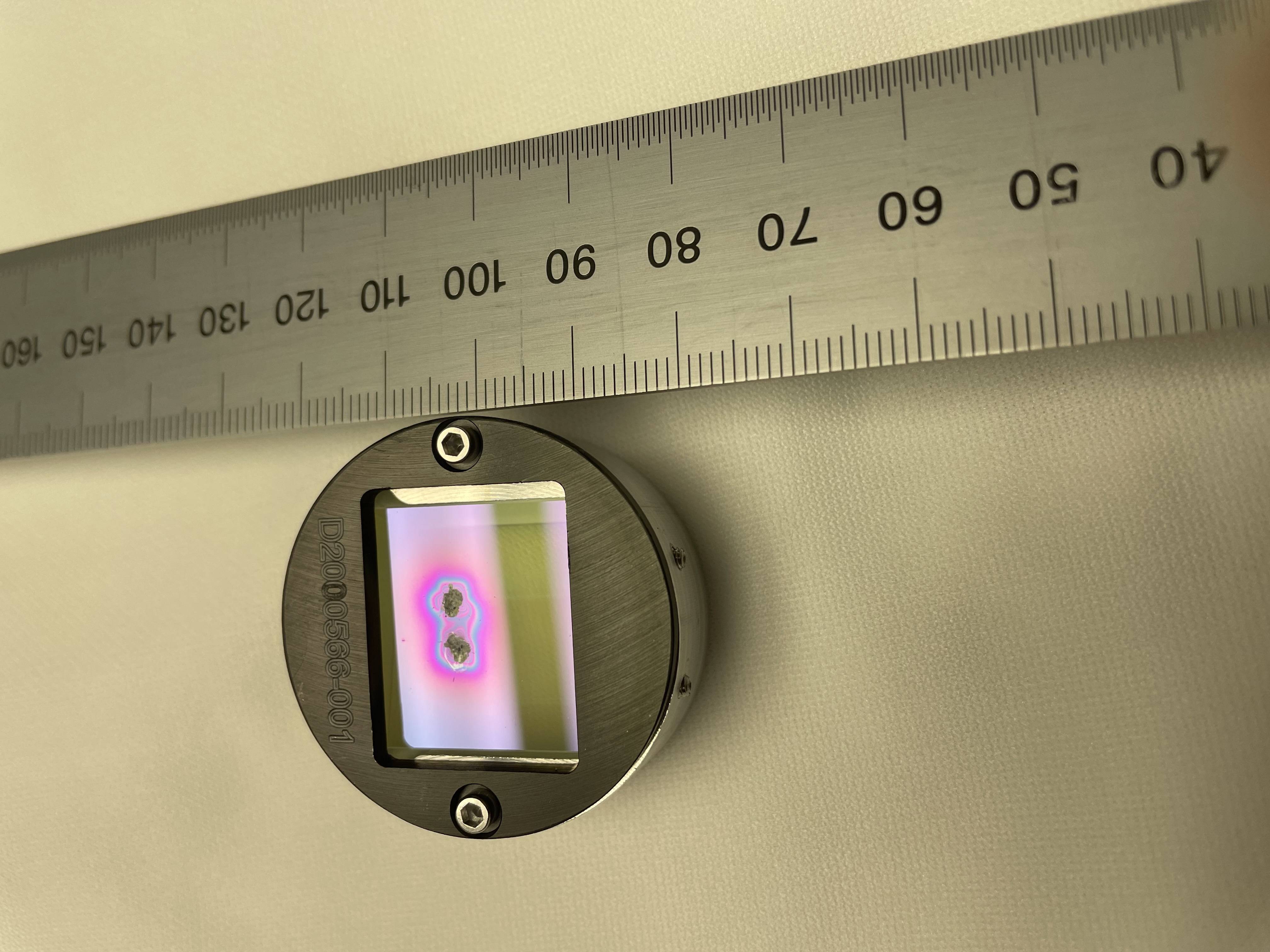
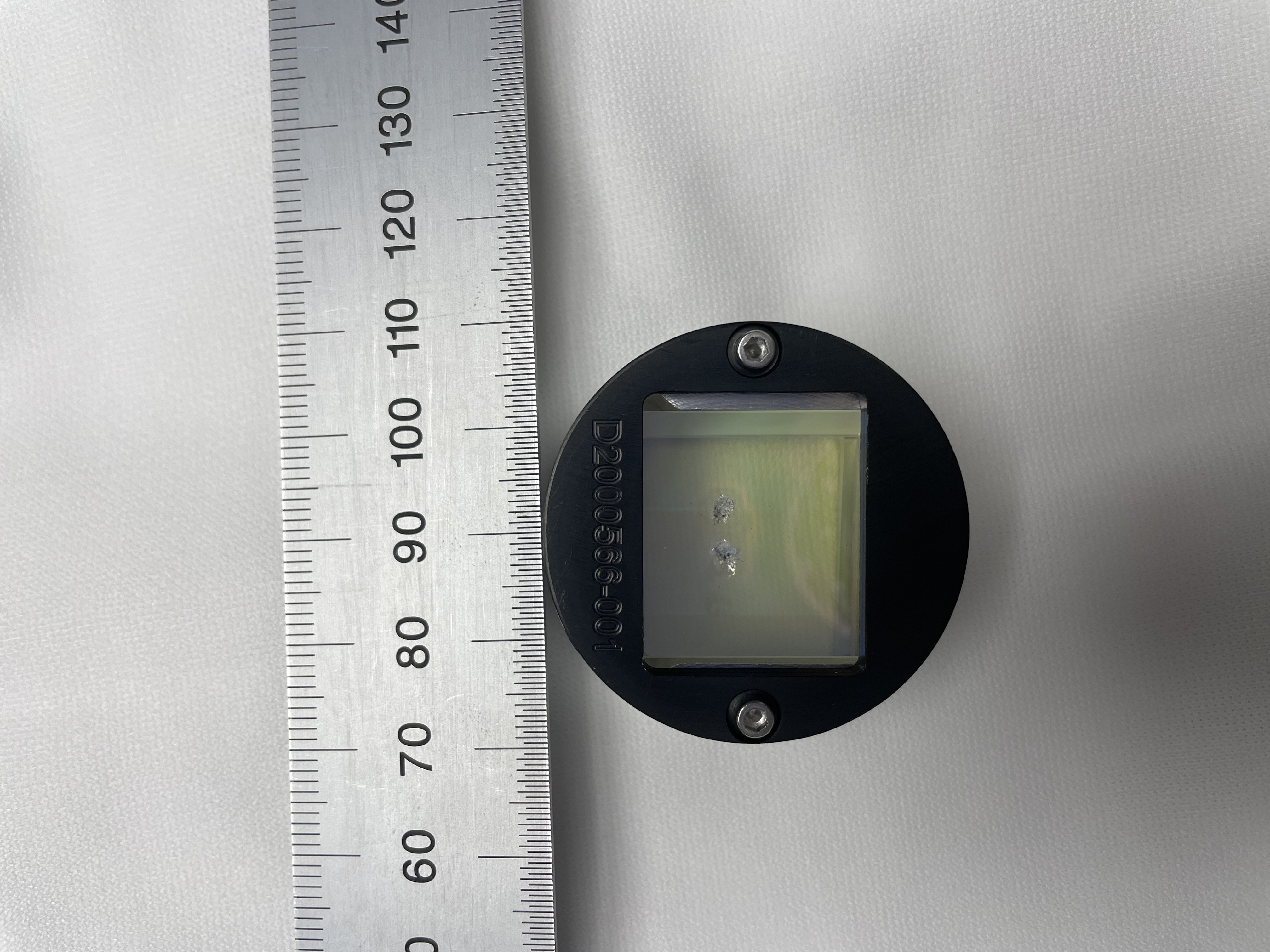
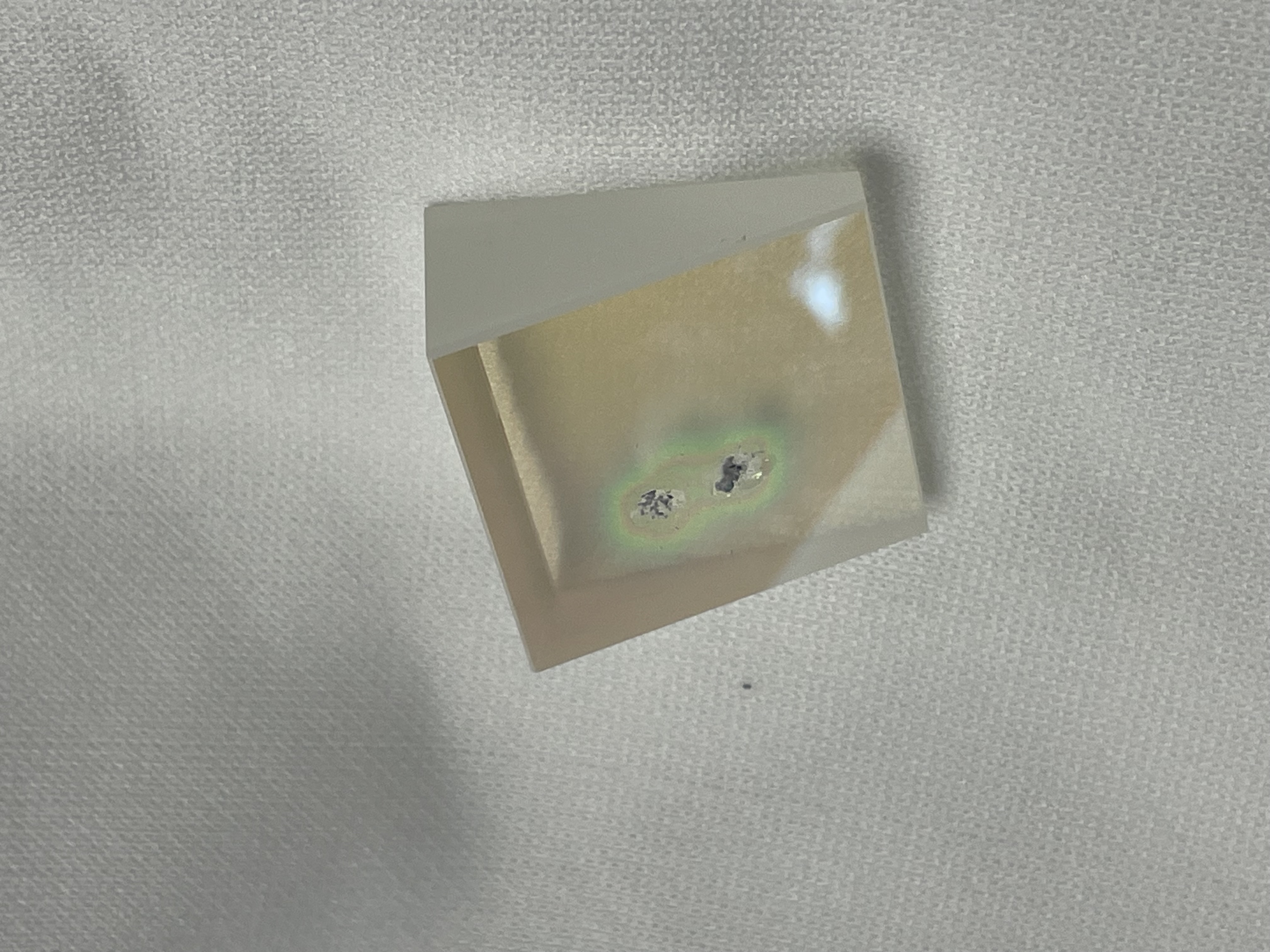
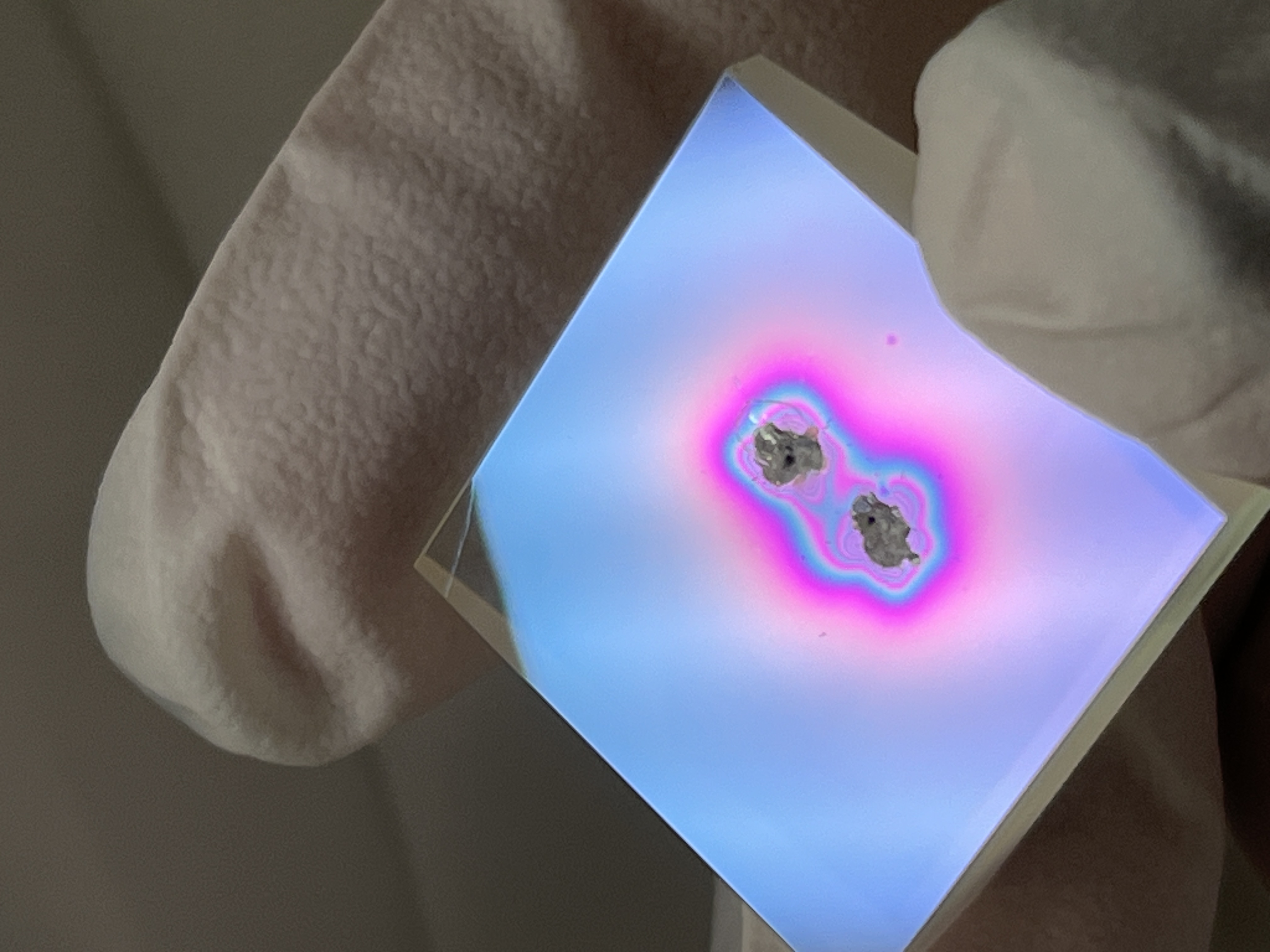
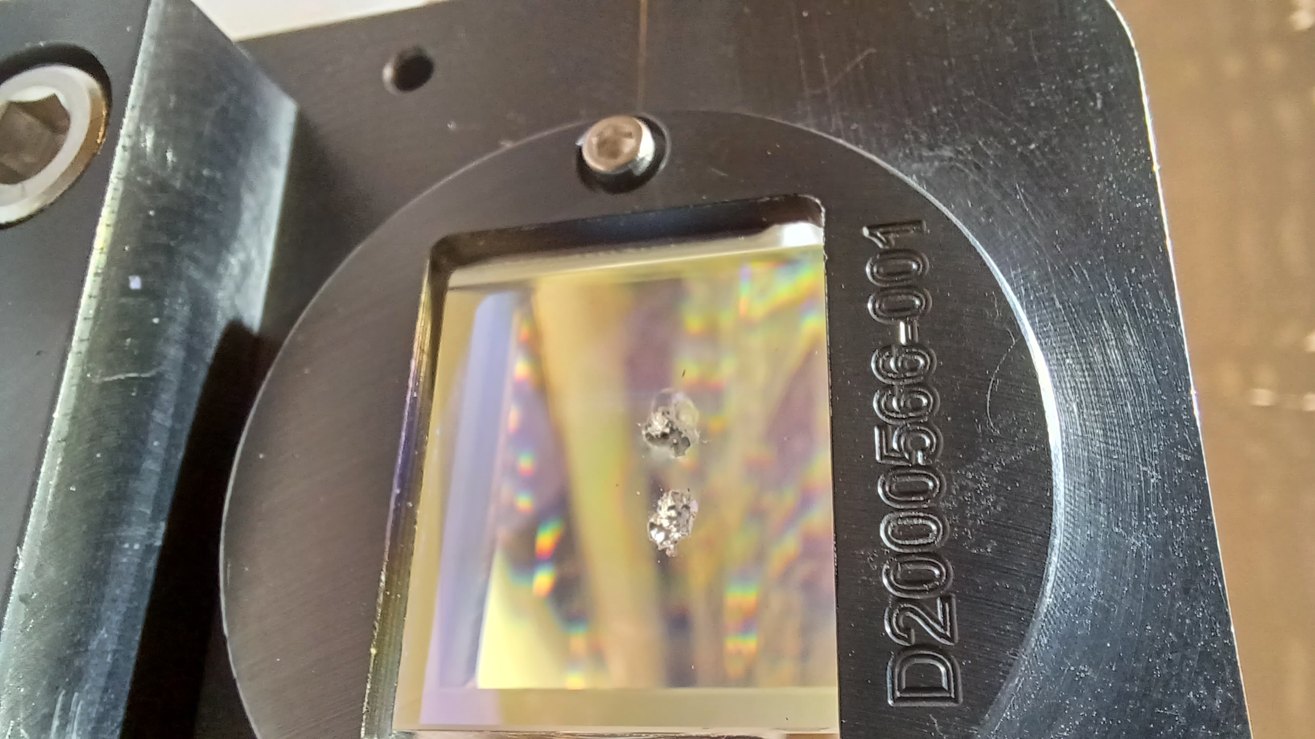
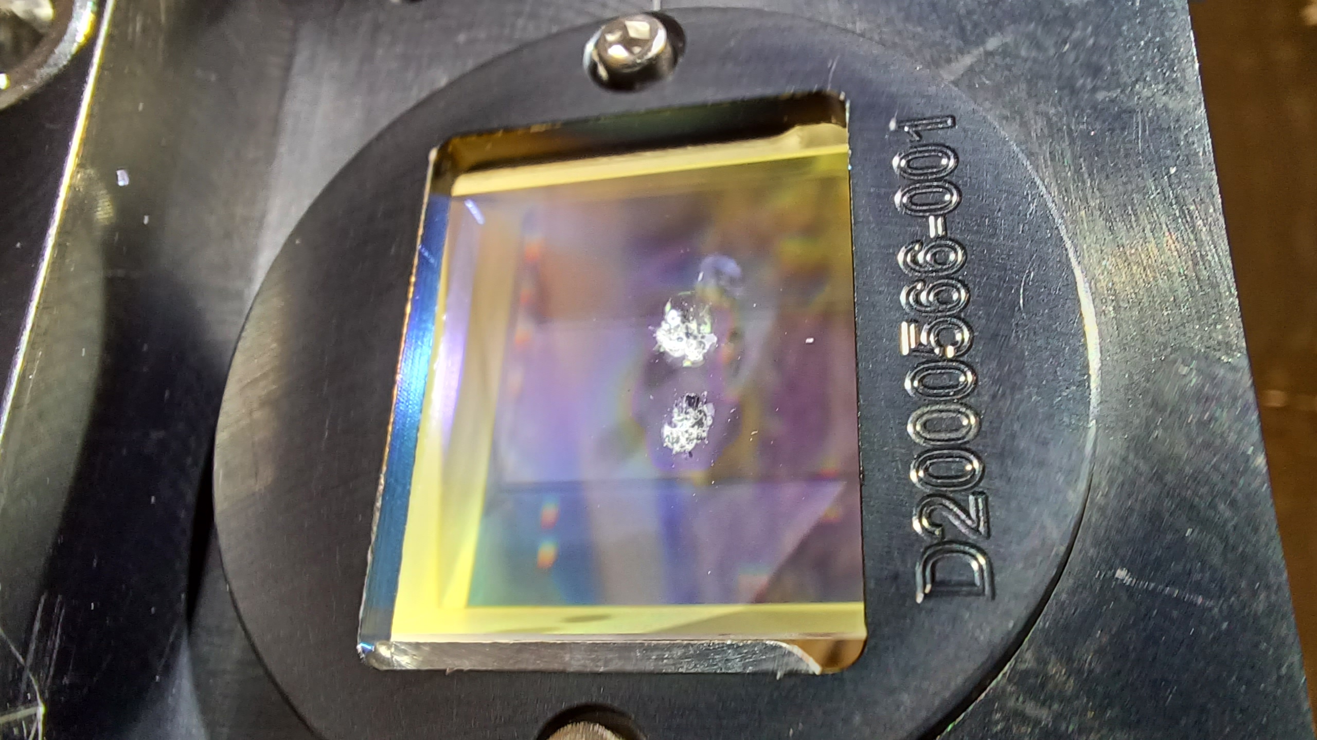
With the original KTP in place, the AR reflection isn't parallel to the table it is pitched up by 10/(530 +405 mm) about 11 mrad. The optic lab beam is hitting the KTP a little below the burned spot, which would have been on the +X side in chamber. The burned spots are on the side closer to our alignment laser.
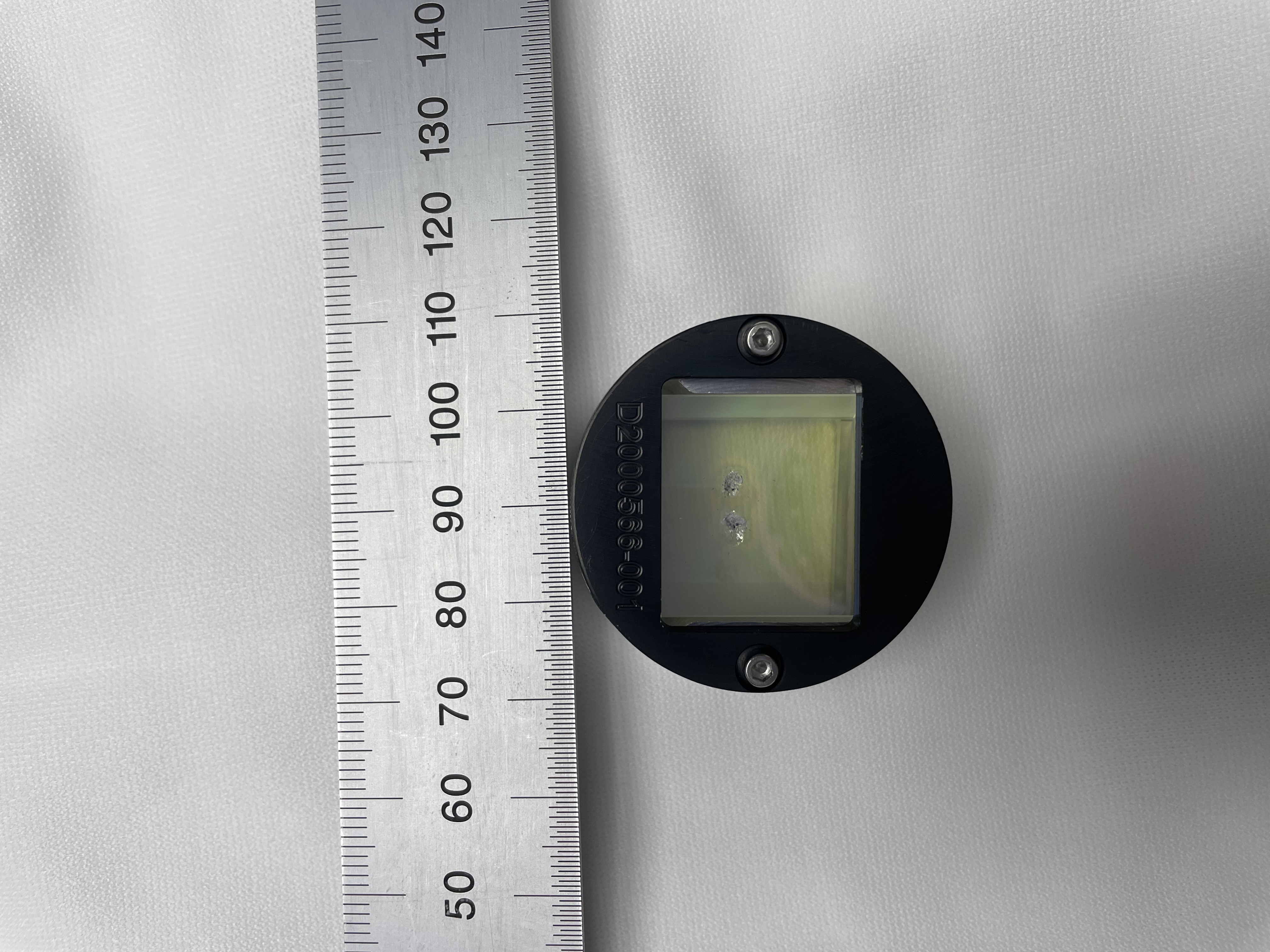
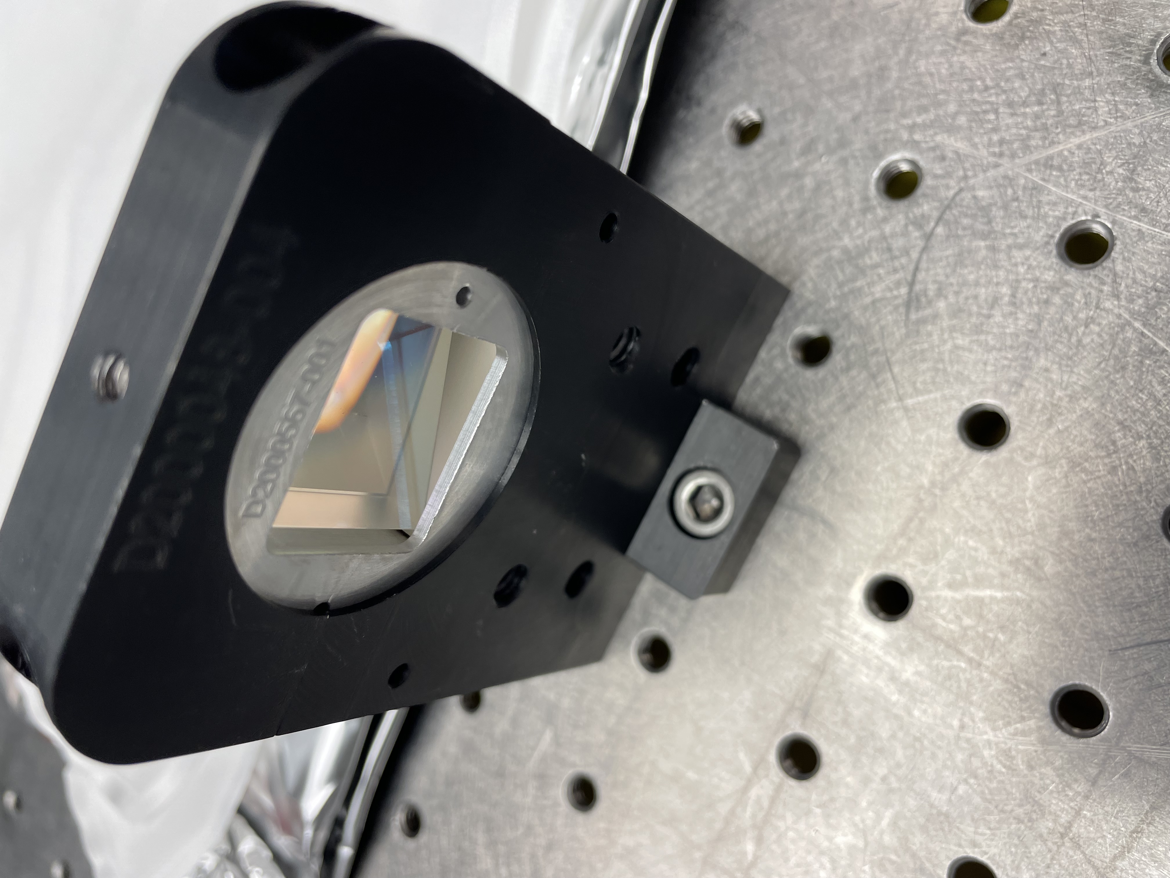
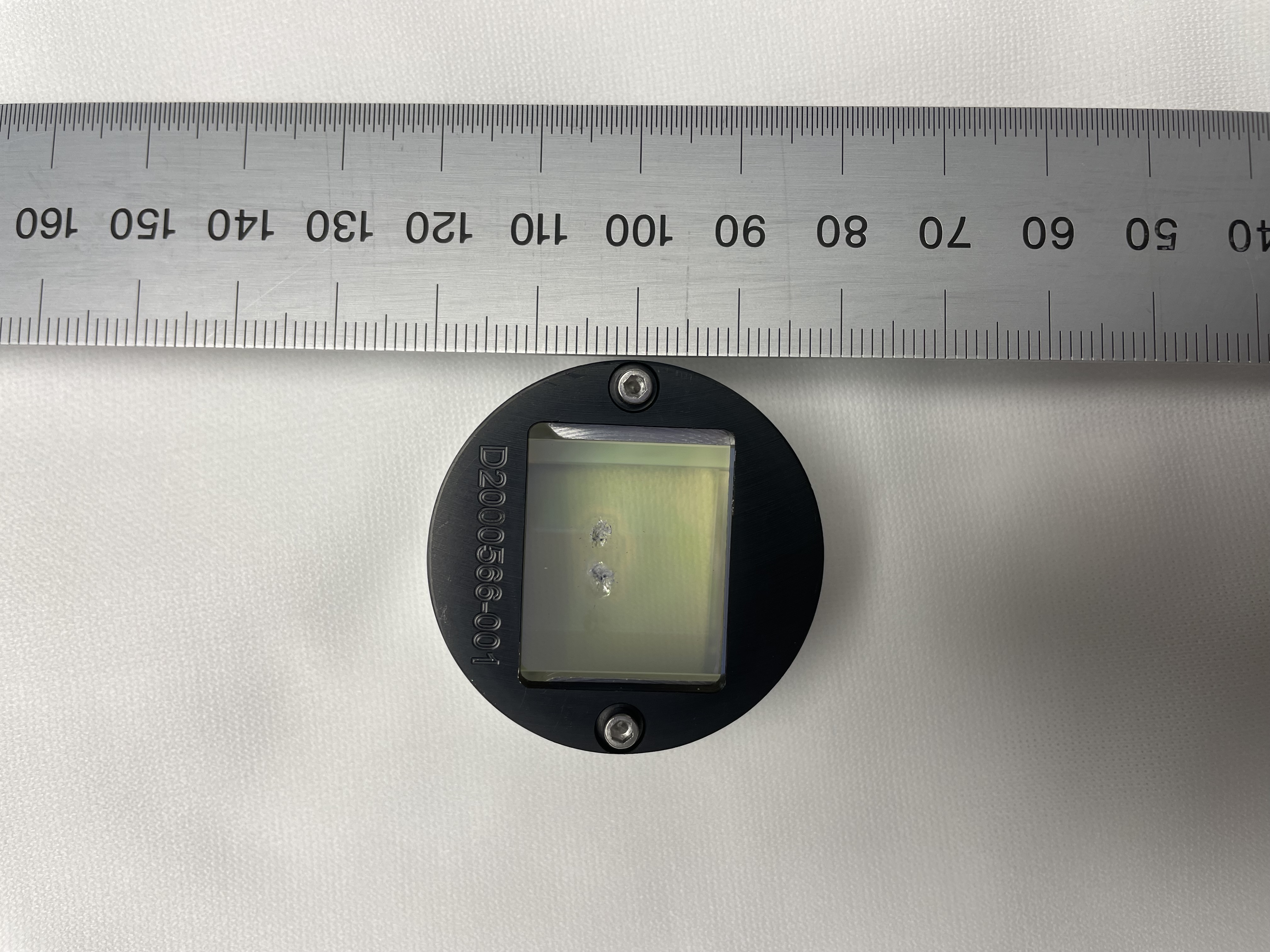
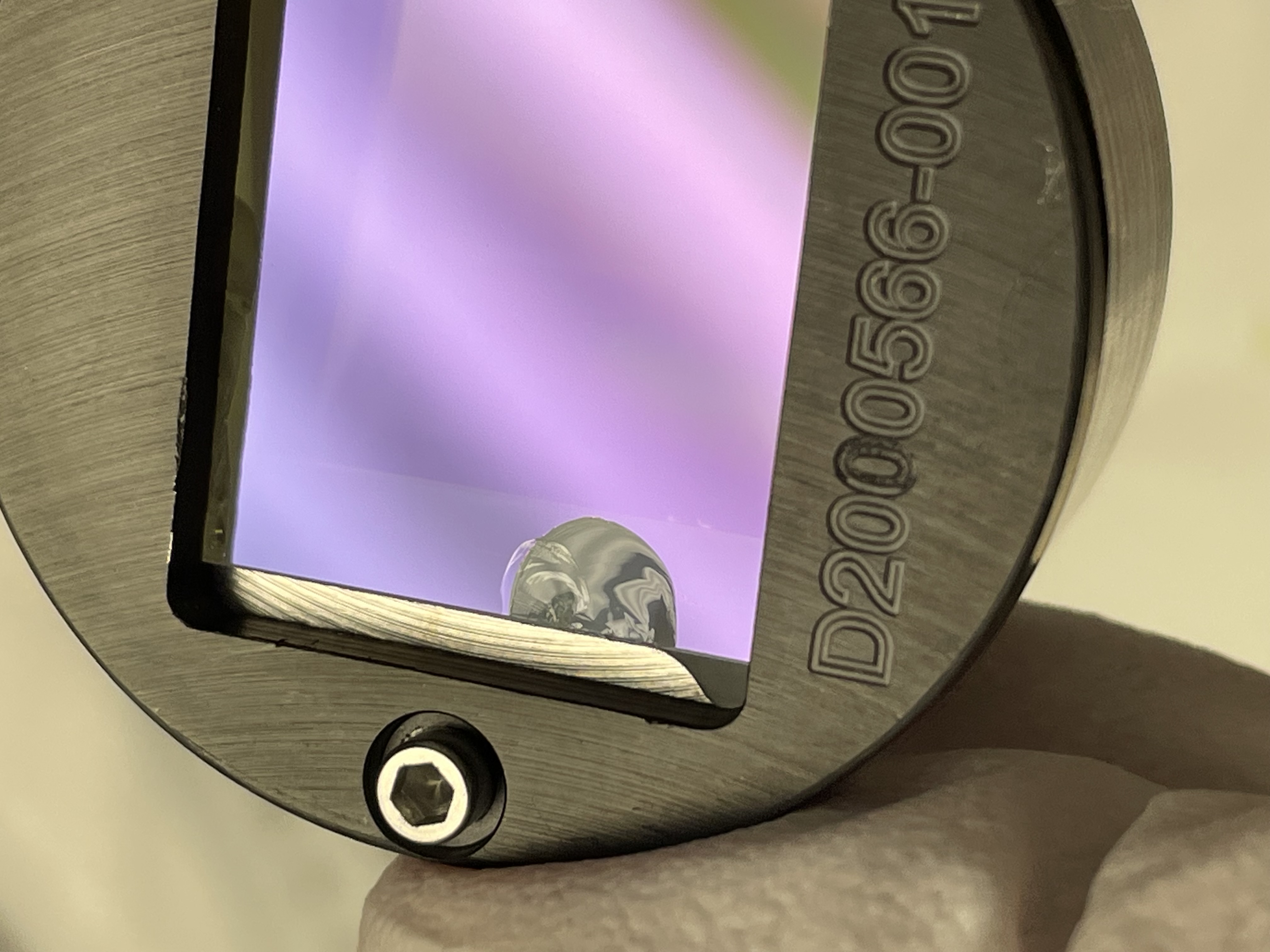
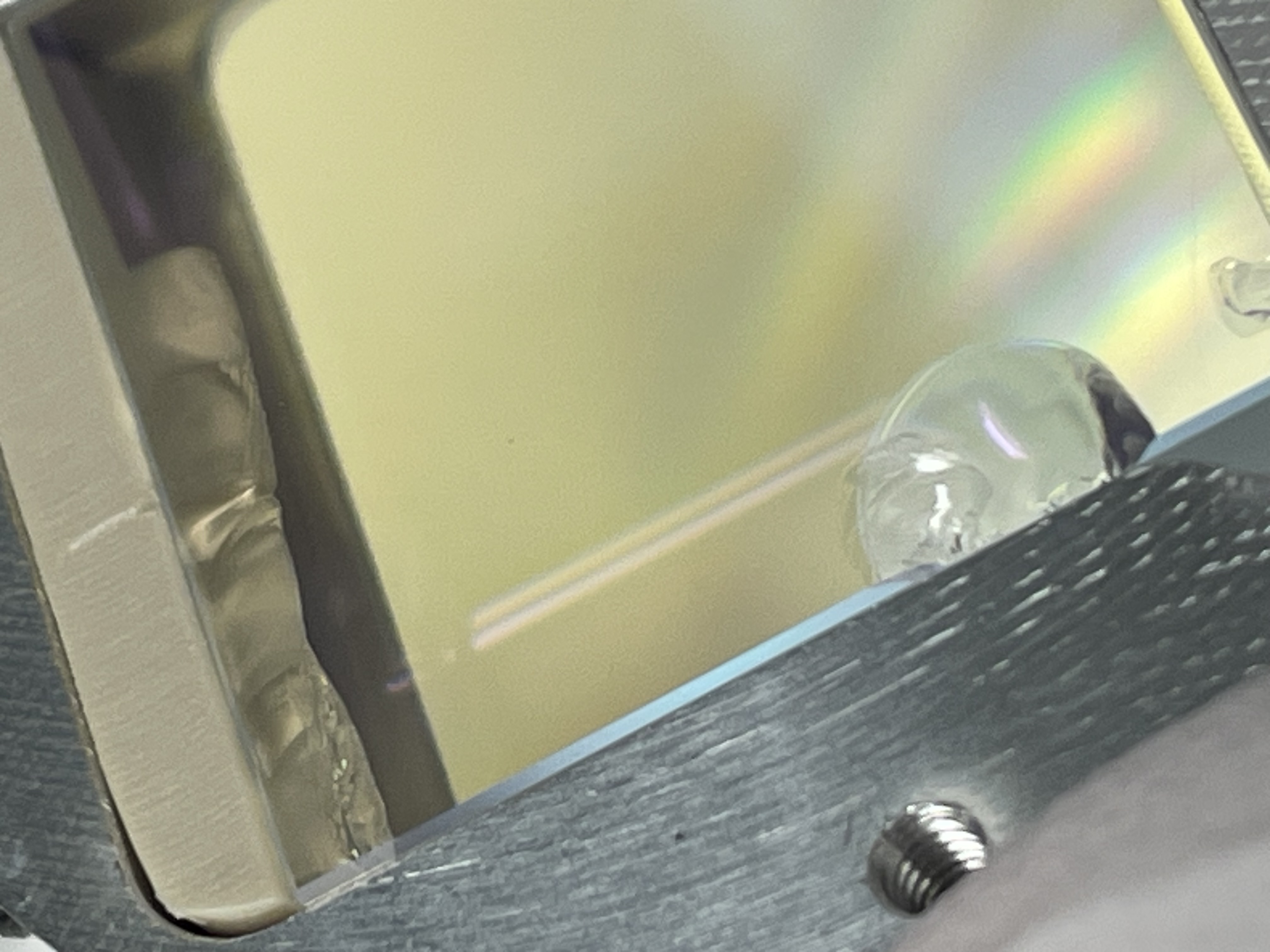
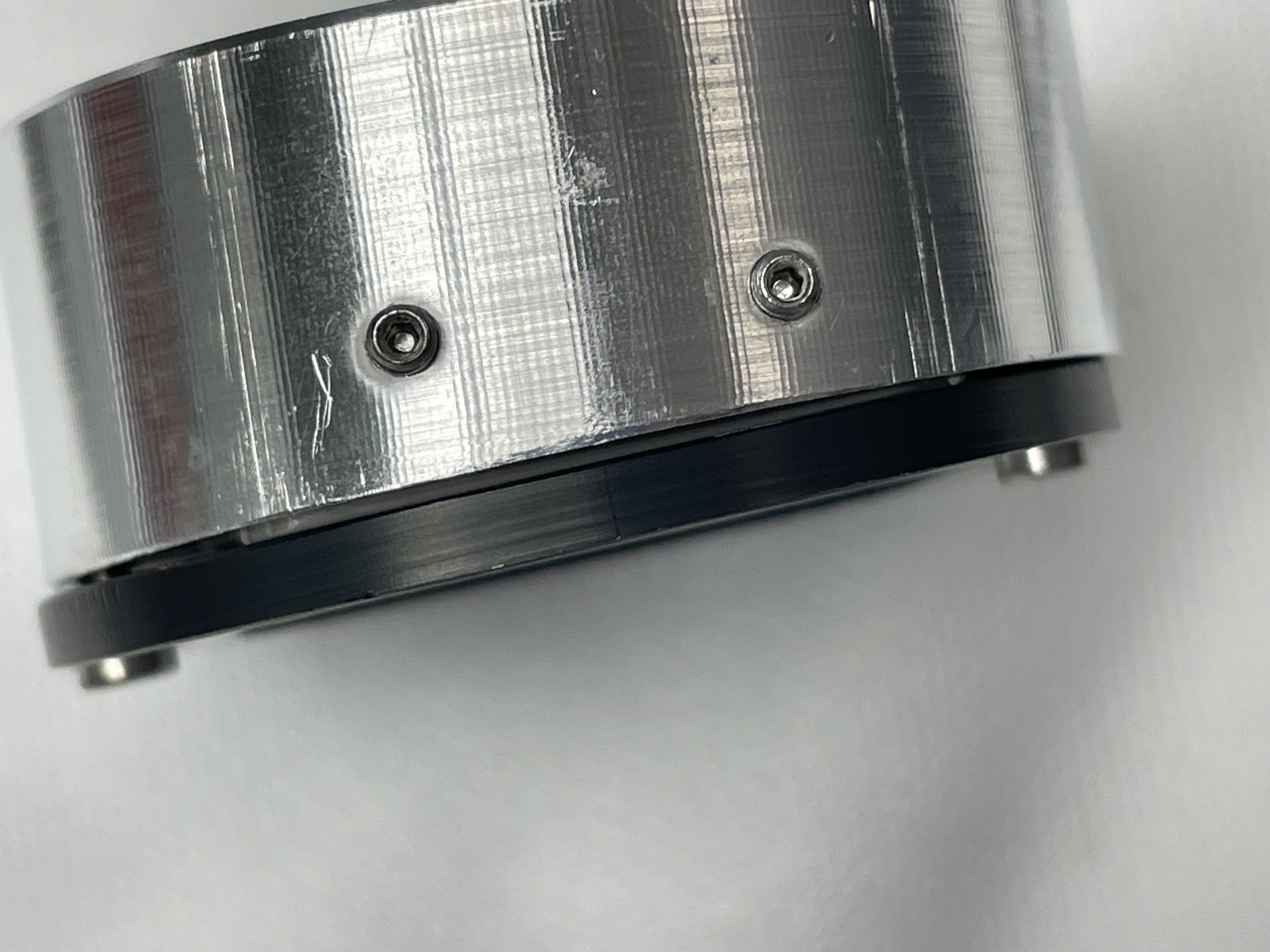
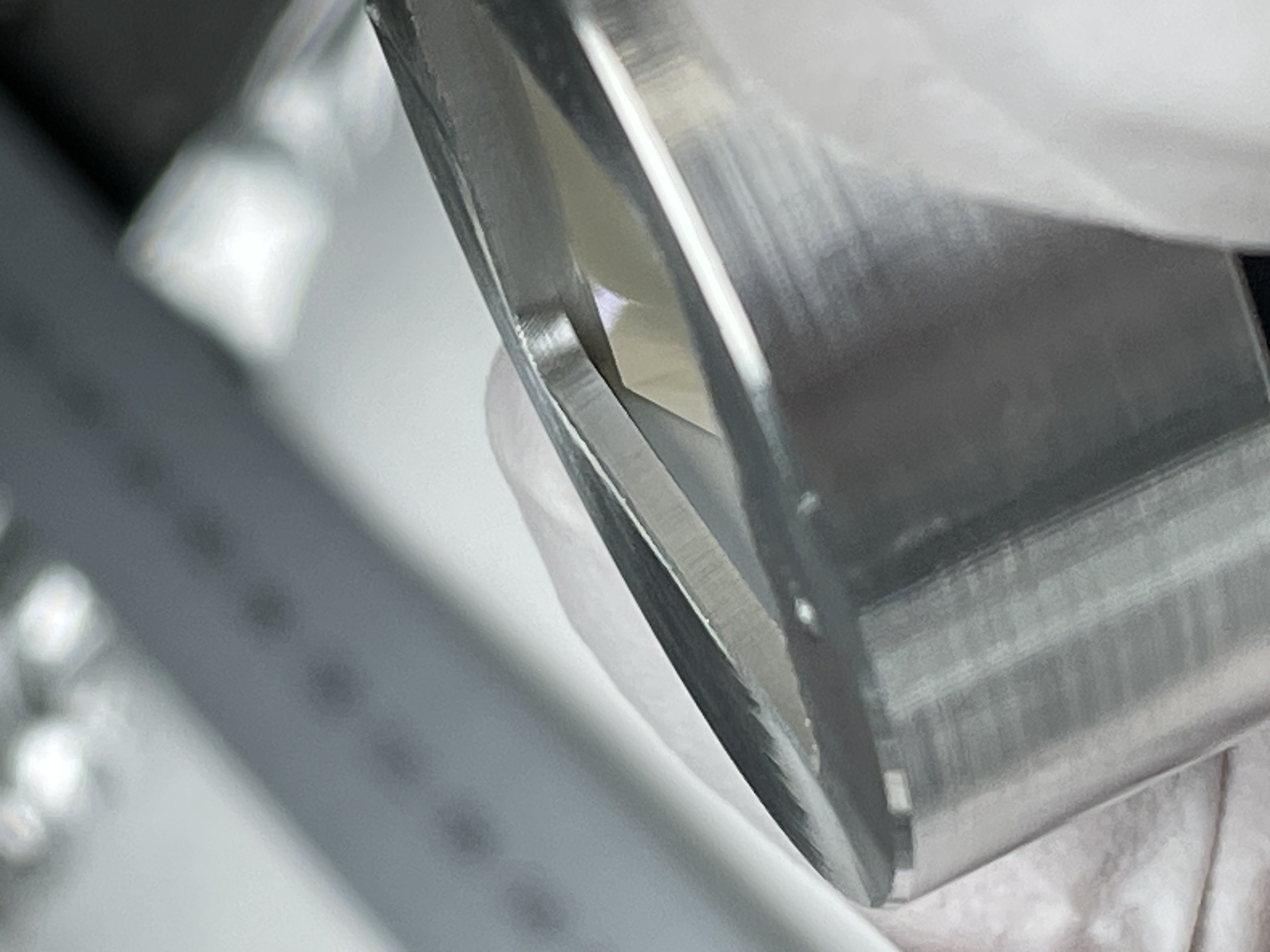
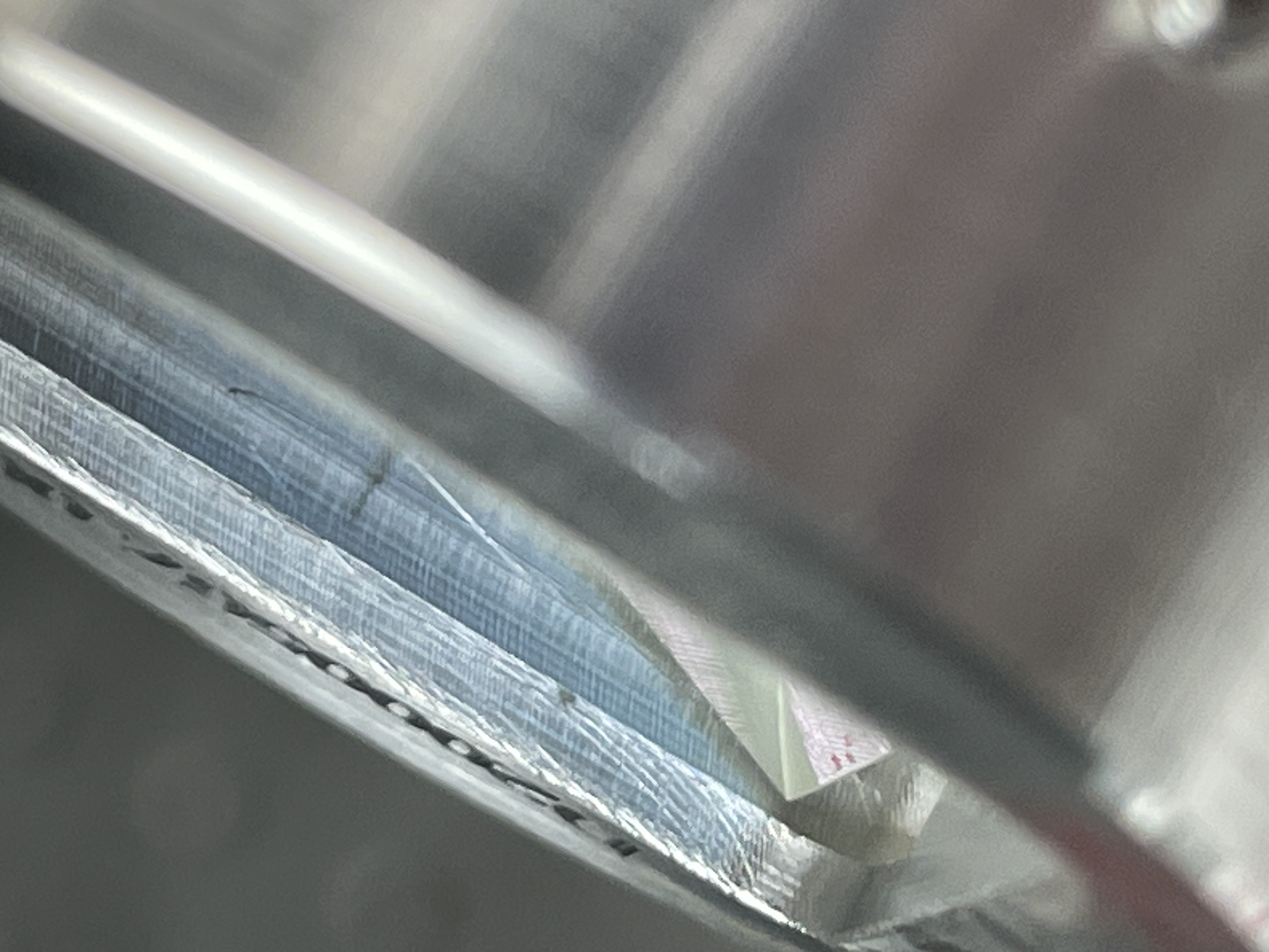
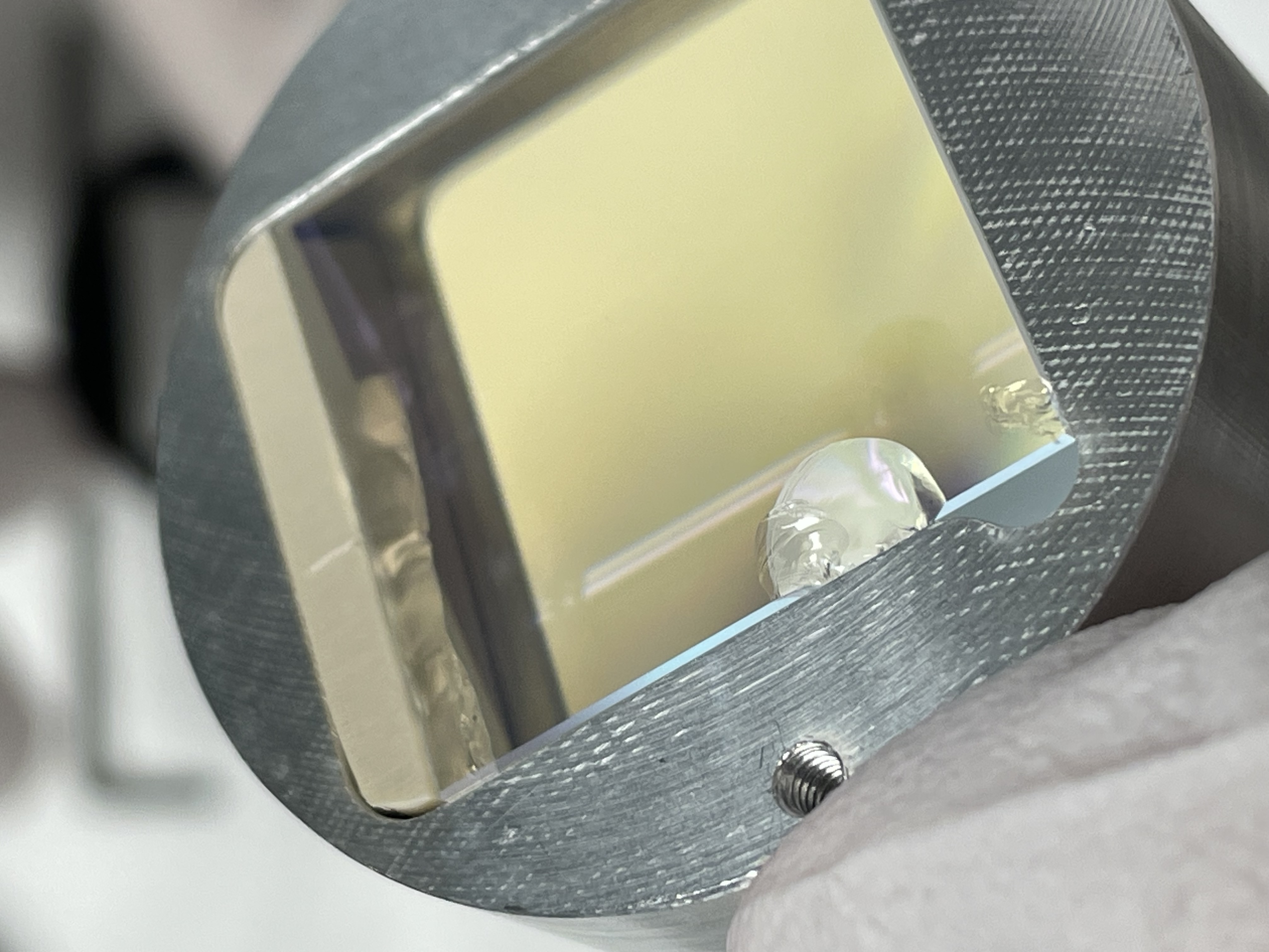
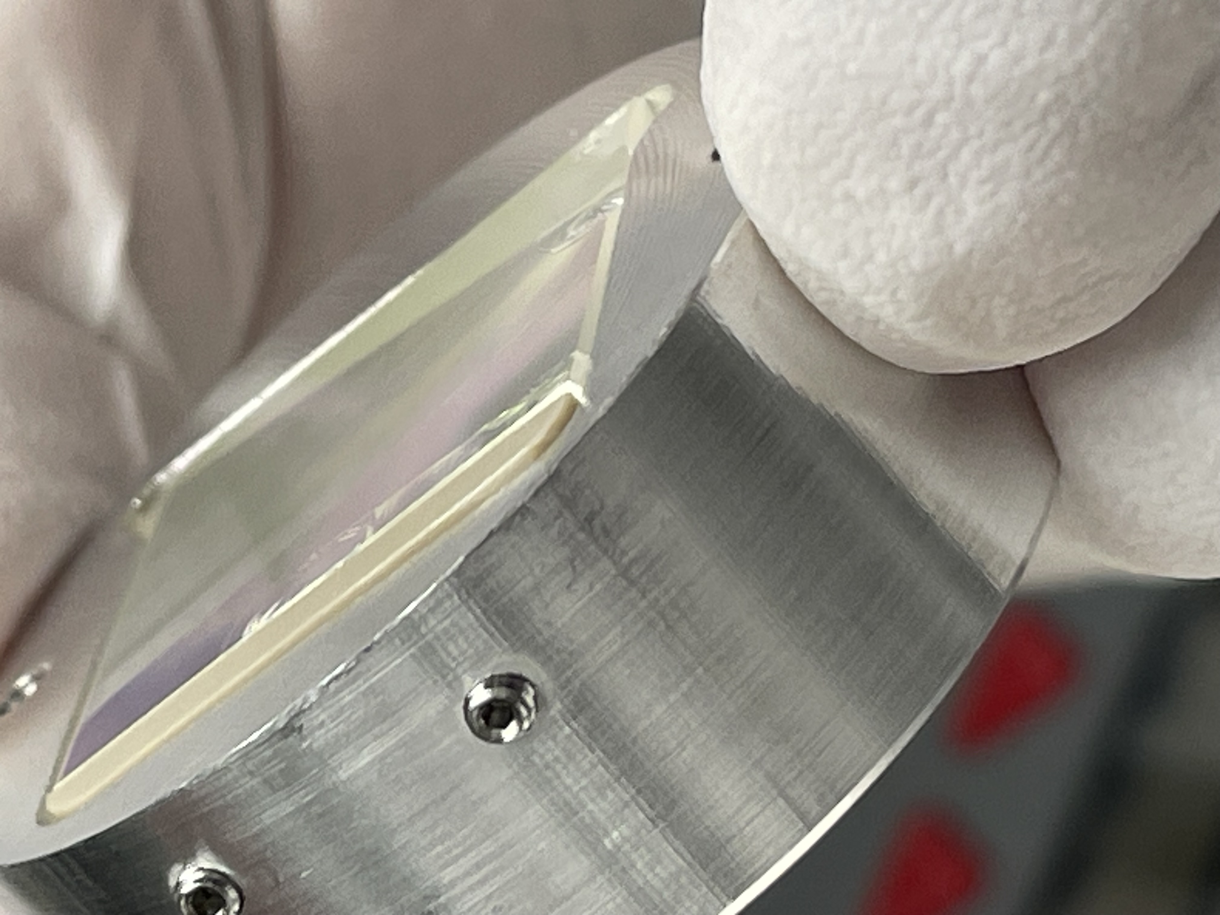
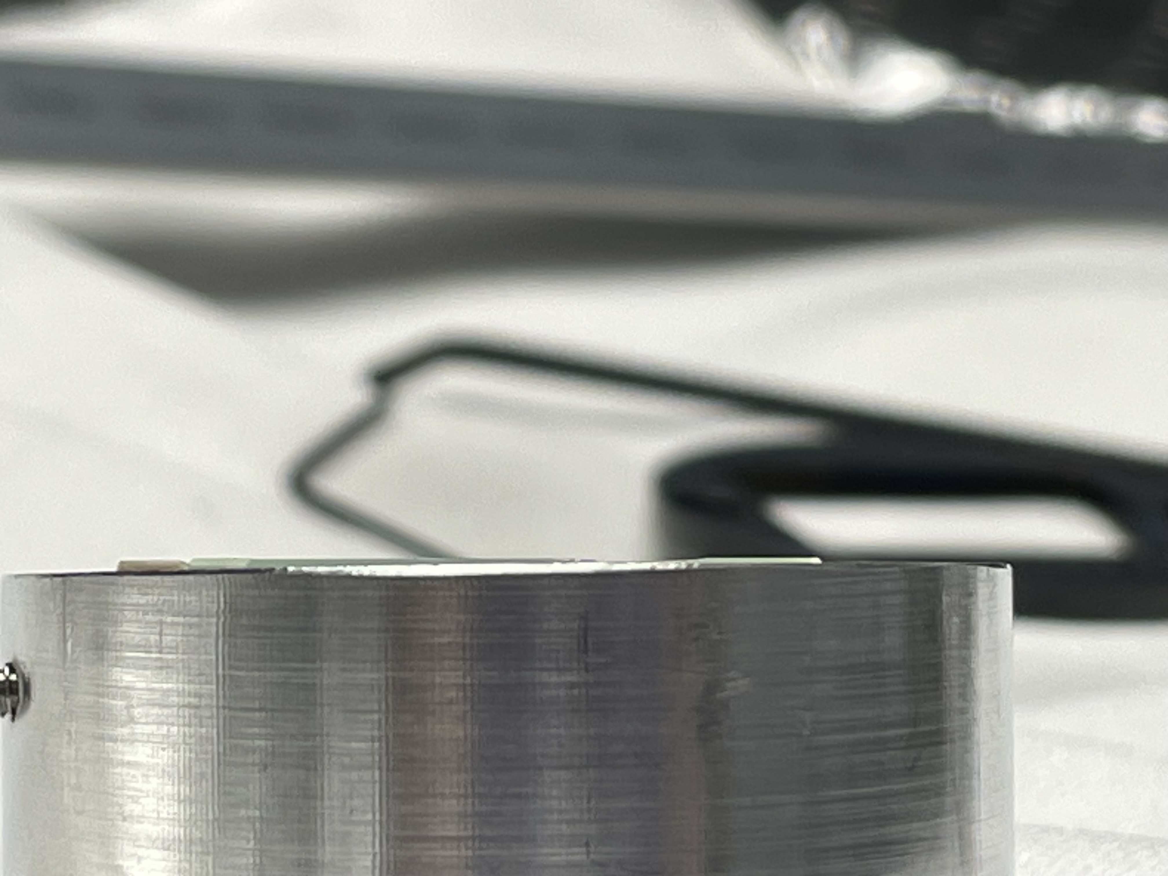
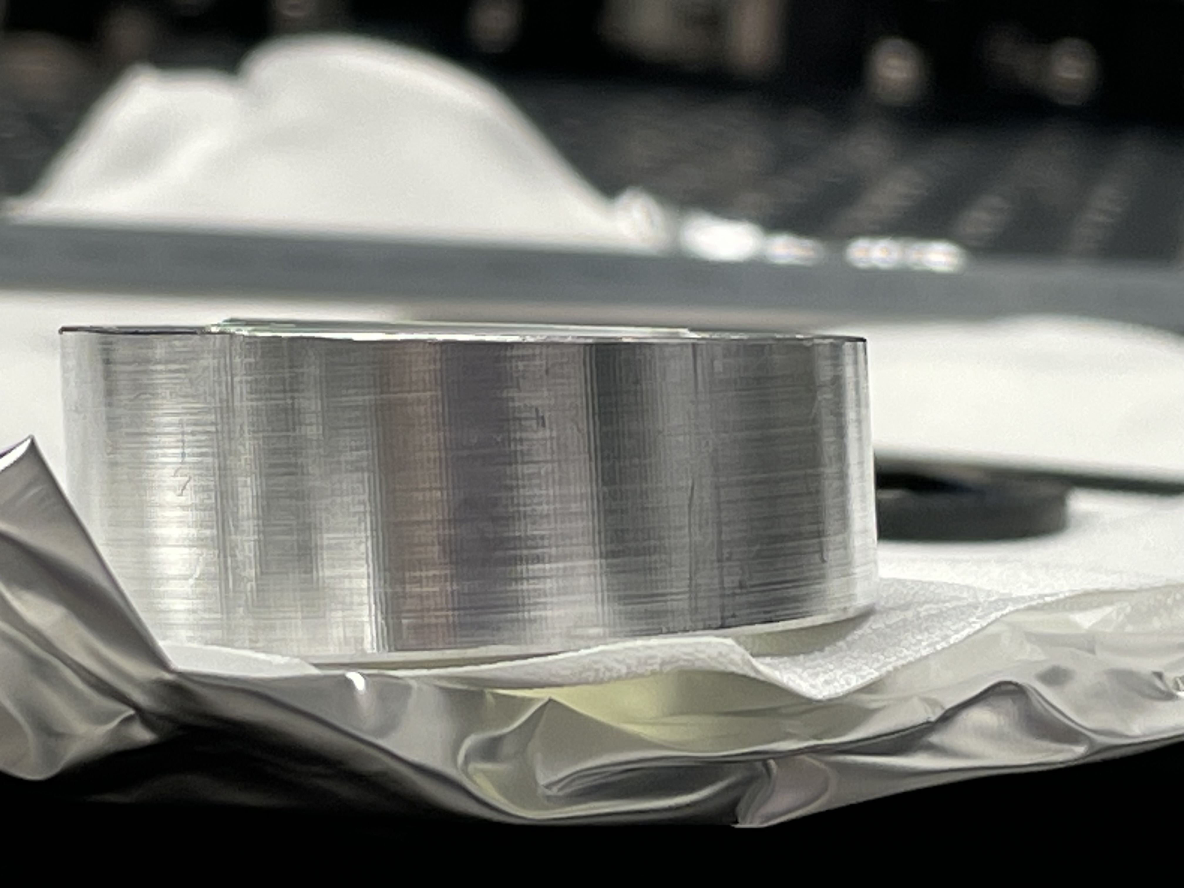
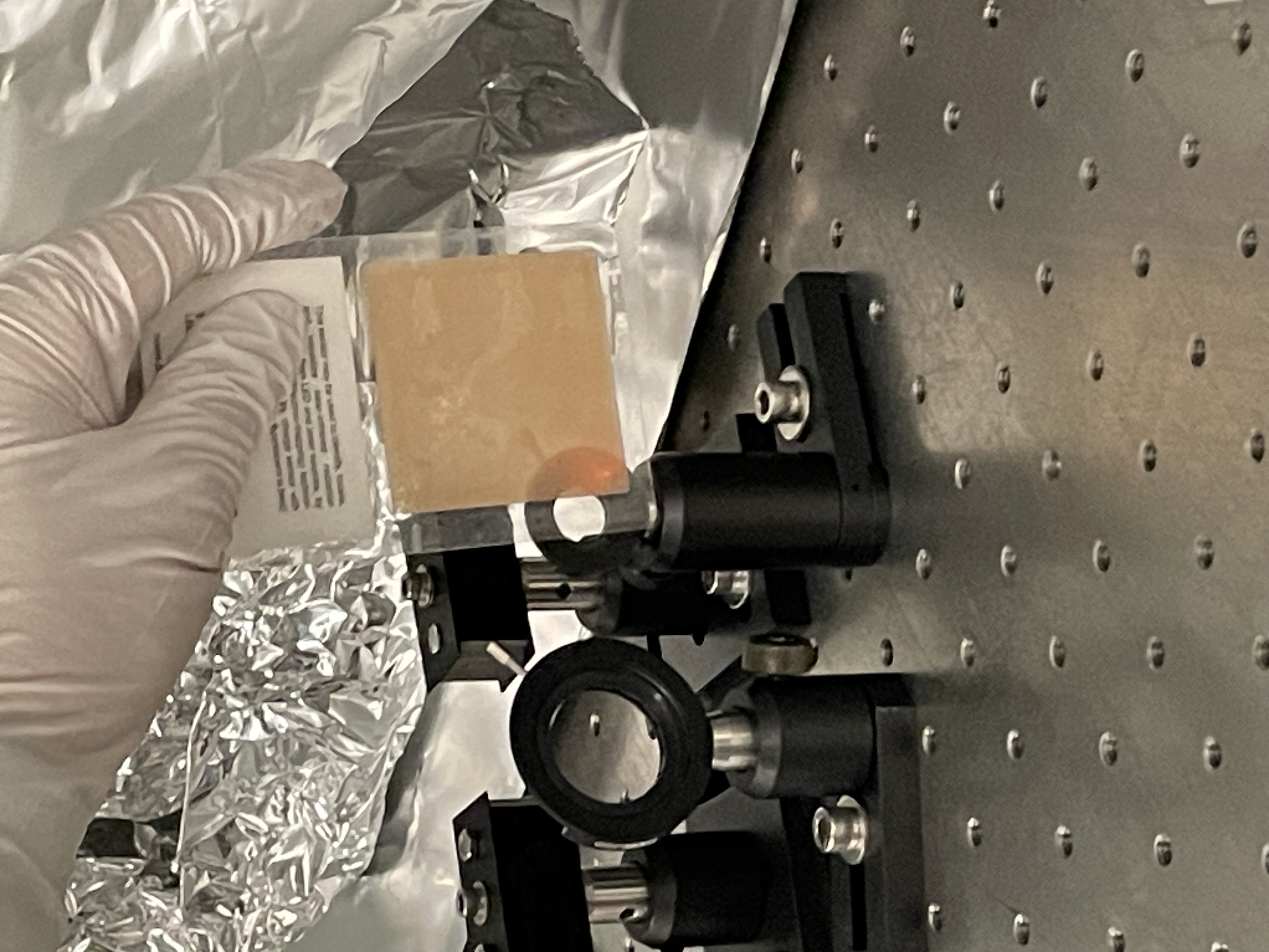
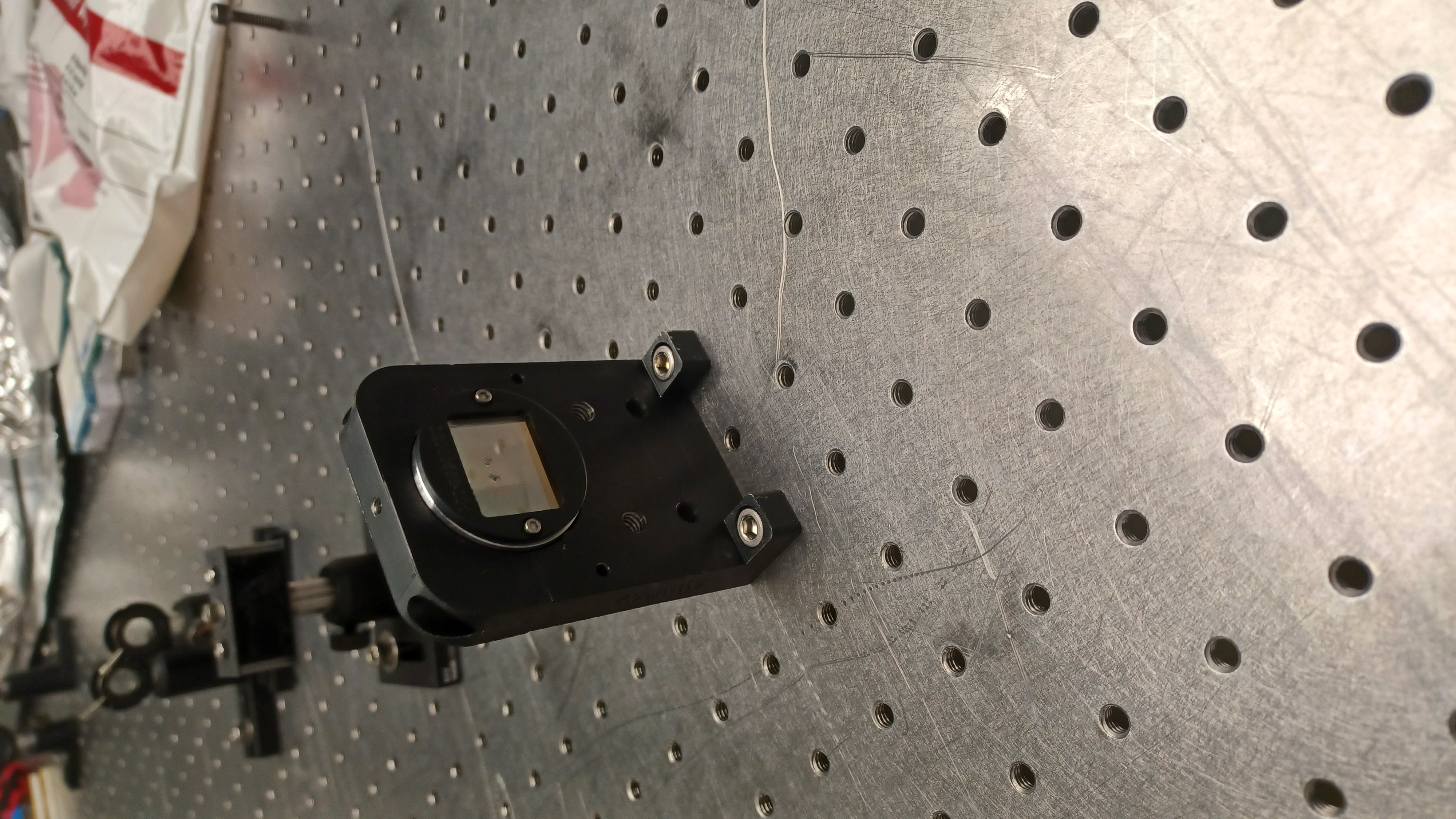
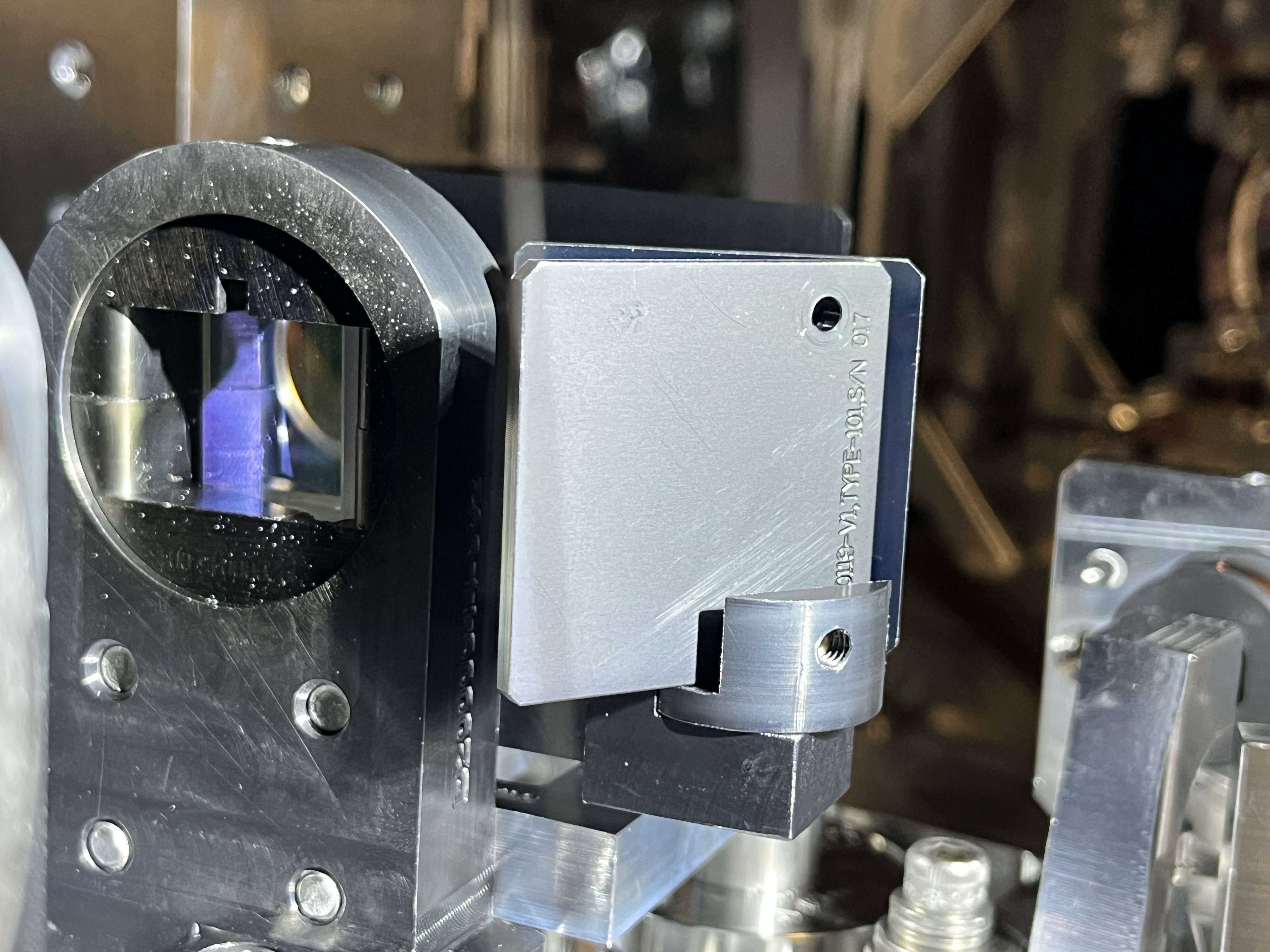
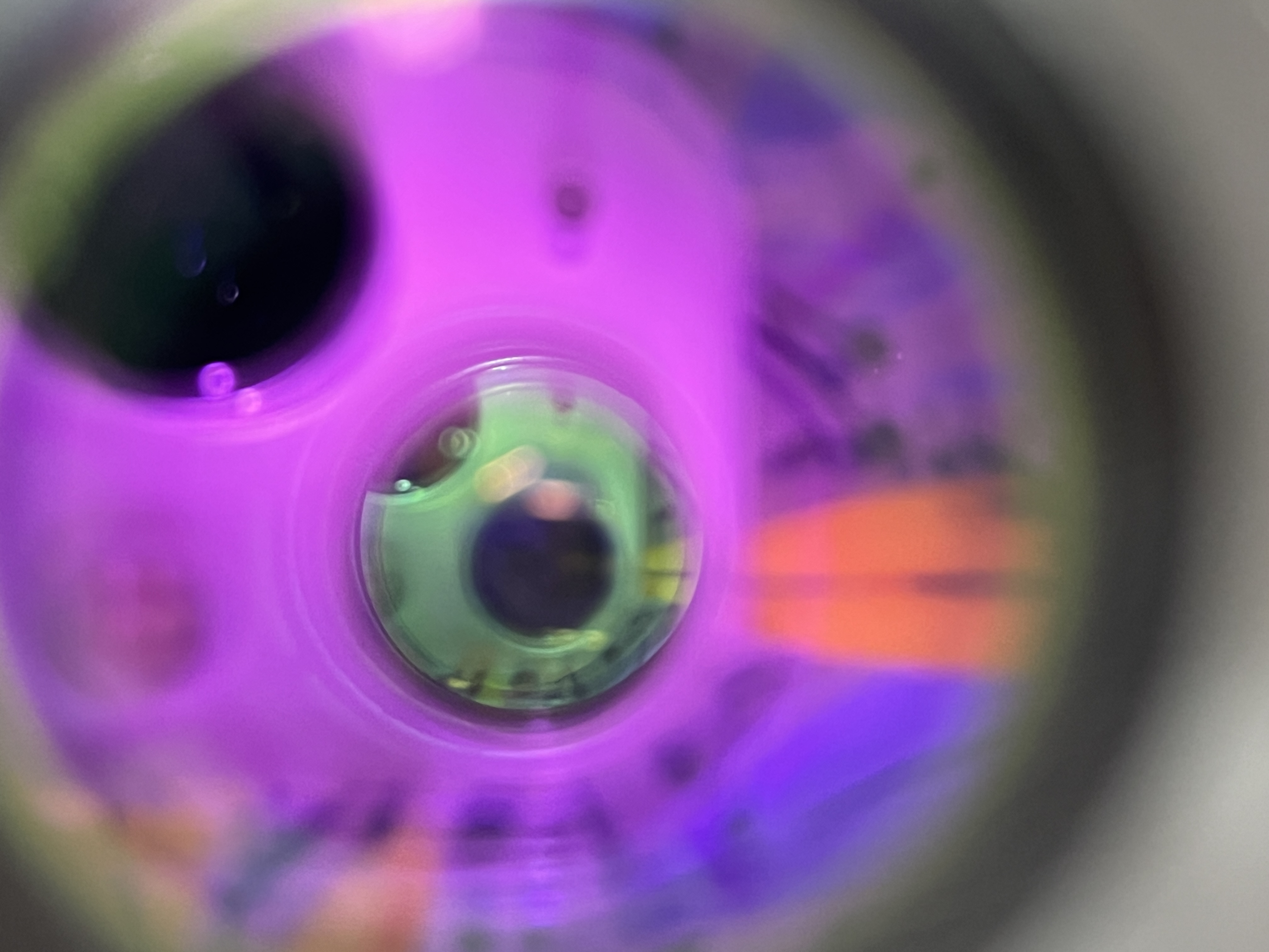
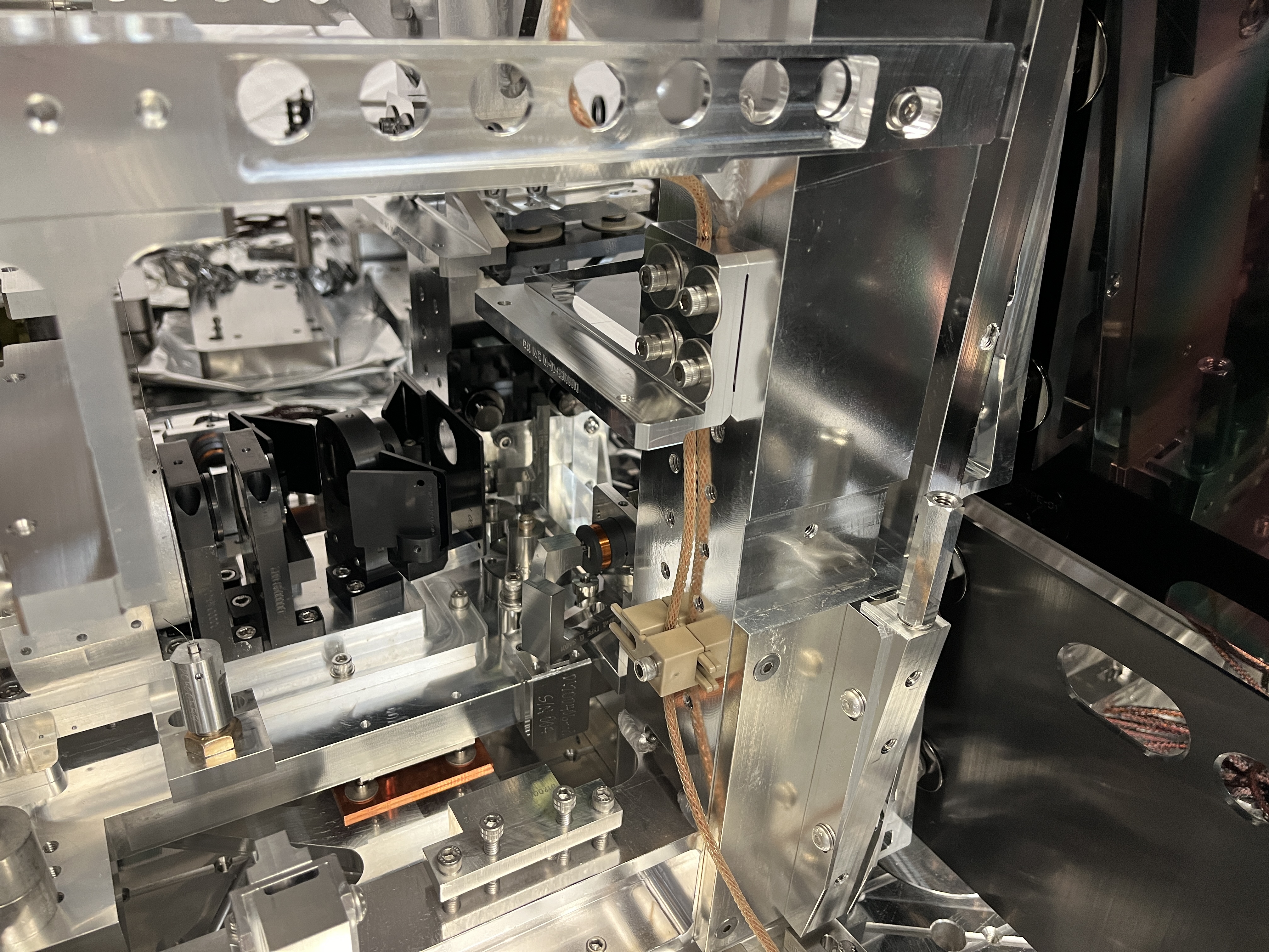
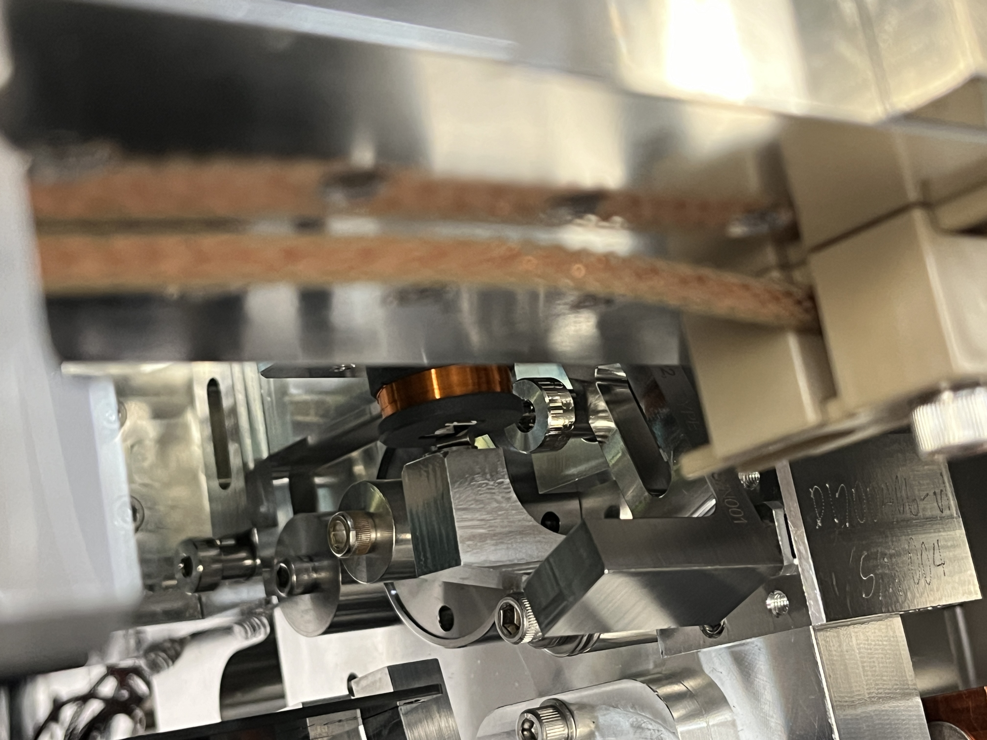
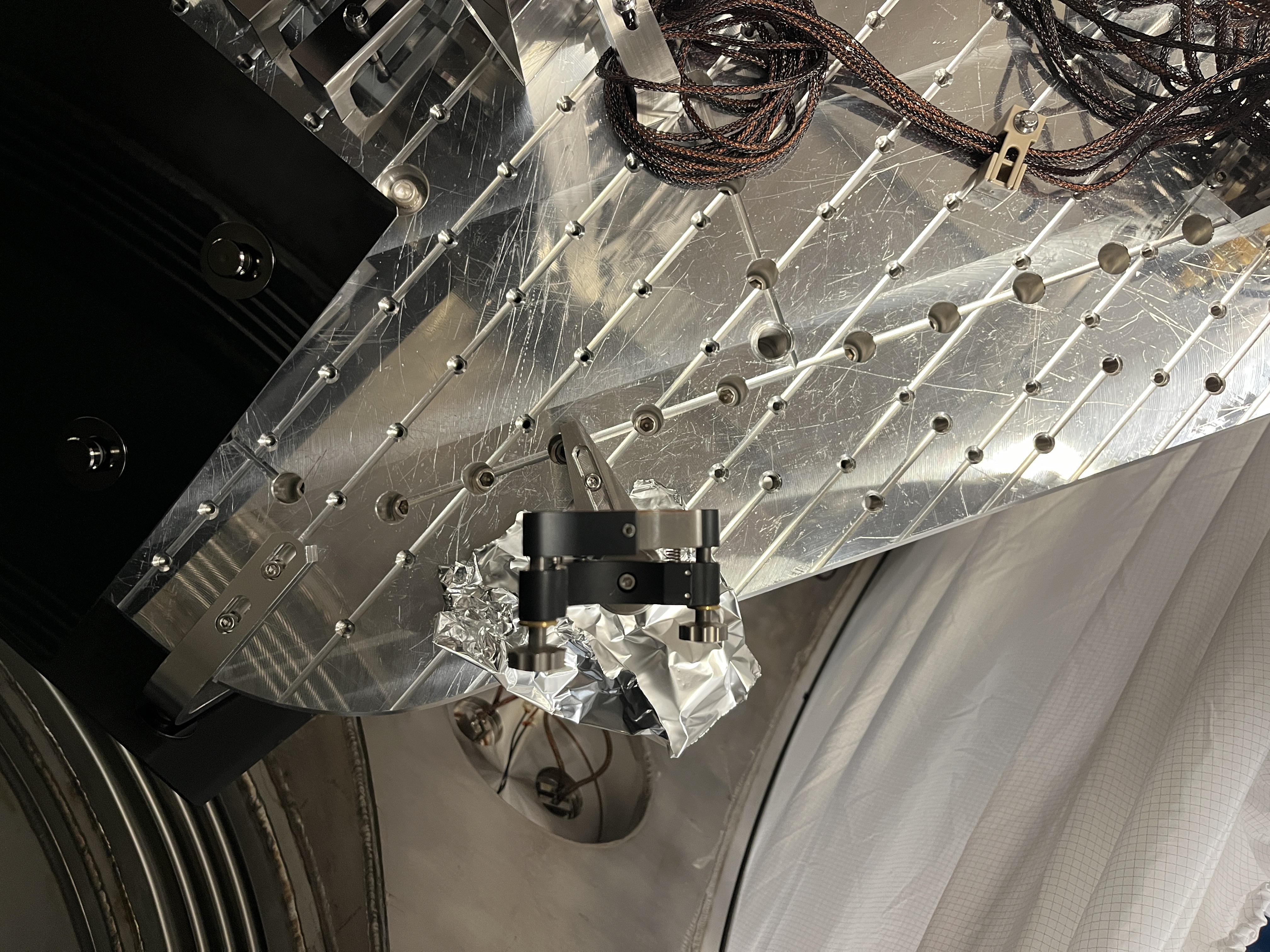
Before taking it out of the mount we took a variety of photos showing the damage spots position. We did not find any indium foil in the mount, Paul had warned us that there might be indium between part 5 and part 9 of D2000038.
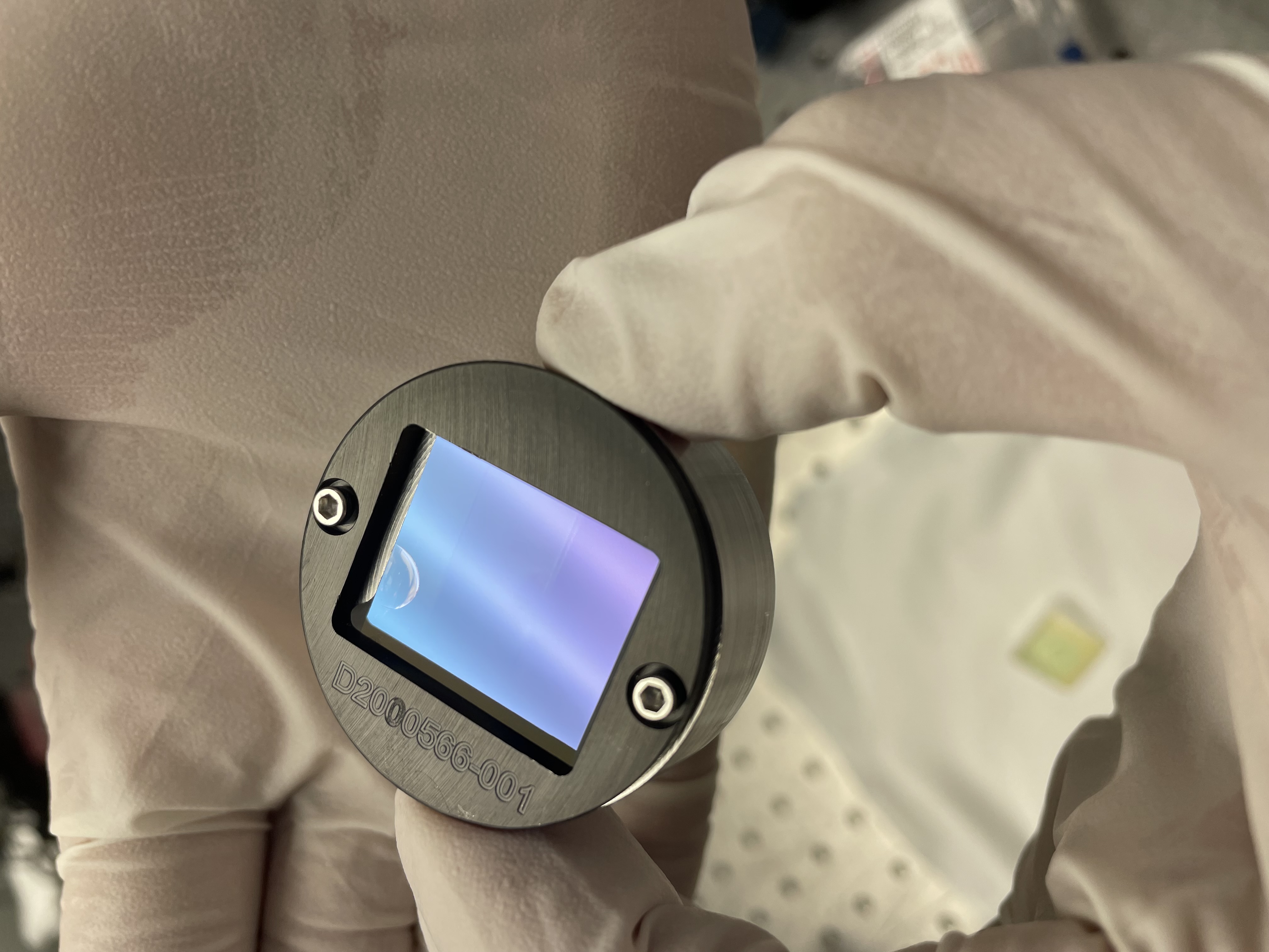
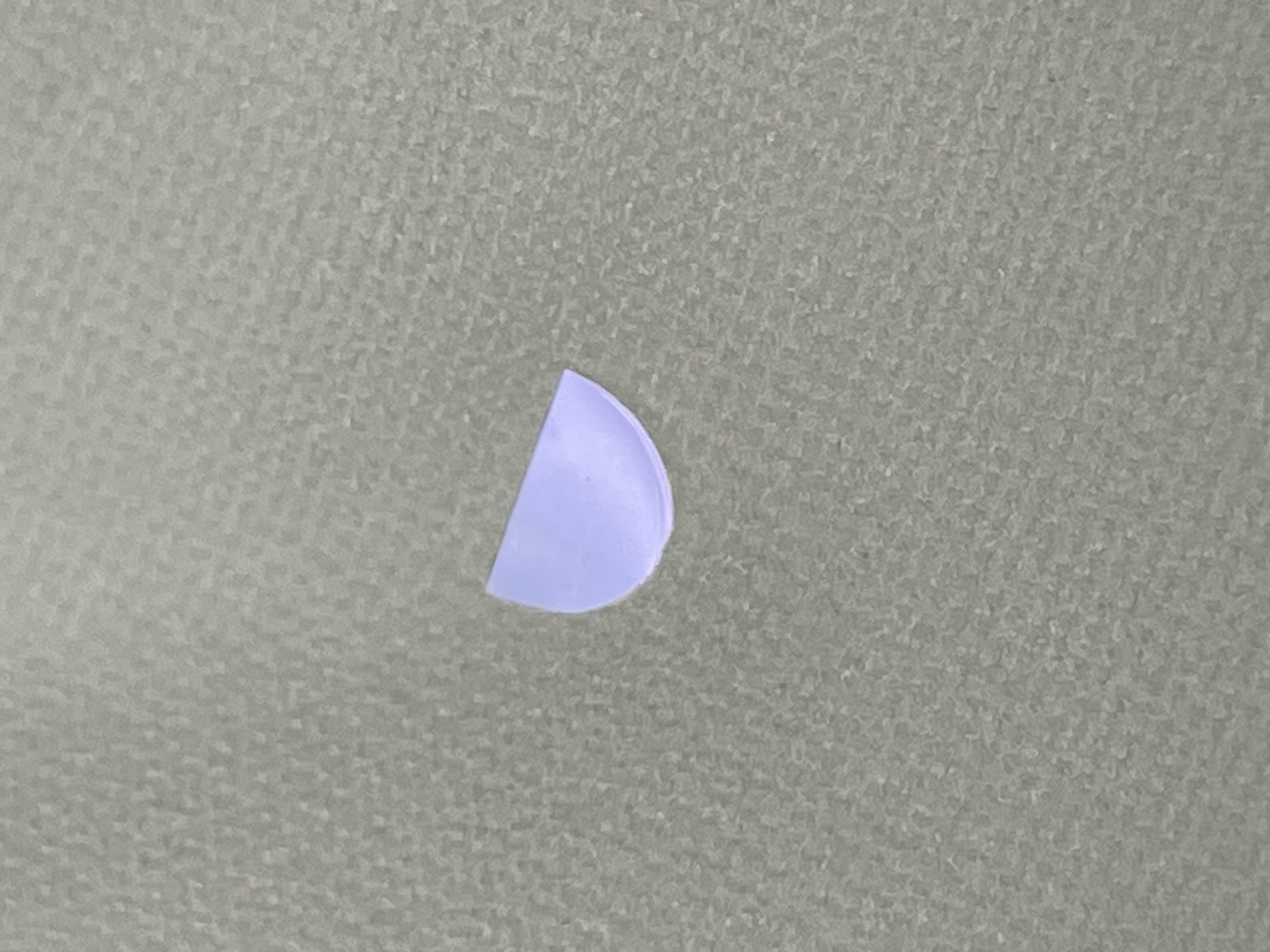
As we were placing the new crystal in the mount, we left the set screws (11) that hold the peek loose, and held the piece upsidedown while we screwed in the bolts labeled #10 to hold on the aliuminum plate. It chipped as we were tightening the bolts labeled 10 in D2000038. After some discussion with Rodica, Paul, Gabriele, we went back to the lab to take photos of the chip and try to understand how the chip happened. We have photos showing that the crystal was proud of the top of part 5, the orientation of the black metal piece. After we removed the black front plate, we could see that the KTP was firmly stuck in part #5, with the wedge stuck. Keita had to push on the back of the crystal to get it loose.
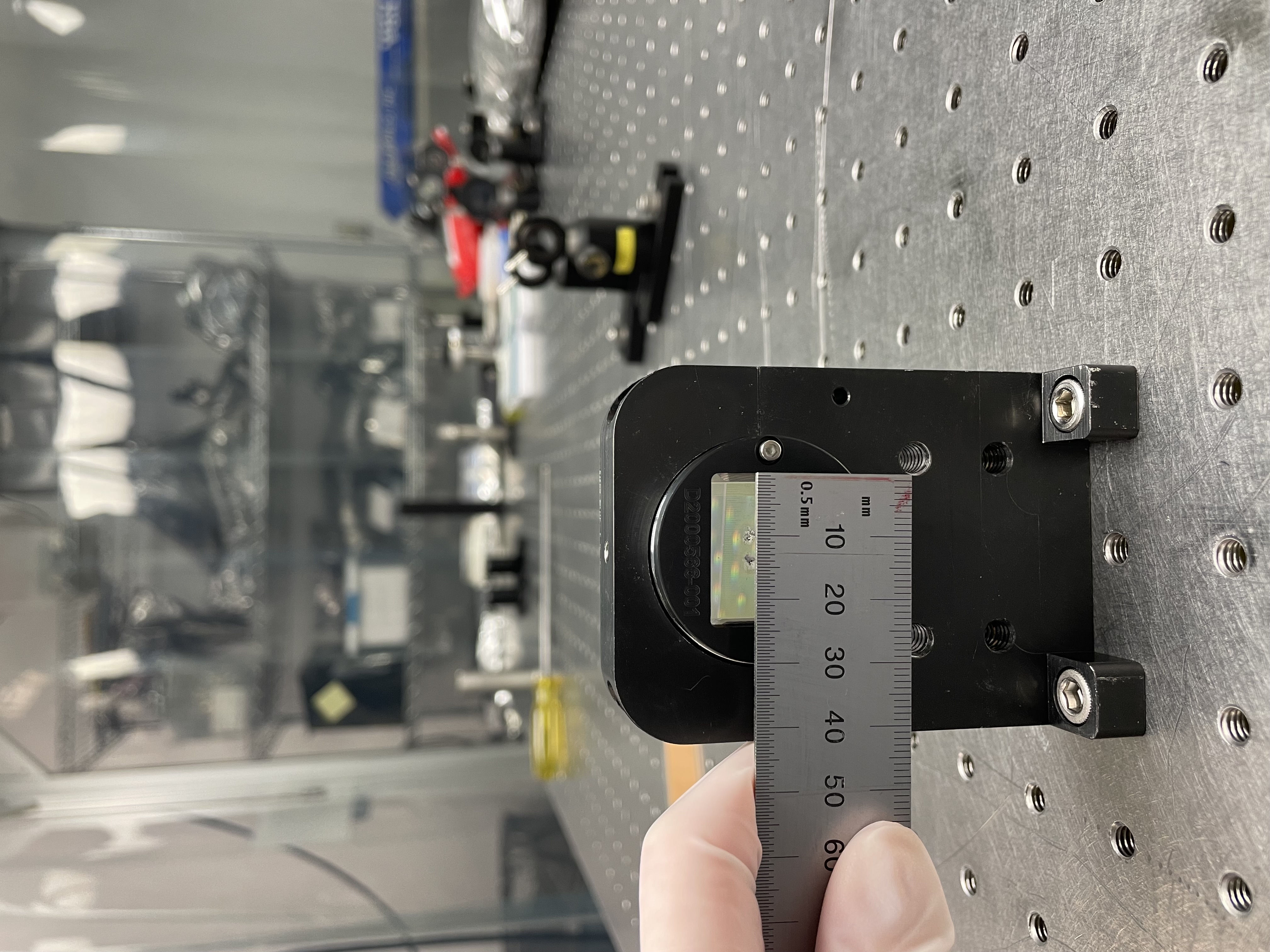
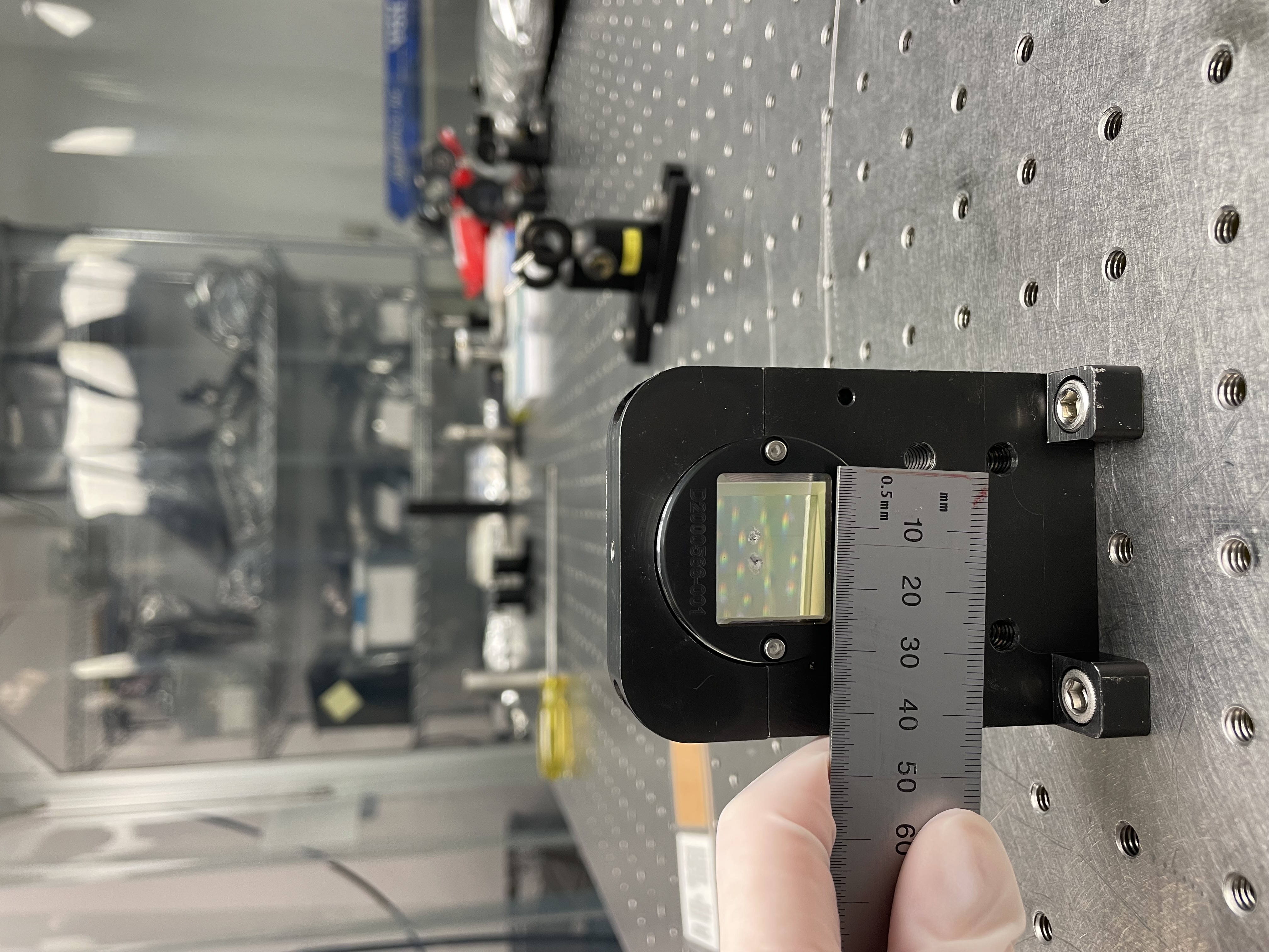
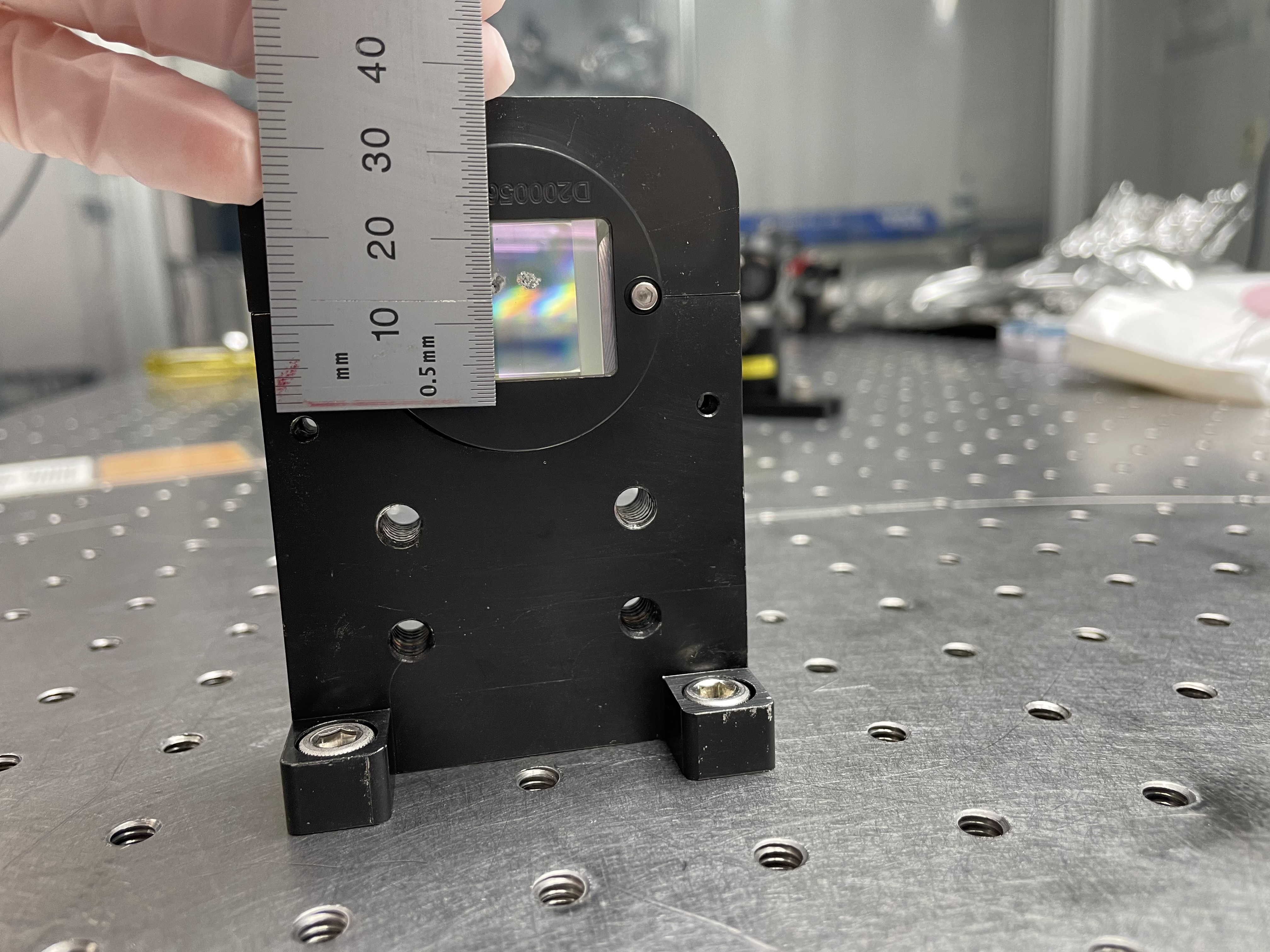
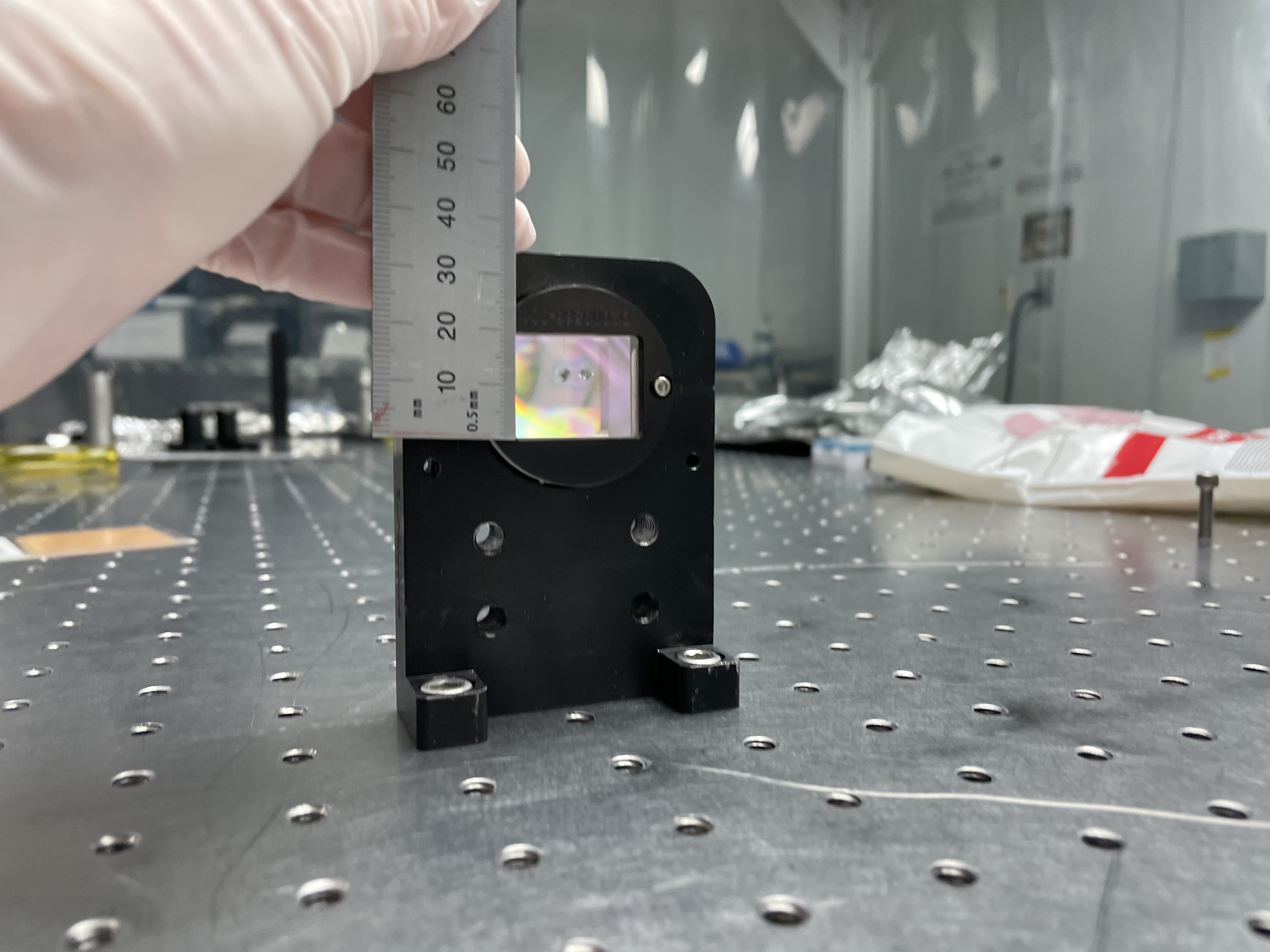
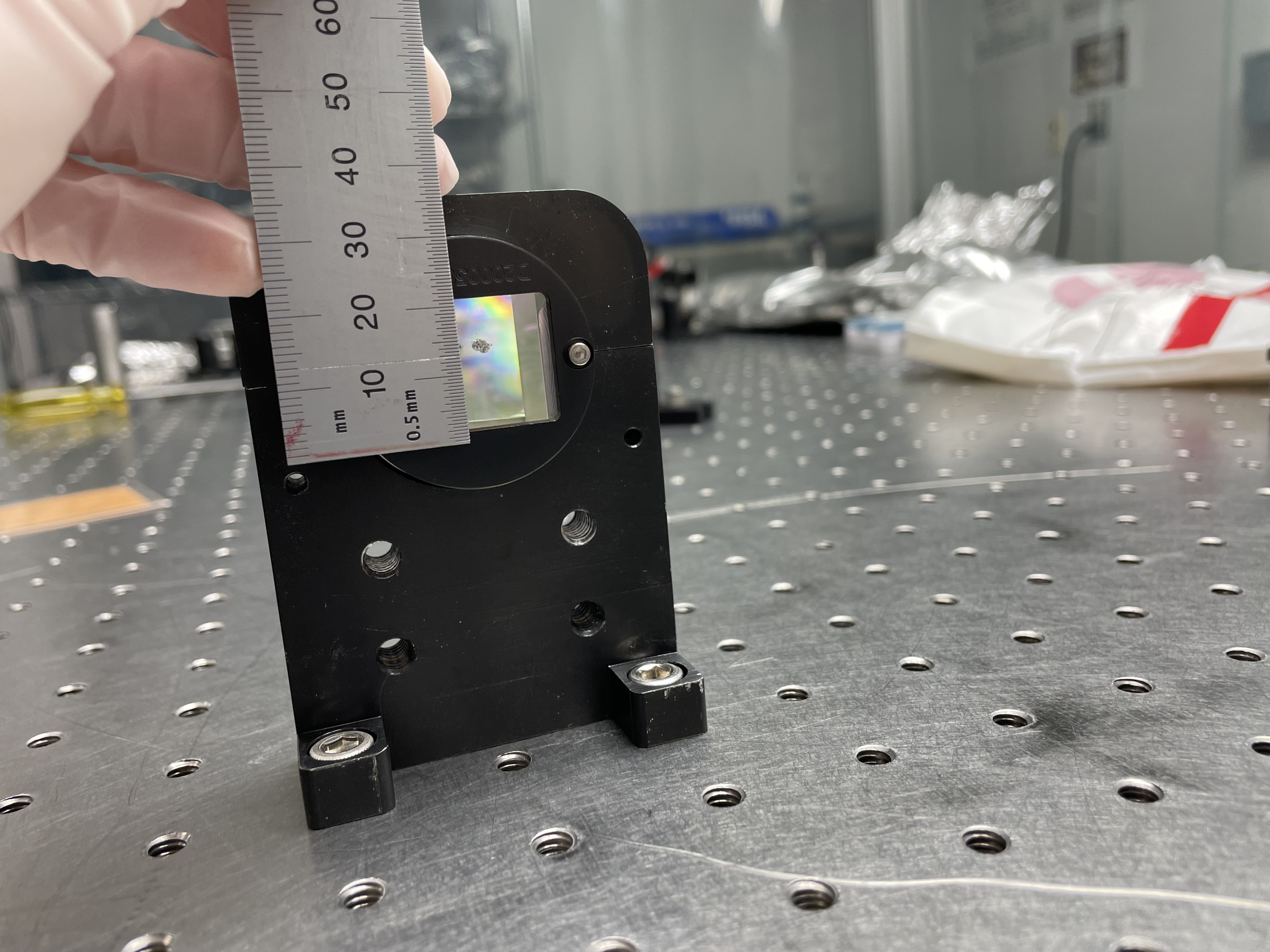
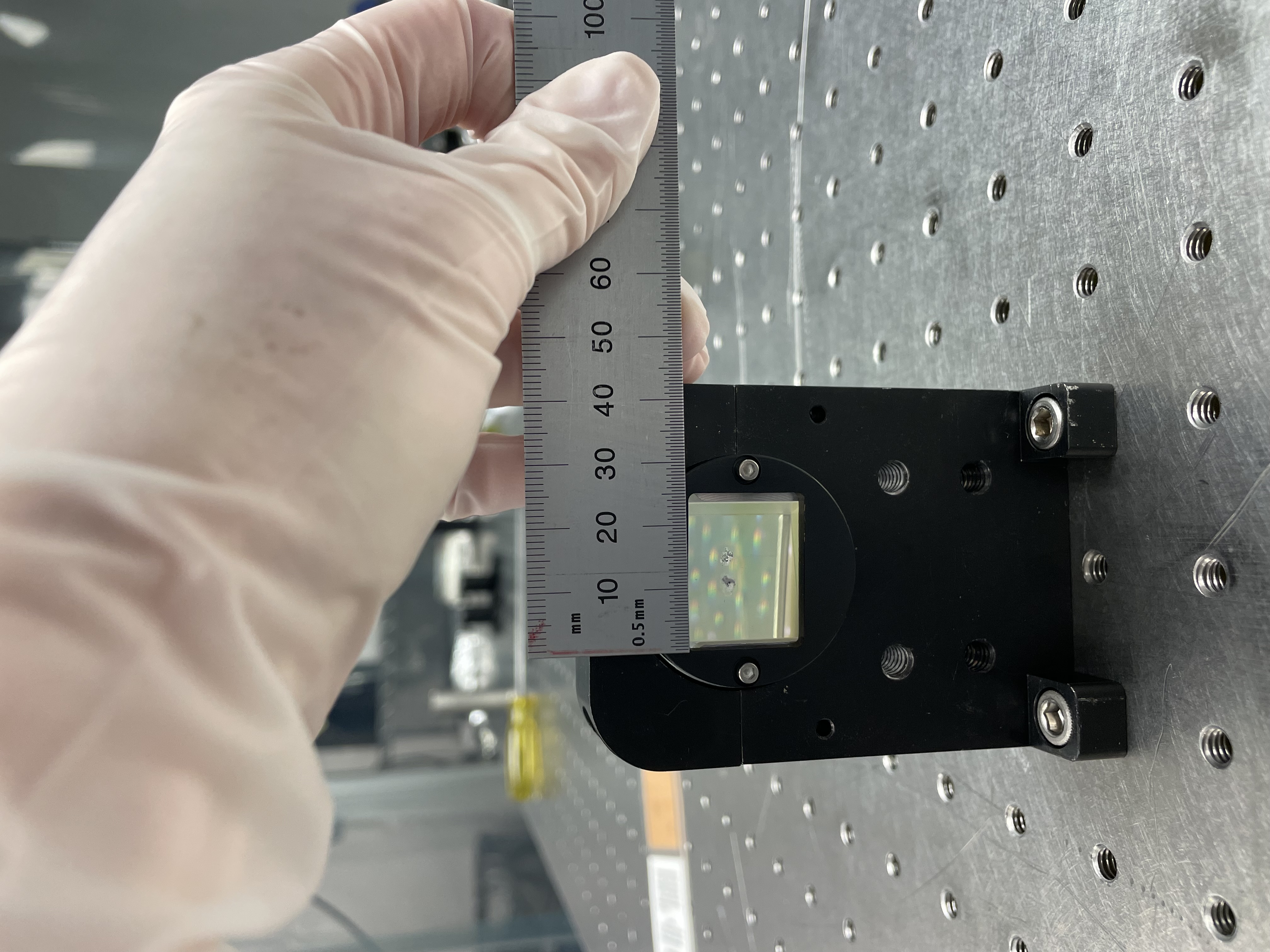
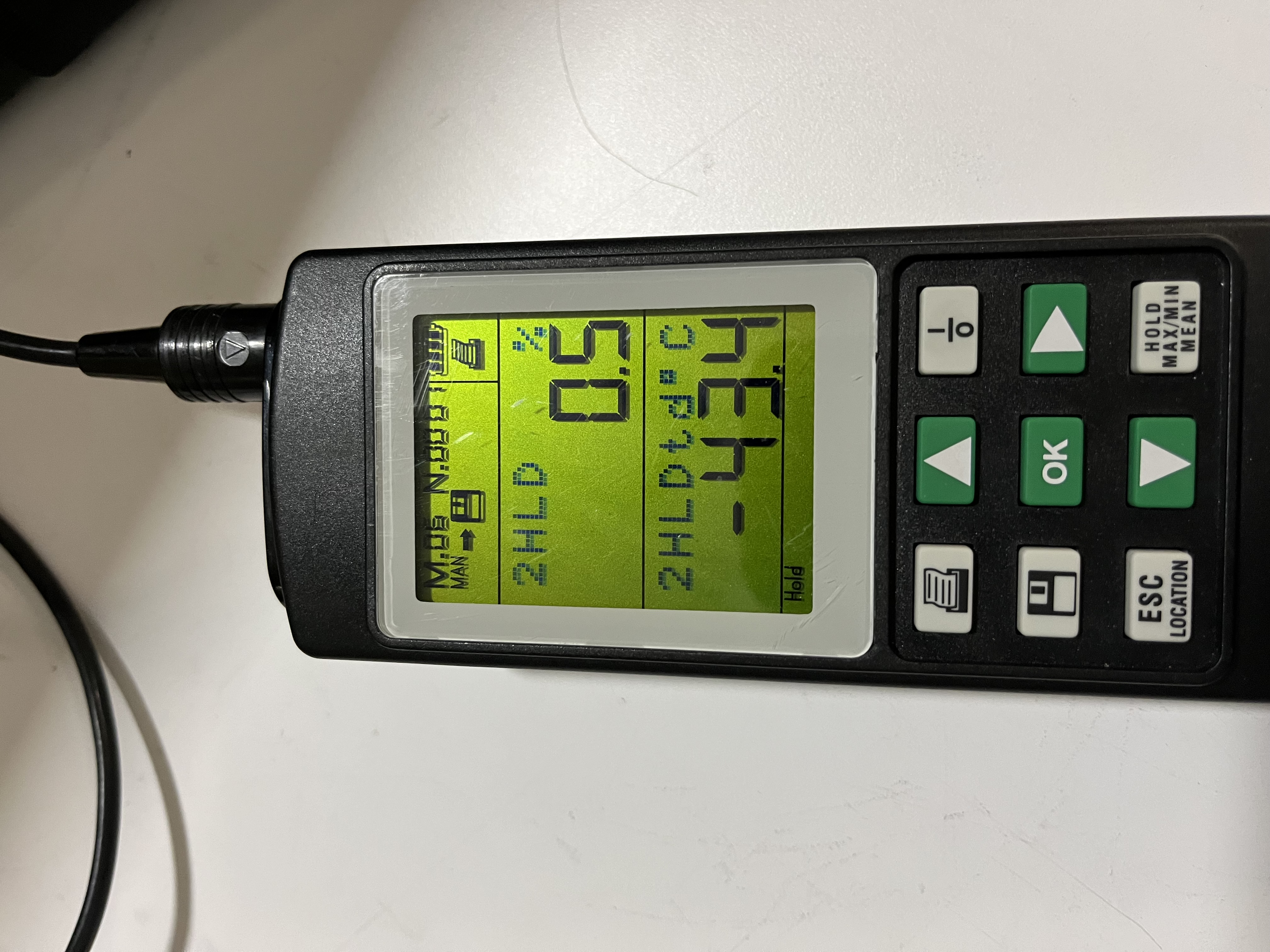
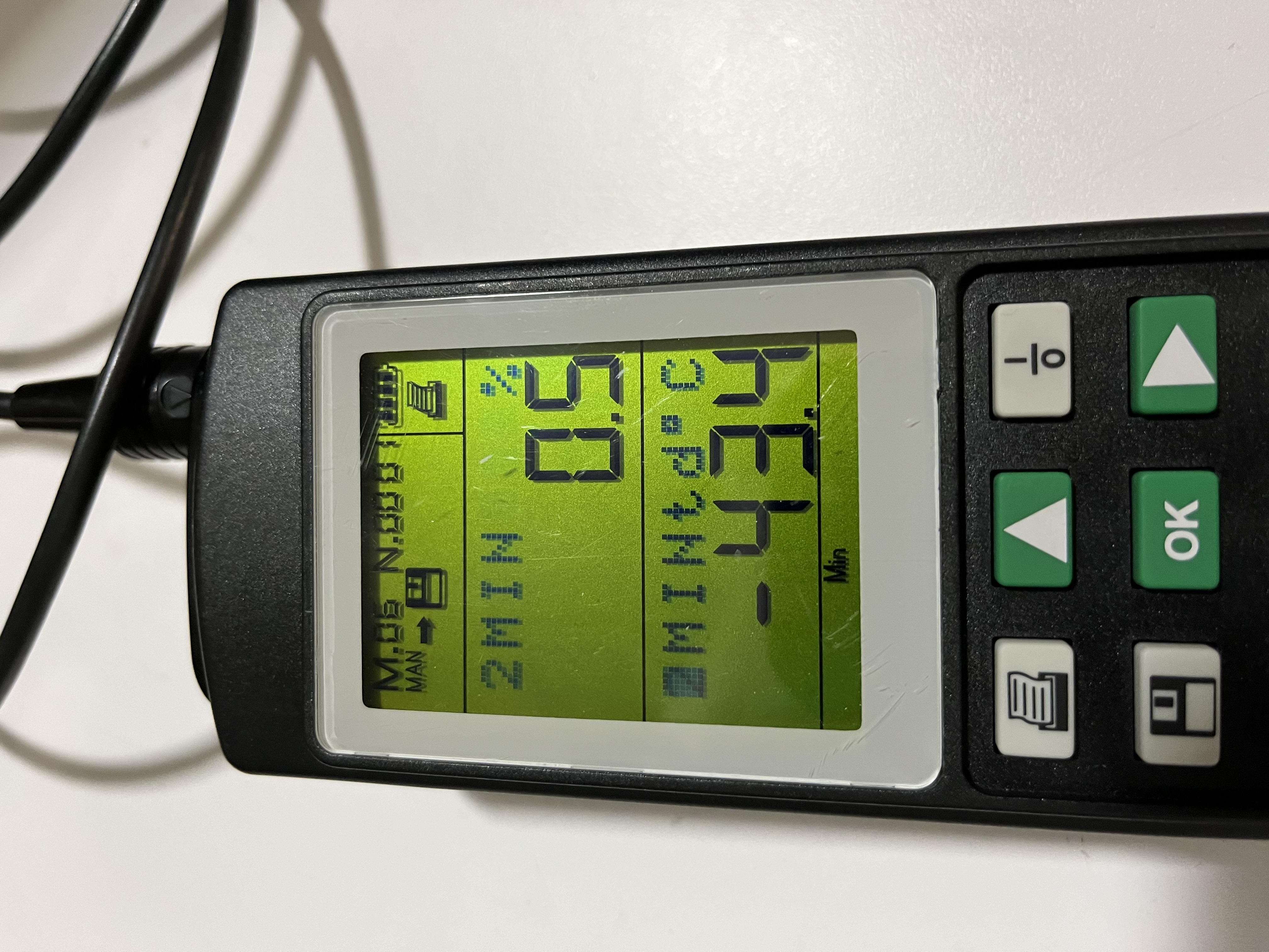
Keita made a series of measurements using calibers:
Chipped KTP: (agrees well with the drawing: E1900284)
- height on thicker side: 0.8850 inches
- heght on thinner side: 0.8845 inches
- width (center to center): 0.8870 inches
- width from one corner to the other (longest width): 0.9360 inches
- thickness: 0.5055 for thicker side
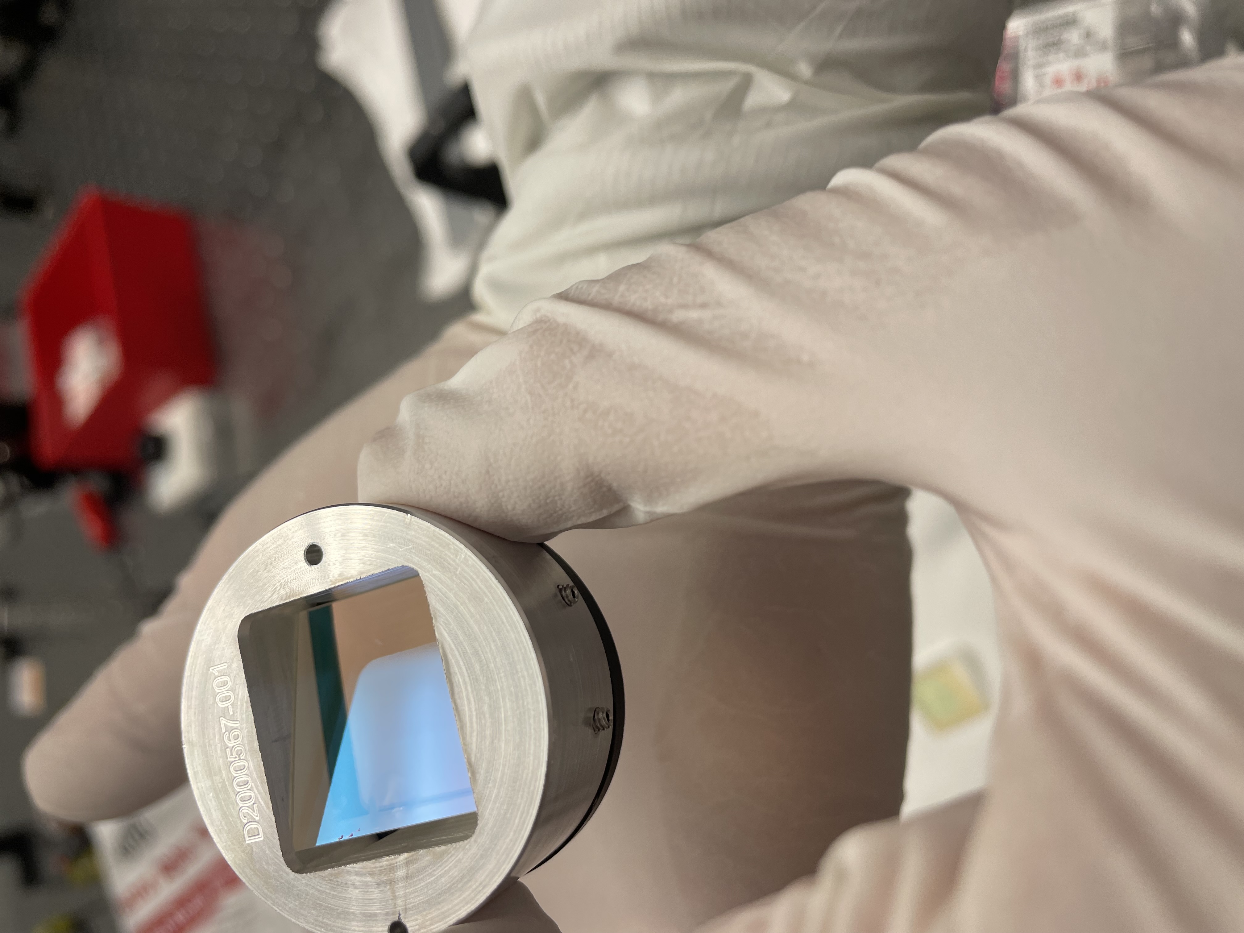
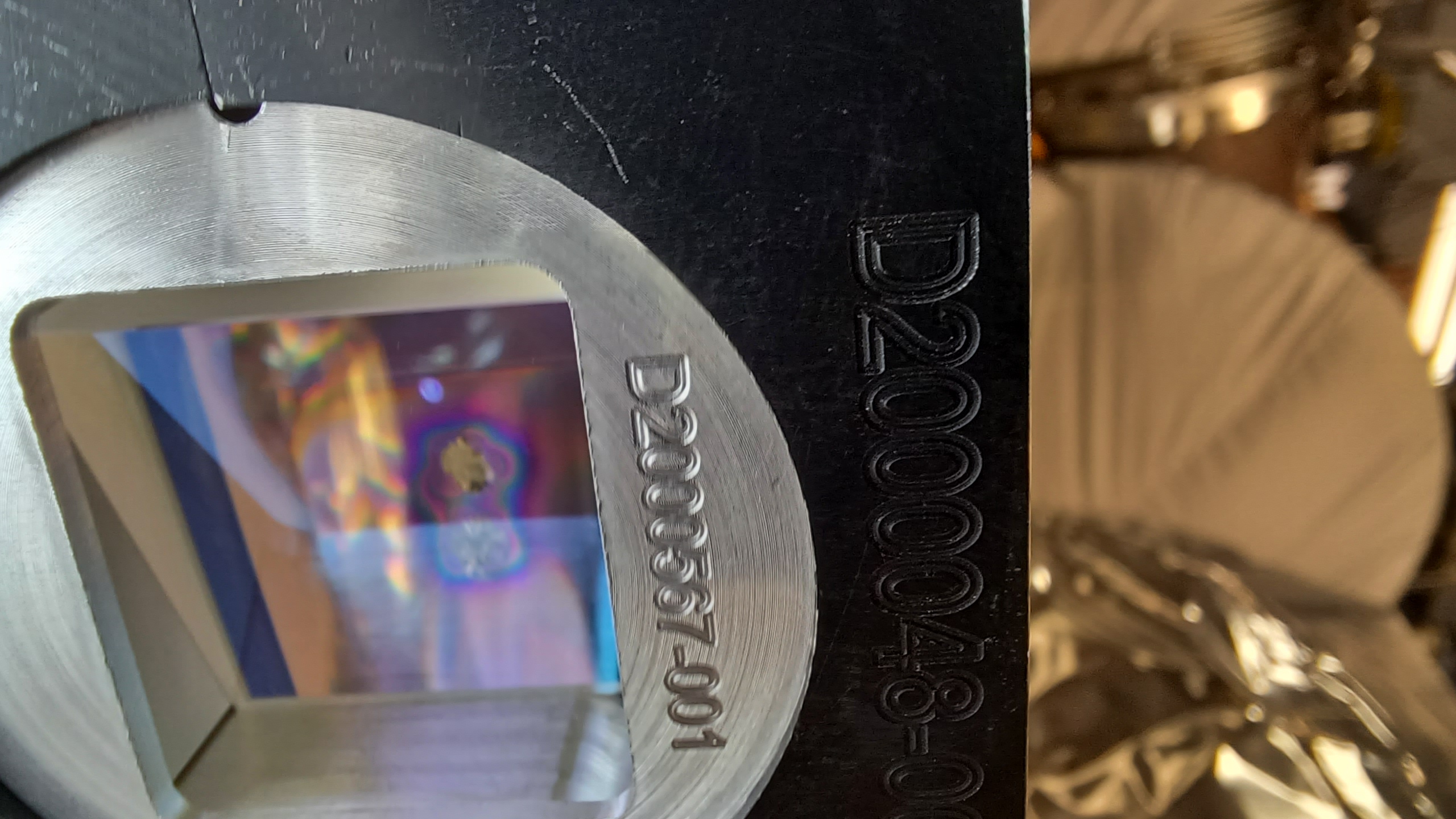
part 5: https://dcc.ligo.org/DocDB/0171/D2000567/001/D2000567_A%2B_OFI_KTP_Wedge_Holder.pdf
- side to side width of the opening for the crystal (measured on the side where the black part attaches) 0.9225 inches
- depth of the slot 0.515 inches on the deeper side.
- depth of the slot 0.458 on the thinner side
- height of the slot, including space for peek, 1.003 inches
peek:
- thickest part 0.1105 inches
- thinnest part: 0.1095 inches
total height (max): crystal + peek = 0.885+0.1105 = 0.9955 inches, smaller than 0.2mm than the height of the slot.
cratered KTP:
- height of crystal at thick side 0.8855 inches
- height of crystal at thinner side: 0.8835 inches
- width (center to center): 0.887 inches
- width diagonal: 0.9345 inches
- thickness of thicker side: 0.5095 inches
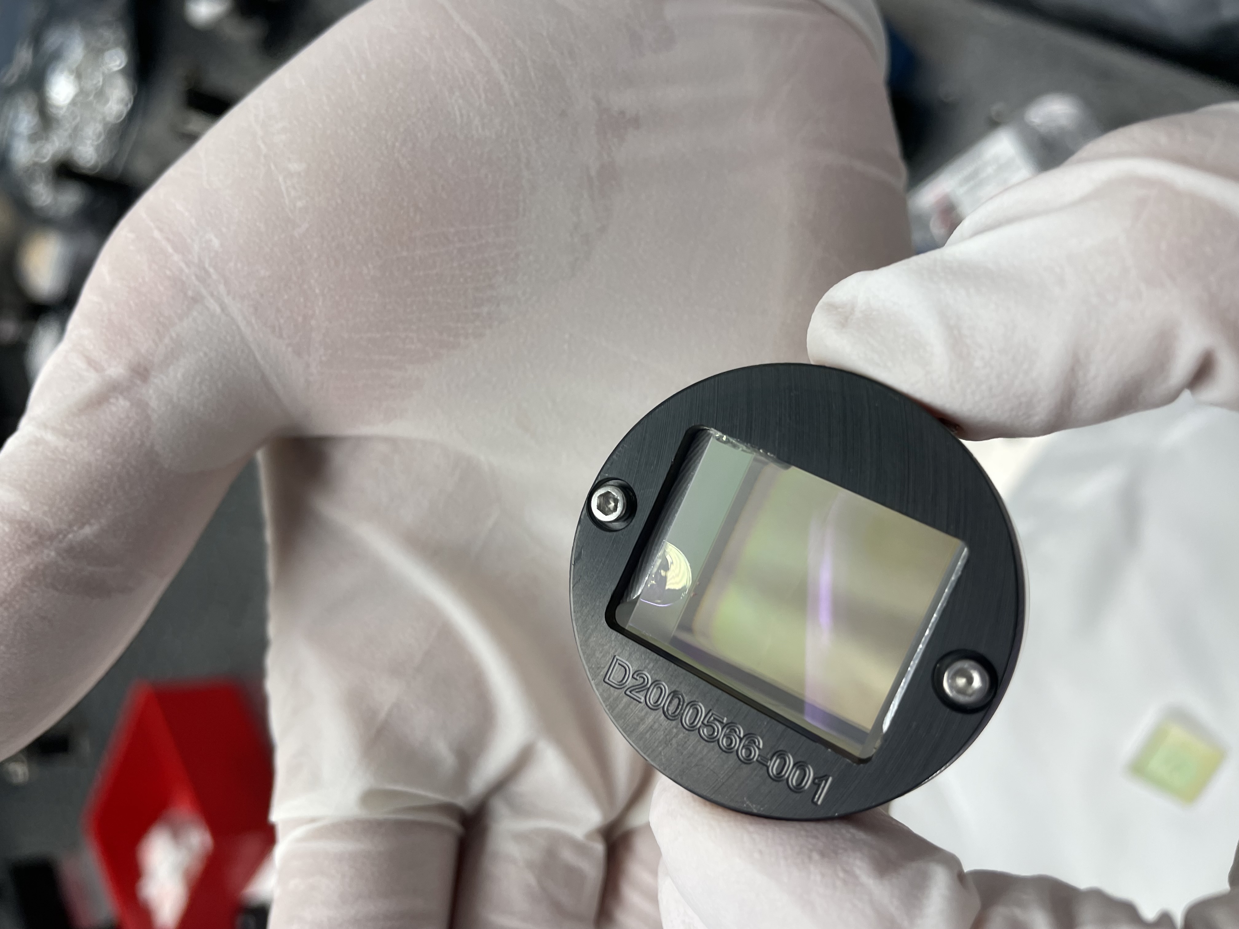
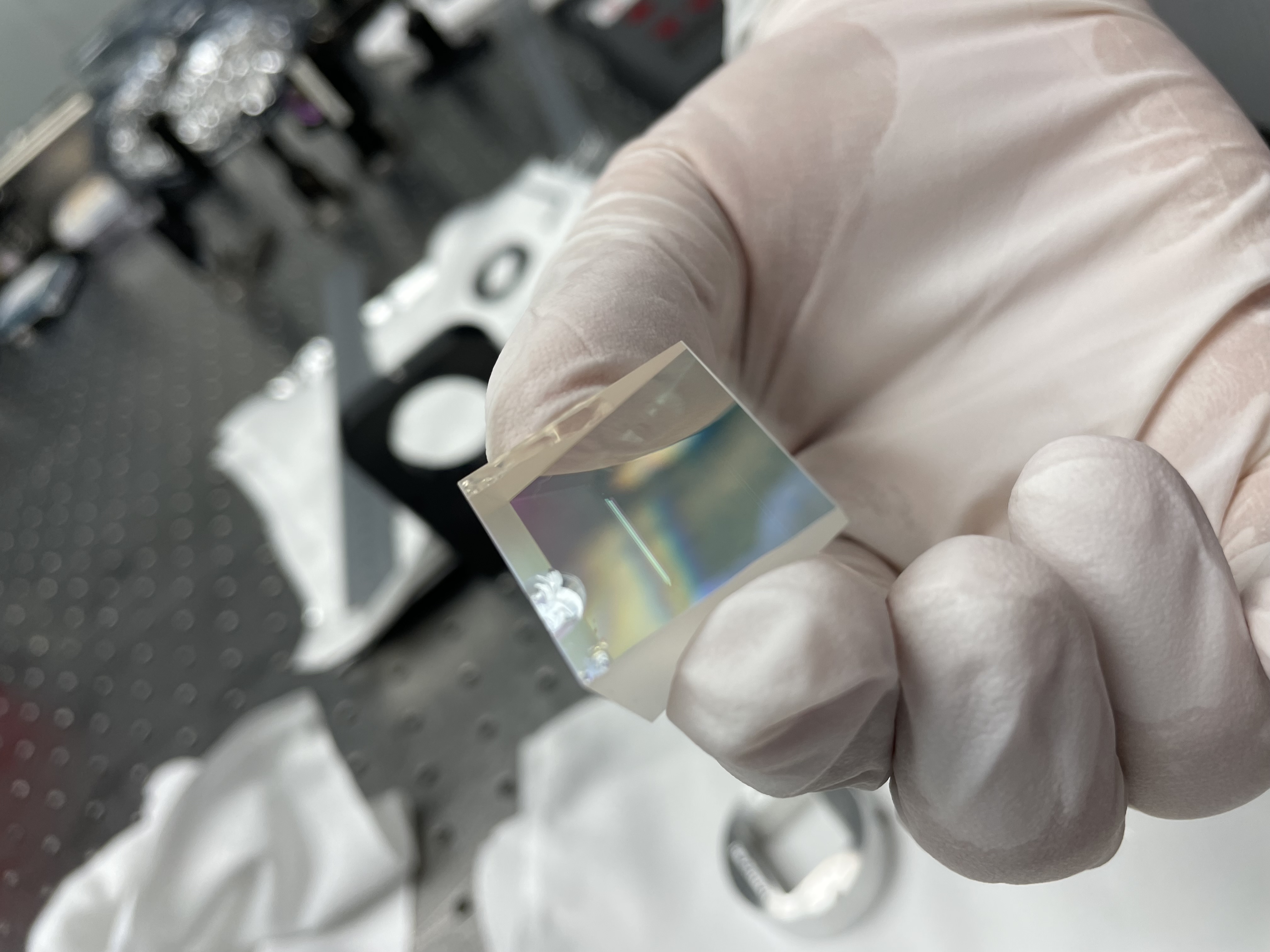
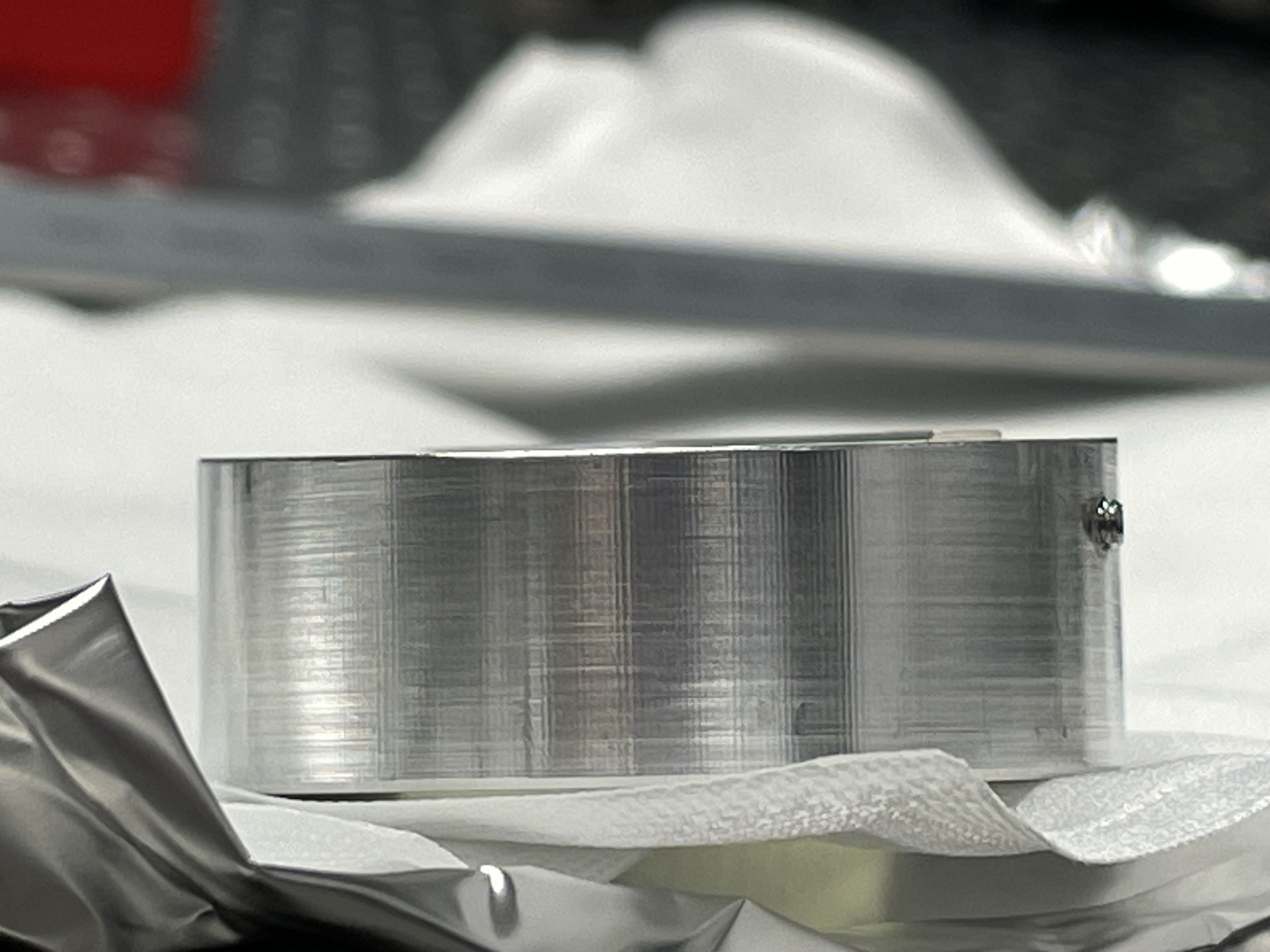
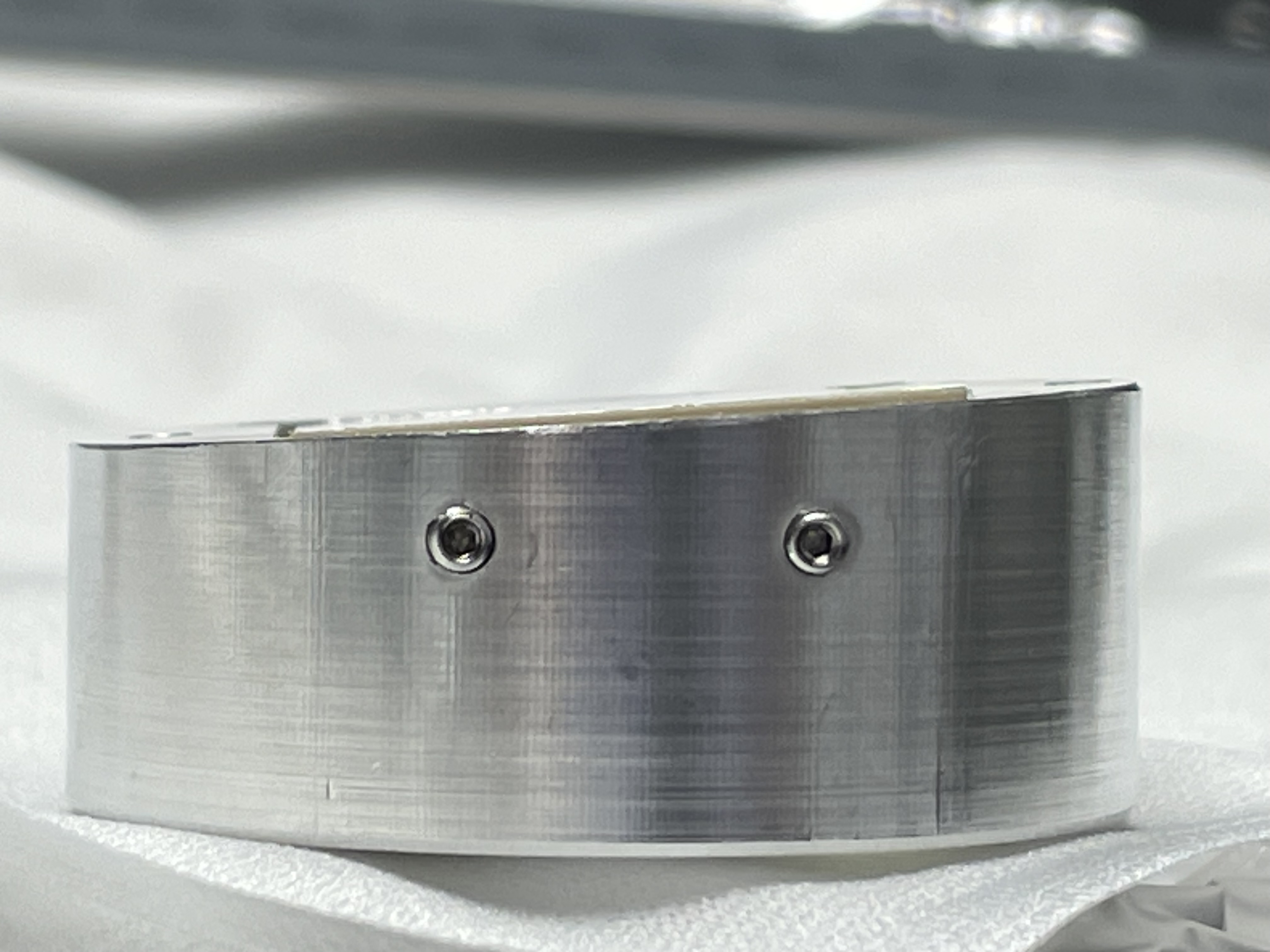
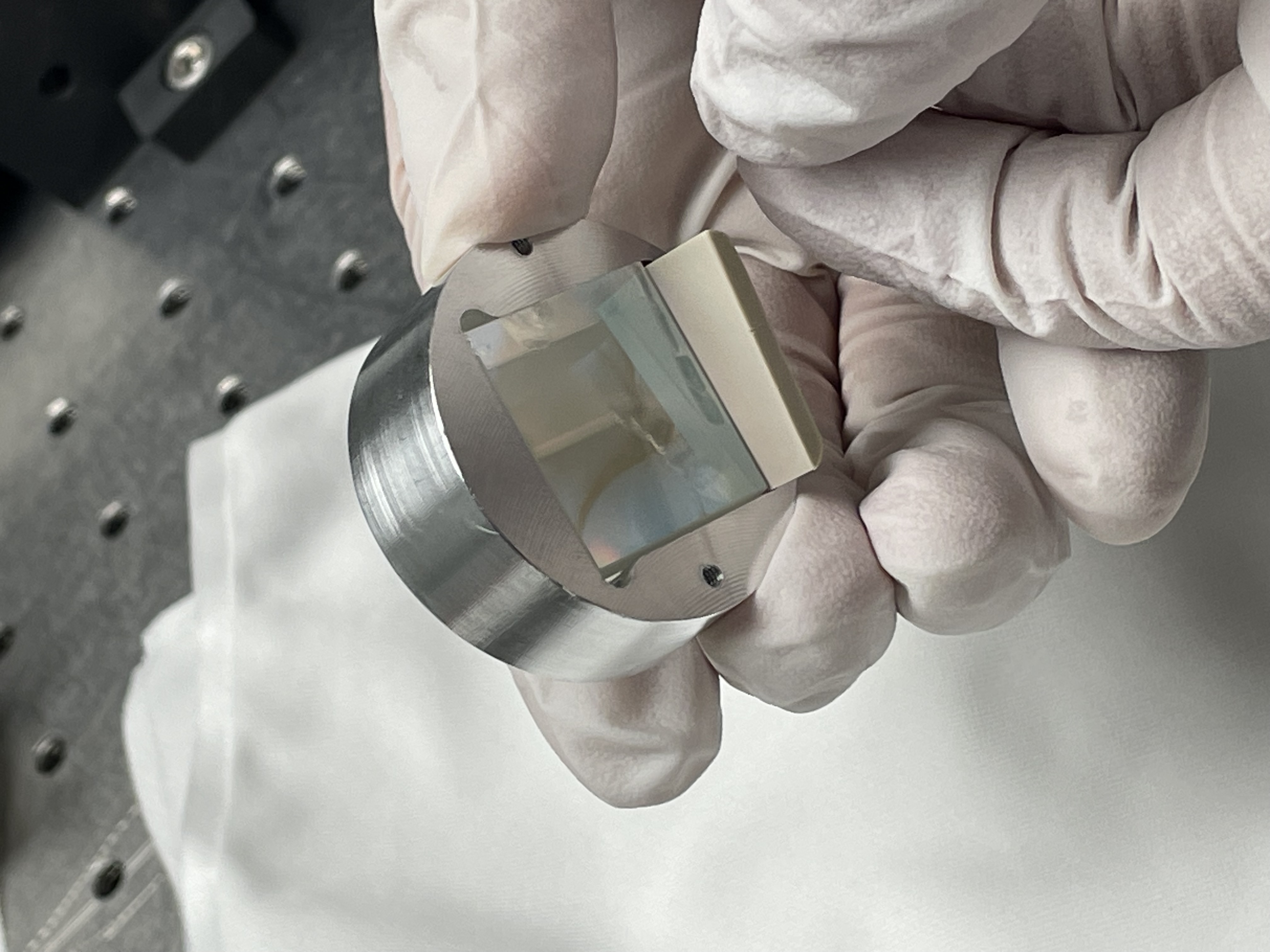
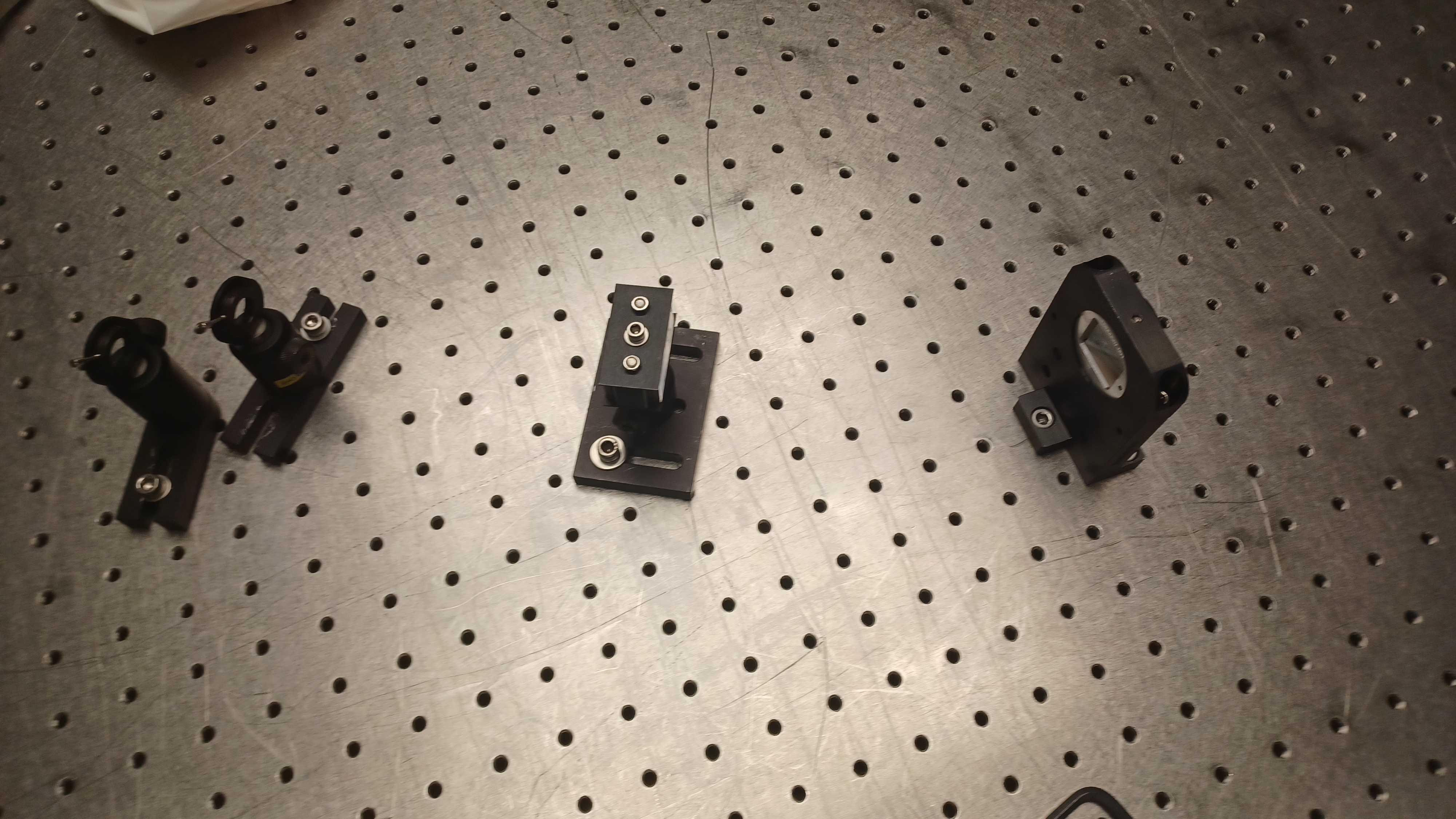
We then did a trial run (using the chipped KTP) of an approach that we think avoids the problem of letting the KTP get wedged in the holder. We set the KTP on several wipes on the bench, and set the peek underneath it. We then slid the holder (part #5) over this whole thing, which went smoothly, and tightened the set screws. After flipping it over, we can see that the KTP is not proud of part #5, and it sits nearly flush to the front of the holder. We could then easily attach the black front plate. We decided to do this with the final spare, which had 2 small chips on the edge.
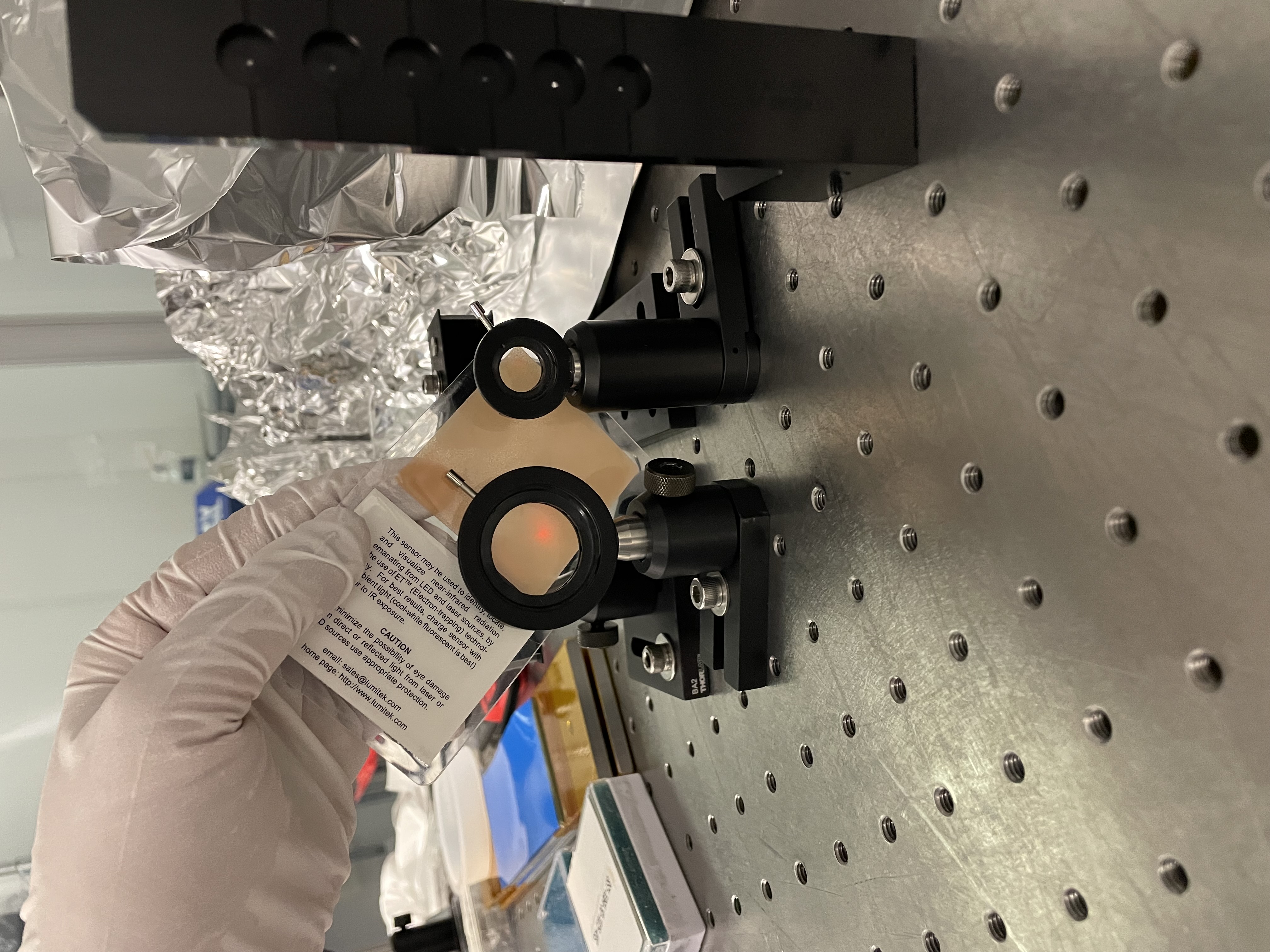
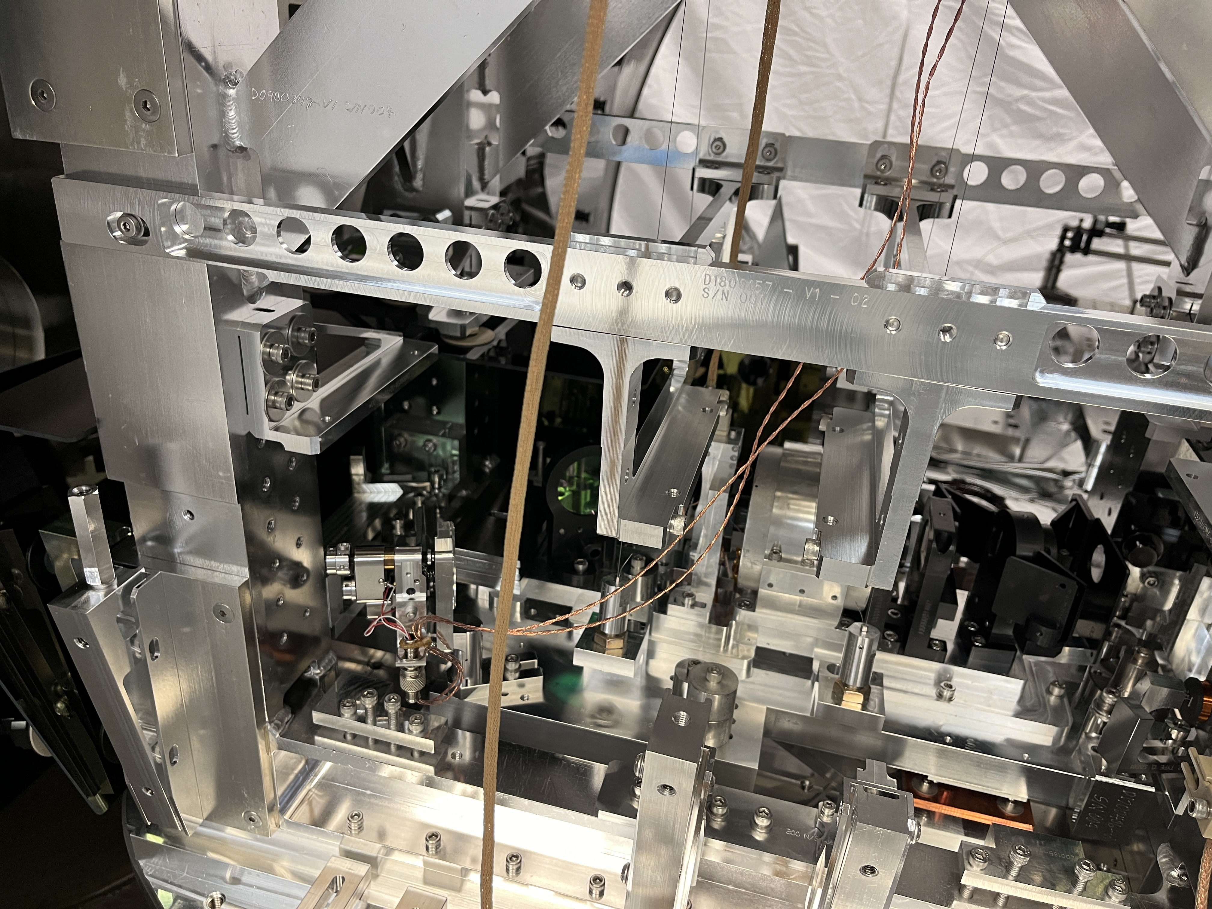
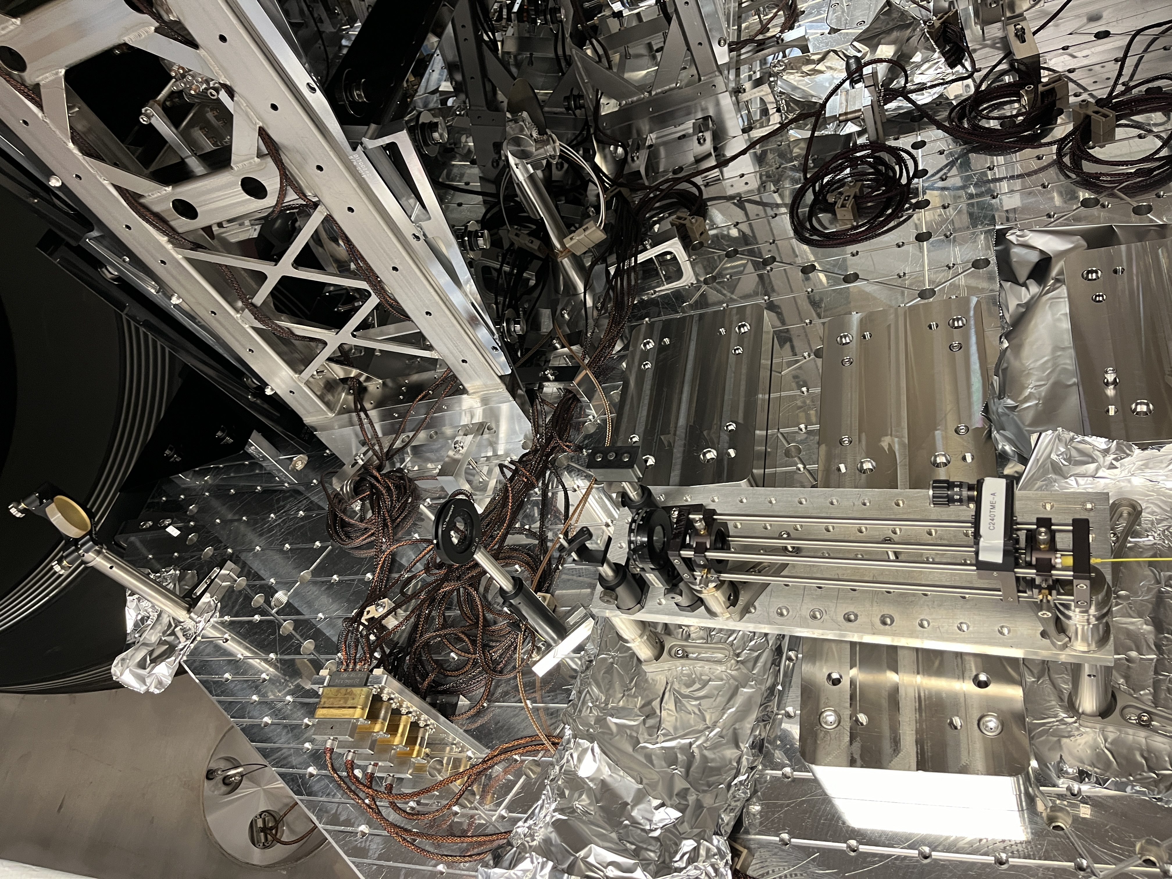
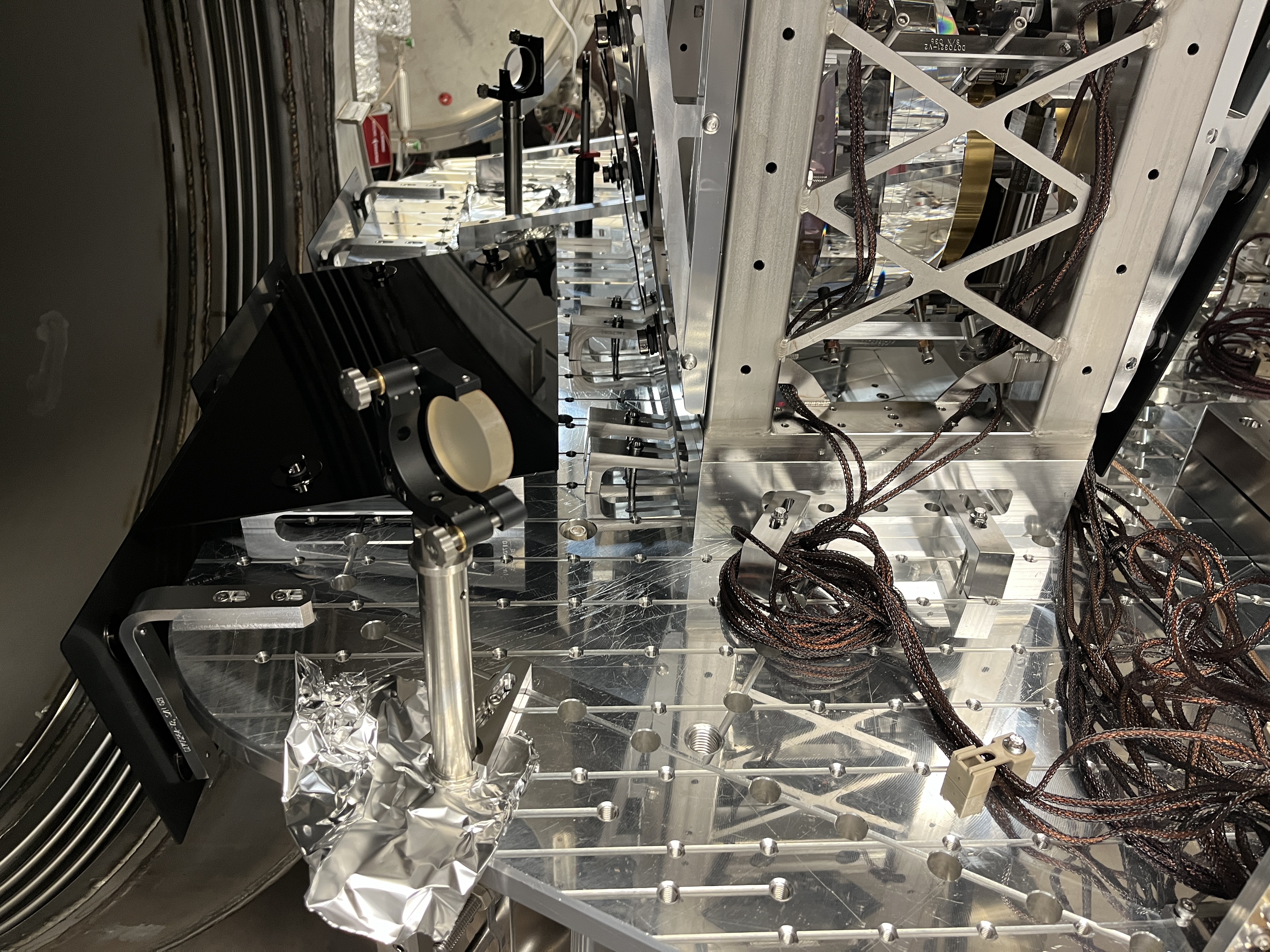
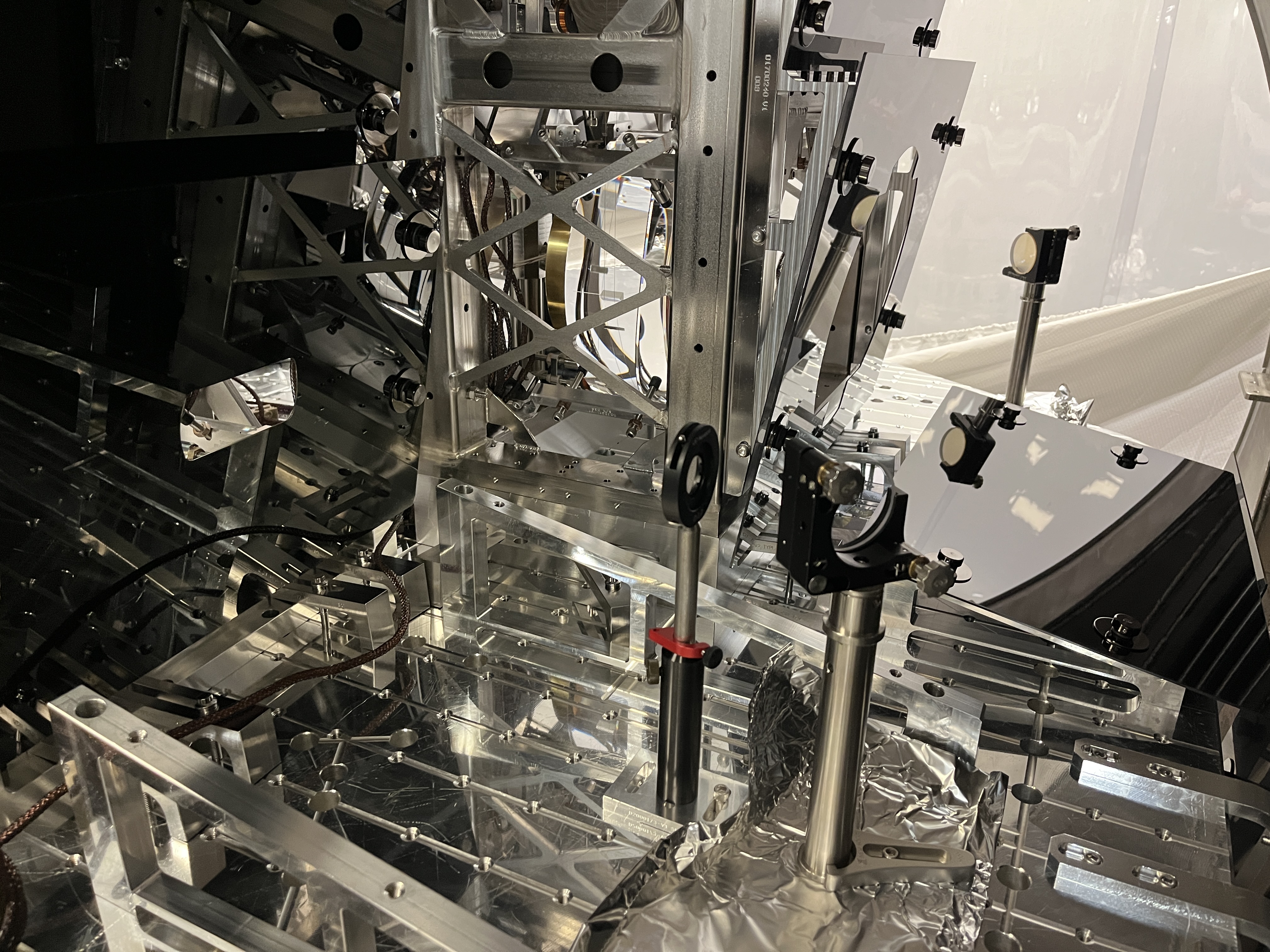
With that spare installed in the assembly, we adjusted roll using the alignment laser that Camilla and Jason set up. We wanted to adjust roll so that the transmitted beams were level to the table, since we know that the laser bea we started with were parallel to the table. The roll adjustment was sticky, and tightneing the set screw tended to lower the transmitted beams. The beams transmitted are off in yaw compared to the ones from the cratered KTP, by about 7mm/870mm + about 8 mrad. We had difficulty seeing the AR reflected beam, but we can see a tiny beam with all the lights off (this suggest that the reason the beam was so bright before was the coating damage, not the AOI of the crystal in our set up.). At 820 mm from the KTP, the AR beam was about 1 mm too low, so it's pitched down by 1mrad.
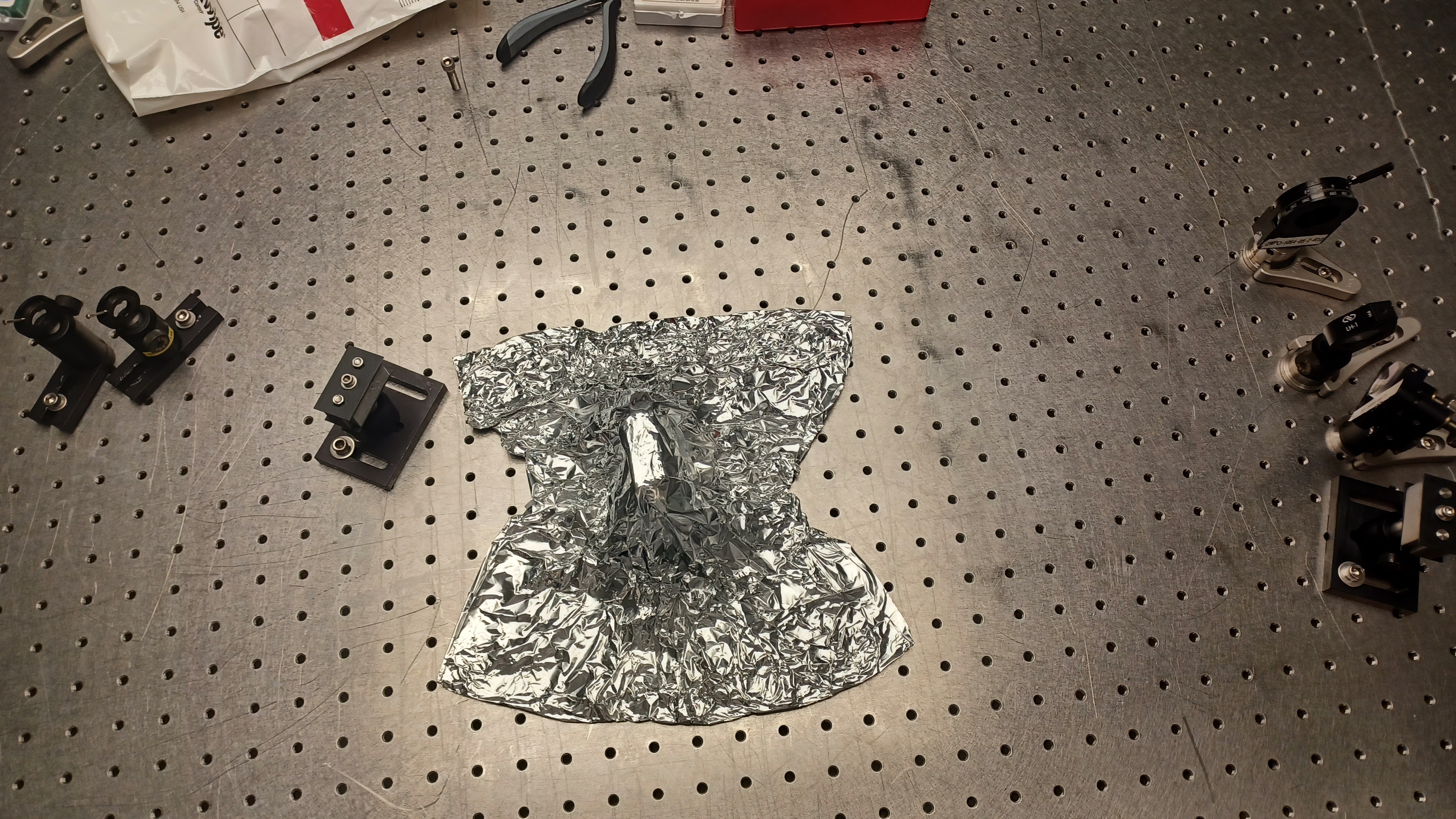
We think this is about as good as we can do by adjusting with this mount, so we are satisfied and will leave the KTP assembly under wipes and foil to be reinstalled on Monday.