Camilla, Jason, Jenne, Keita, Sheila, Francisco, Naoki
Summary: We are done for AUX laser alignment and power measurement of AUX laser. SQZ beam got to OM1, but we did not do power measurement due to noisy seed dither lock. The following are a mixture of notes between Camilla, Francisco, and Naoki regarding the changes done today:
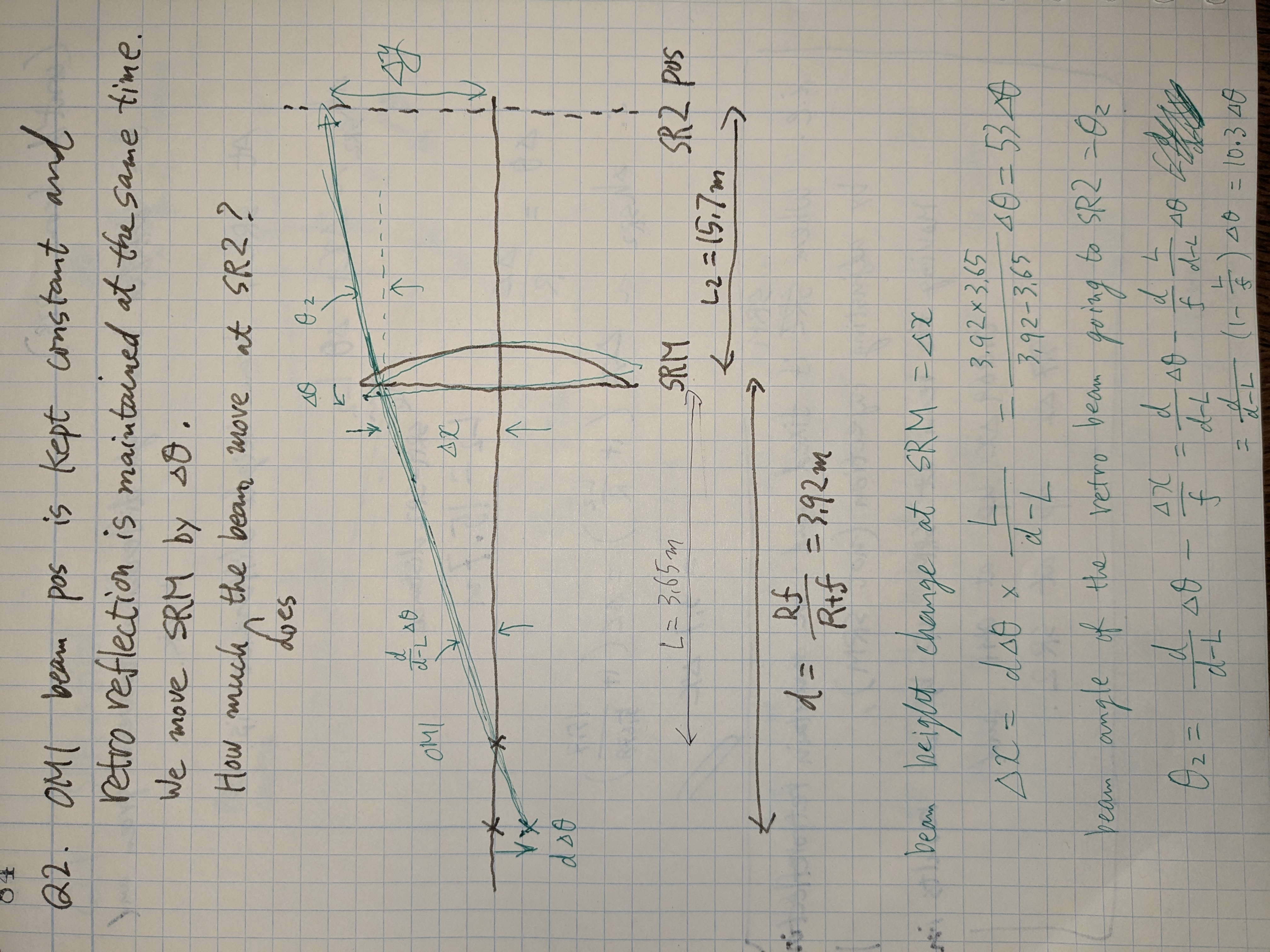
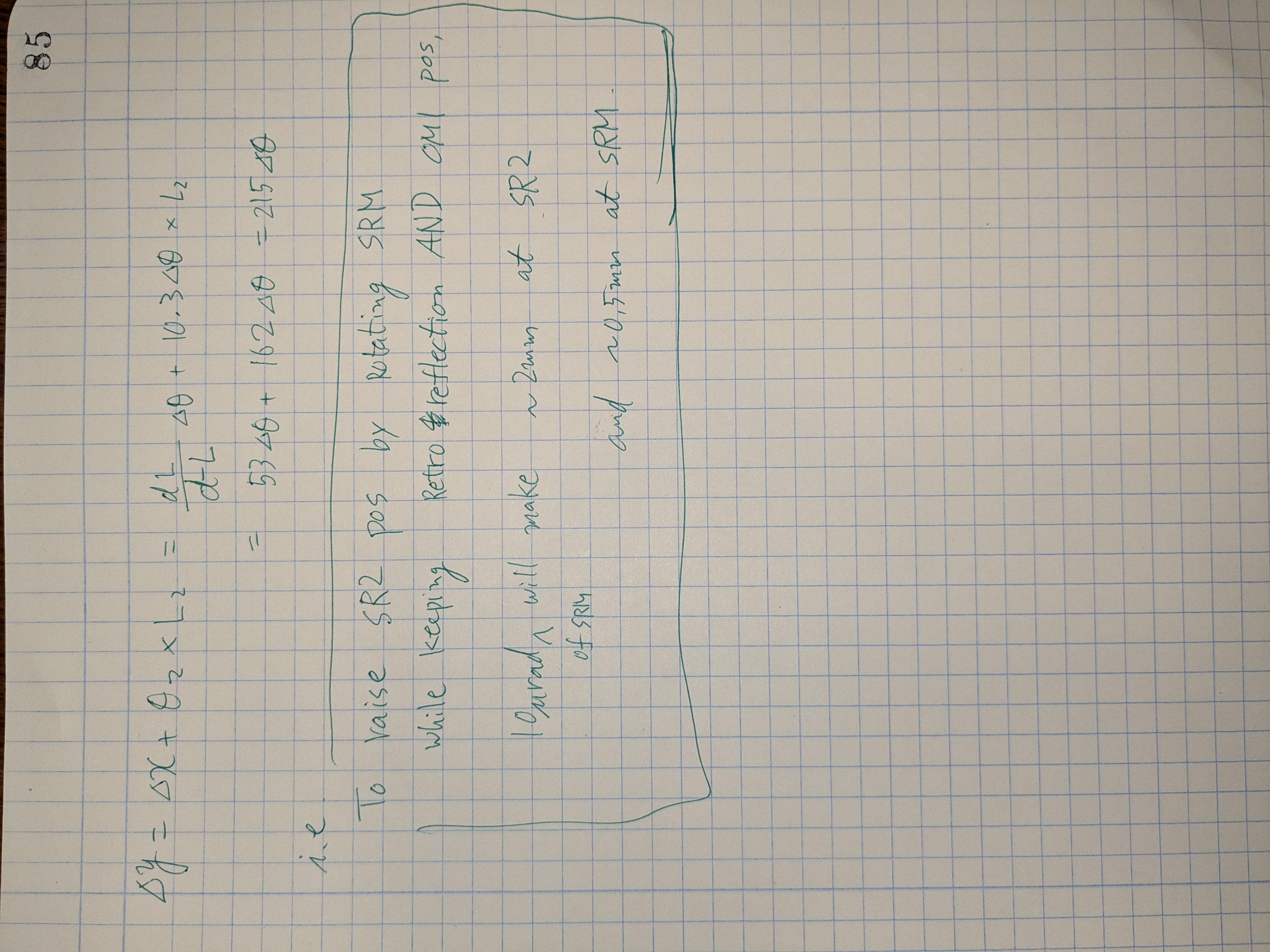
Aiming for 2 1/4" above EQ stop as 4" between vertical stops and the center of SR2 optic is 5.5mm above center line of EQ stops.
At start of the day, someting had drifted (mainly pitch), re-centered AUX laser on irises.
*Iterating moving auxiliary laser mirror and beamspiltter to center in om1 and retroreflection irises.*
Checking position at SR2:
- 1 1/4 in above EQ stop
- 1cm in +x from the center
Swapped the AUX laser steeing mirror to a better optic mount and not woberly perdistal, we are blaming this for our drift.
Jenne also adjusted SRM sliders to yesterdays values.
*Iterating moving auxiliary laser mirror and beamspiltter to center in om1 and retroreflection irises.*
Checking position at SR2:
- 1 1/2 in above EQ stop
- 1cm in +x from the center
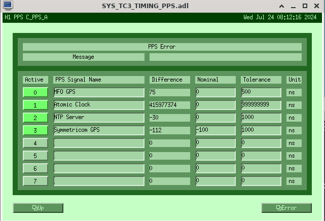
Moved SRM osems from (175, 140) to (50,190). In pitch moved -125urad from 175 to 50 on osems. In yaw moved +50urad. this was 140 to 190 on osems
Aiming to center the beam on SR2
*Iterating moving auxiliary moving mirror to center in om1 and retroreflection irises.*
Checking position at SR2:
- 2 1/4 in above EQ stop
- 3/4 in from +x EQ stop
- yaw got "worse"
EQ stops are 2 1/2 in away from each other; center is 1 1/4 in from horizontal EQ stop
Will do 100 microrad in -YAW, then check retro in OM1. -100urad in yaw is 190 to 90 on osems
*Iterating moving auxiliary moving mirror to center in om1 and retroreflection irises.*
Checking positions at SR2:
- 1/2 in away from horizontal EQ stop
- Went wrong direction
In yaw going +300 urad. This is 90 to 390 on osems.
*Iterating moving auxiliary moving mirror to center in om1 and retroreflection irises.*
Checking positions at SR2:
- 1 1/4 in away from horizontal EQ stop (nice.)
- 2 1/2 in above bottom of EQ stop
*LUNCH BREAK*
Sheila back to SR2;
- 2 1/2 inch above bottom of EQ stop
- yaw is still good
earlier today SRM P moved from 179 to 50. 1 1/4 inch move on SR2
Moved 1/4 inch backward. moved SRM P from 50 to 76
Sheila is happy with SR2 centering.
Jason is setting iris on OM1. Beam on OM1 ugly? due to crater on OFI?
ASC_AS_C P -0.6 Y -0.6
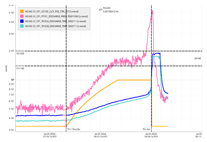
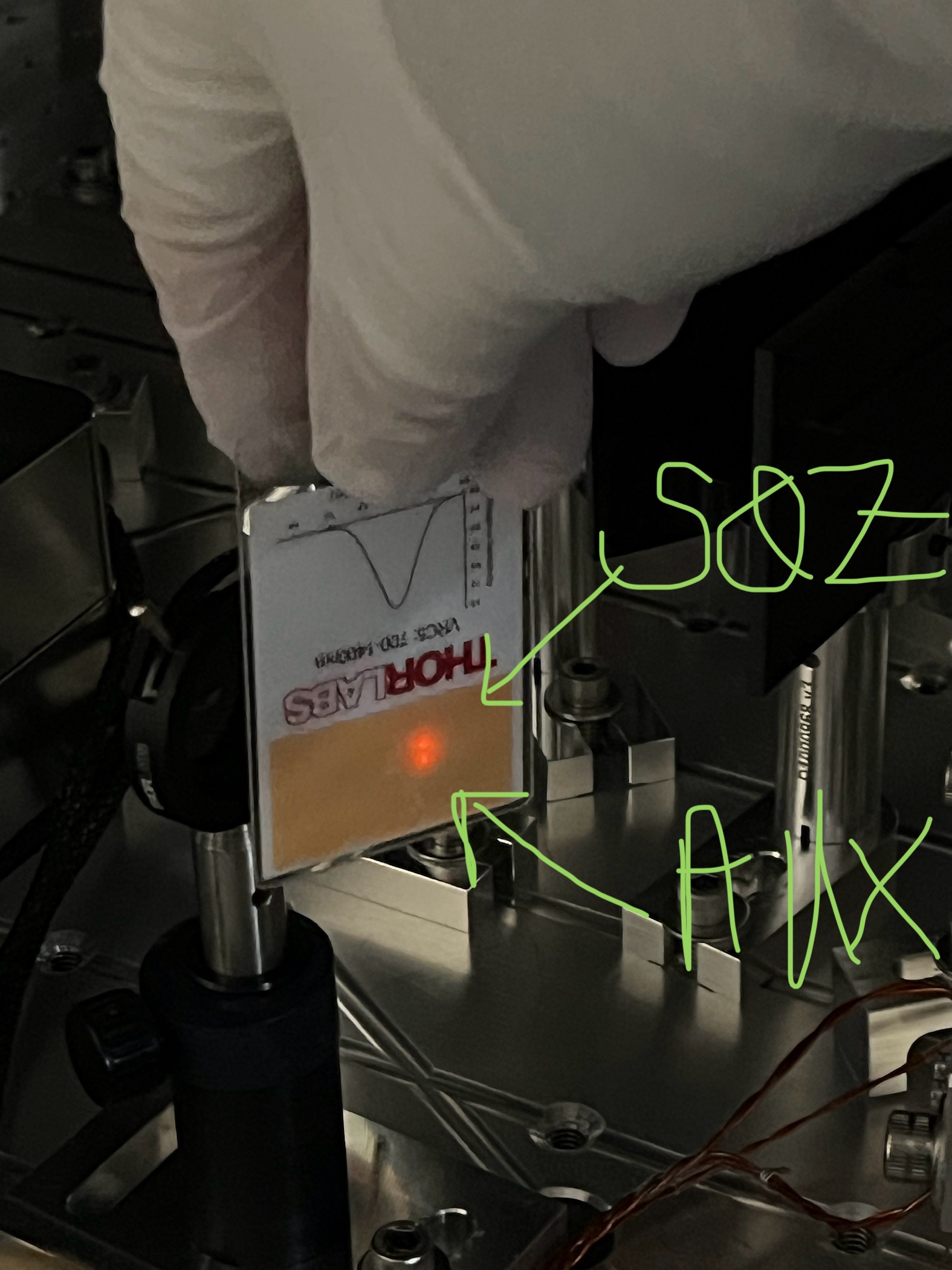
open GV for HAM7. send SQZ beam. seed dither lock is very noisy.
SQZ beam is close to AUX laser?
AUX power measurement
- 1.72mW before SRM
- just after SRM 0.605mW
- before OM1 0.380mW
- 0.45mW after TGG before TFP