camilla.compton@LIGO.ORG - posted 12:37, Thursday 20 June 2024 (78554)
aligoNB injections taken
Took Jitter, MICH, PRCL, SRCL LSC, CHARD, DHARD, CSOFT, DSOFT, MICH ASC noise budget injections. Following instructions in 74681. Last taken by Sheila May 9th.
Had some git issues (whoops, I will remember to pull first next time) but the templates are committed locally in ligo/gitcommon/NoiseBudget/aligoNB/aligoNB/H1/couplings and I will work on pushing to the aligoNB git.
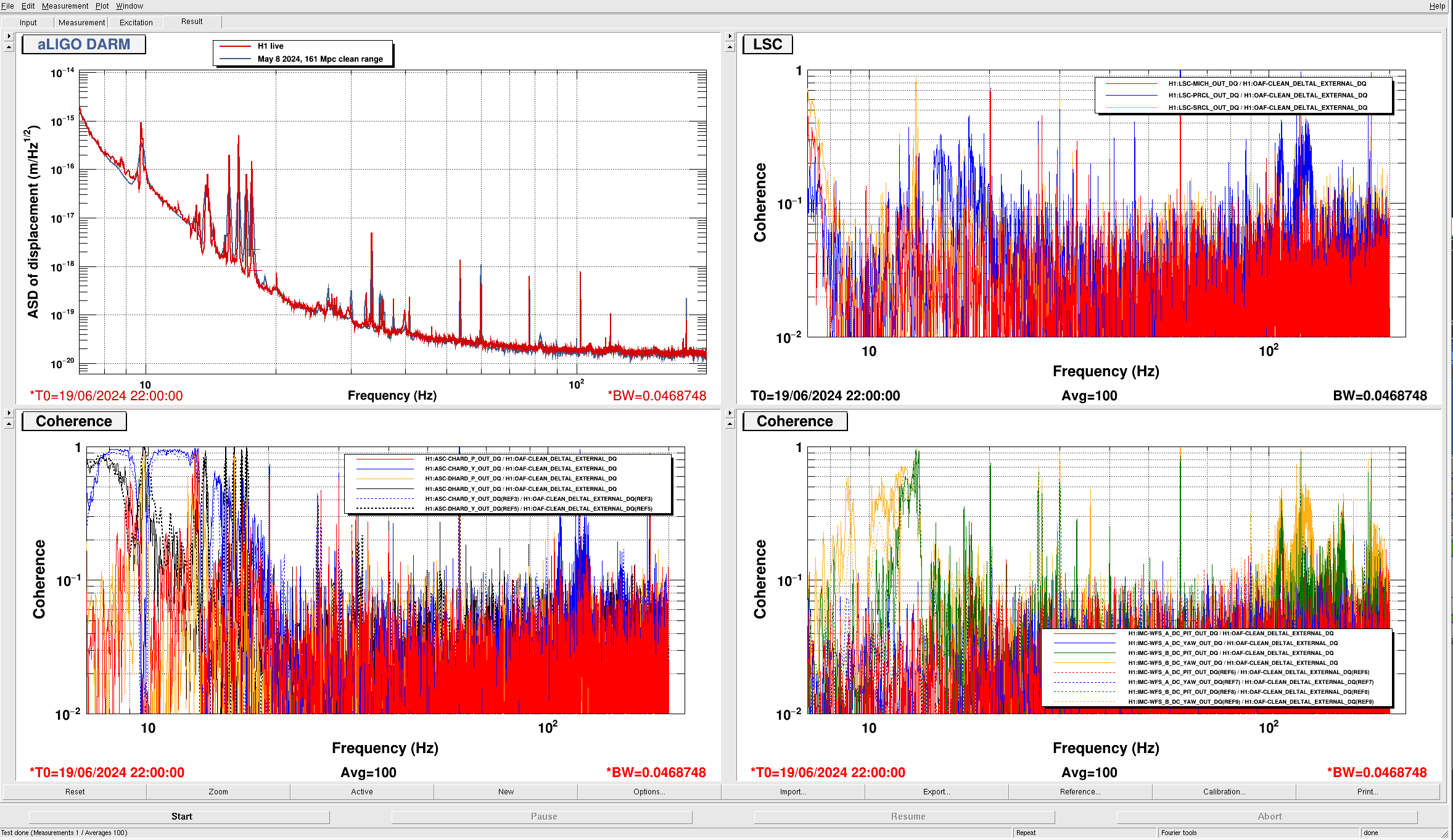
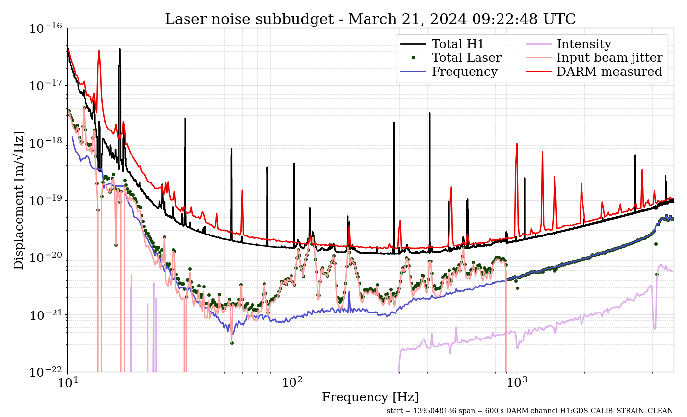
Analysis instructions in 74788. Used DARM time gpstime: 1402575668 # June 16, 2024, 12:20 UTC, Observing Time, O4b, IFO locked 10 hour, 160MPc range. Attached Jitter, Laser noise, ASC and LSC plots.
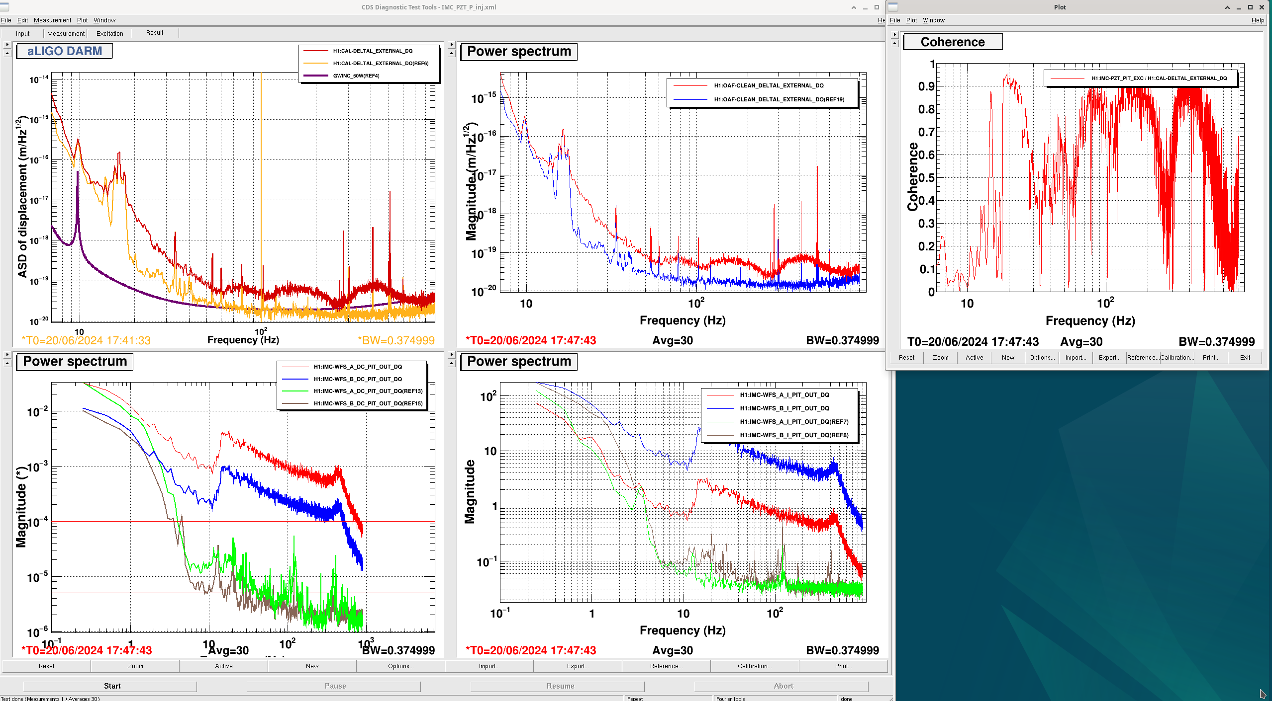
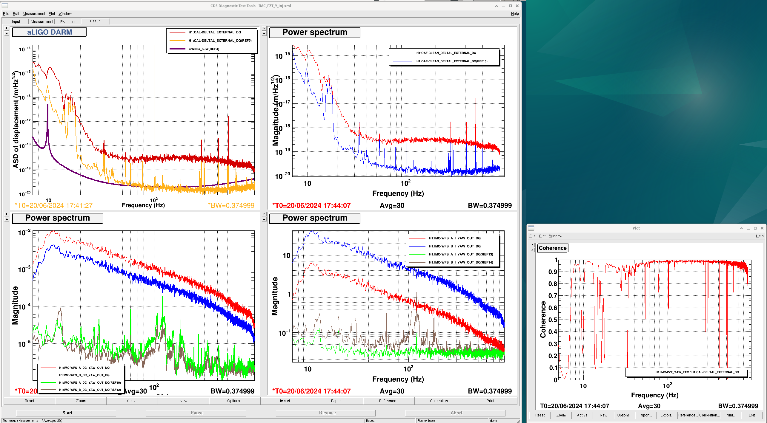
- Jitter is similar to March alog 76623: worse at 100Hz, better over 150Hz. Overall worse than December 74788
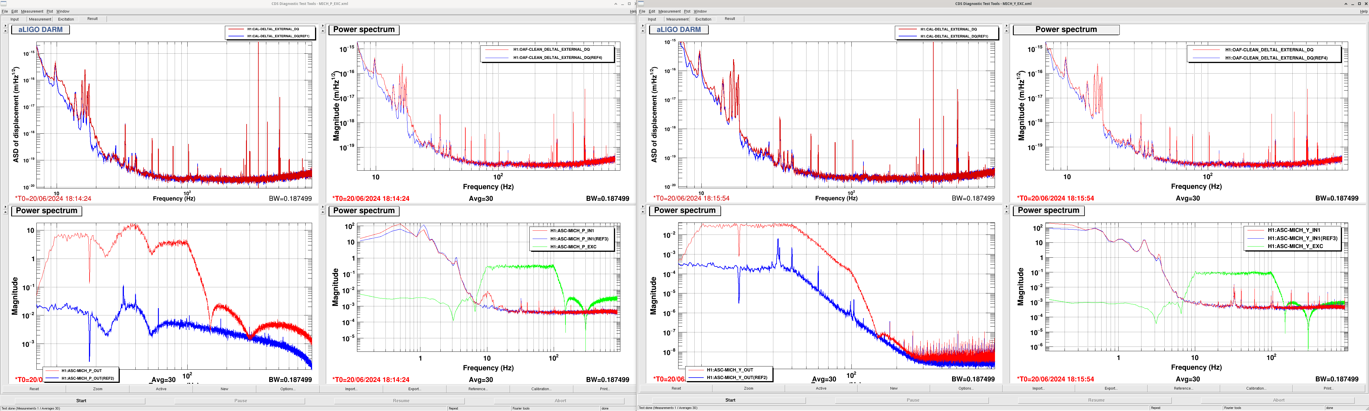
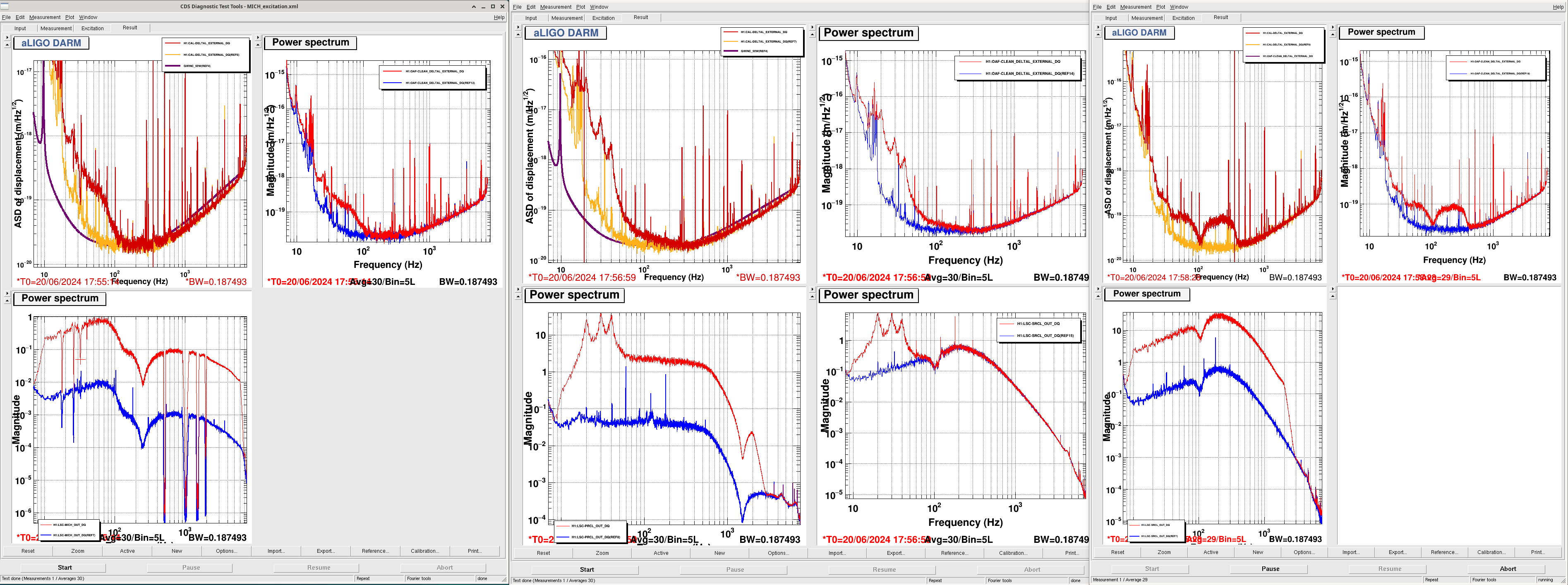
- LSC is a little worse below 20Hz, similar/better everywhere else. More SRCL at 60-100Hz than plot in December 74788
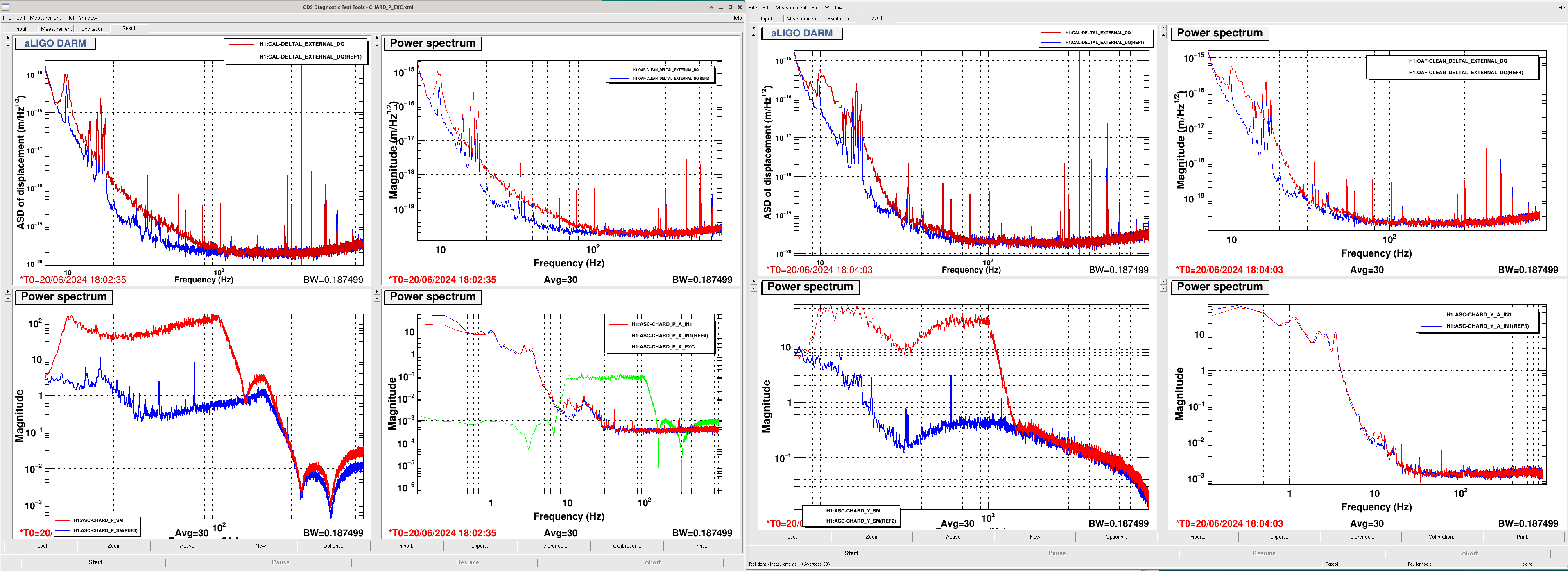
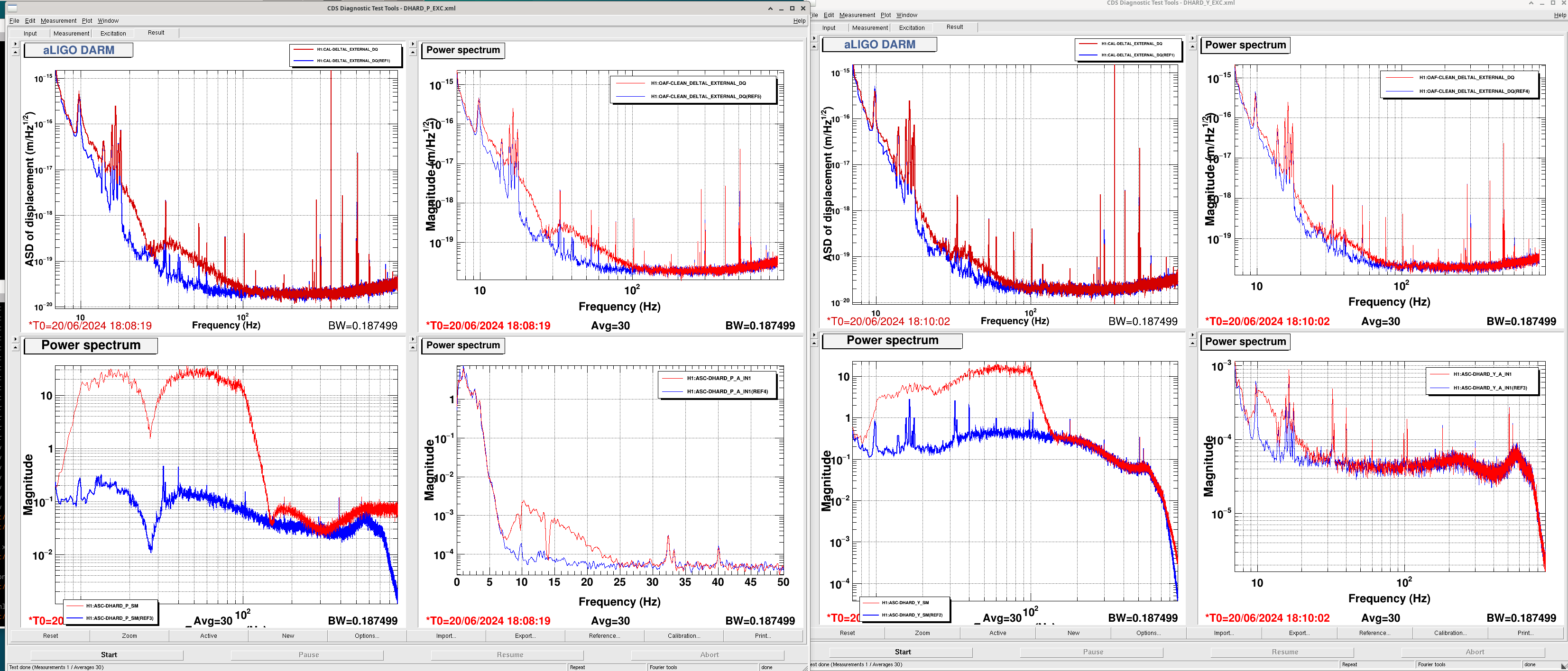
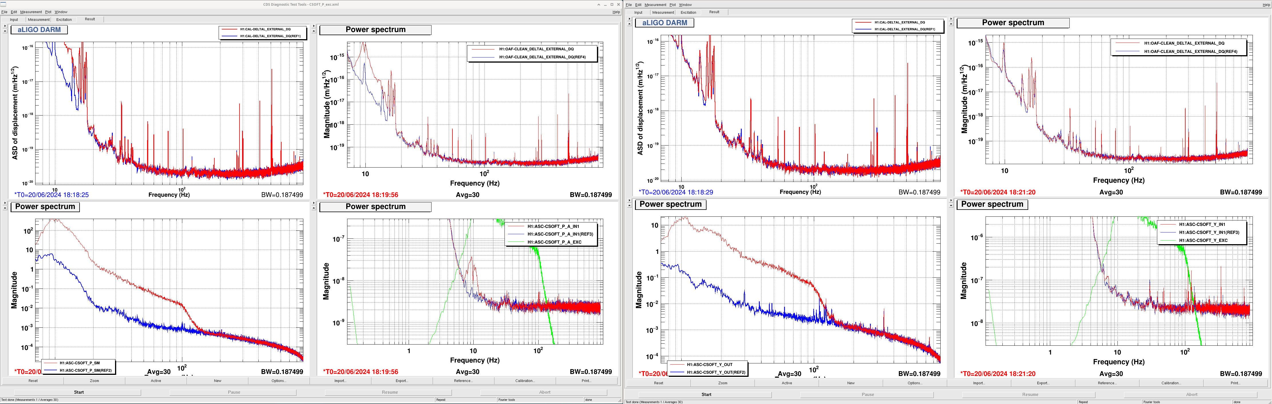
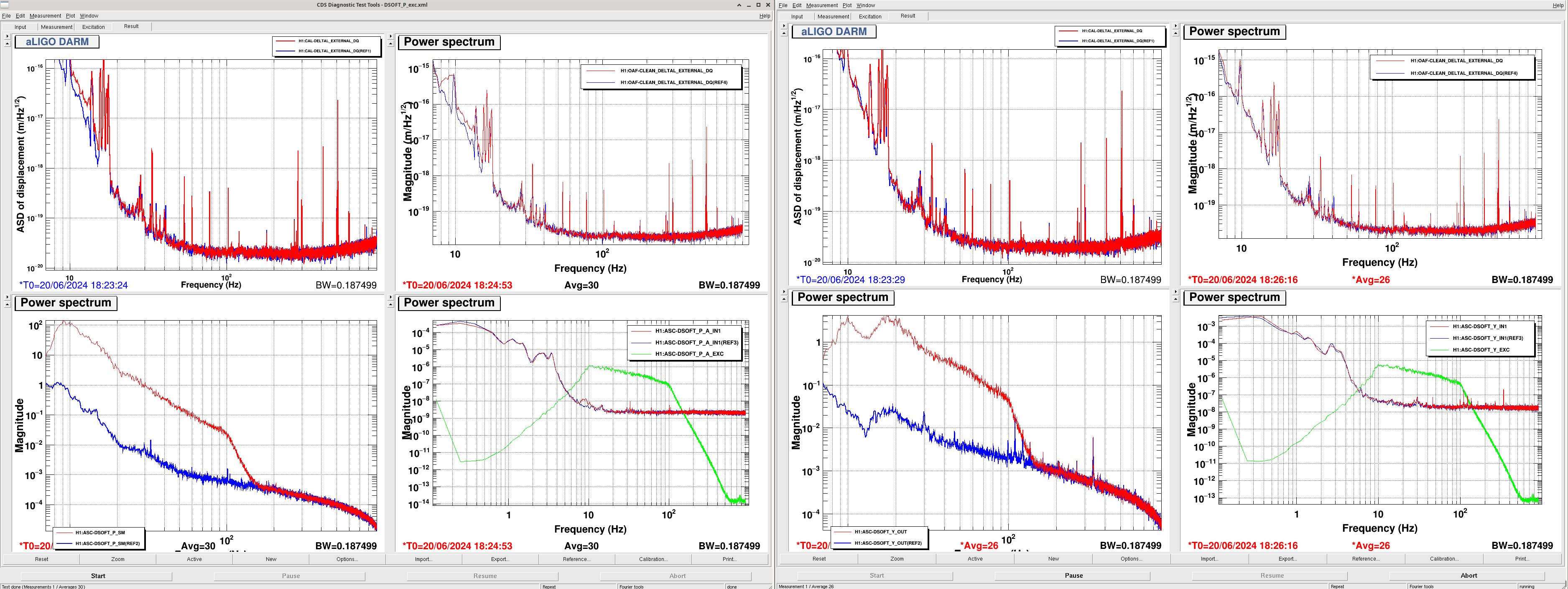
- ASC: CHARD dominates the ASC noise budget and is much worse than plot in December, CHARD P has spikey peaks 25-30Hz: same peaks as seen in jitter? DHARD is improved. Only see MICH ASC in the 301-32Hz peak.
Images attached to this report
Non-image files attached to this report
