Andrei, Sheila
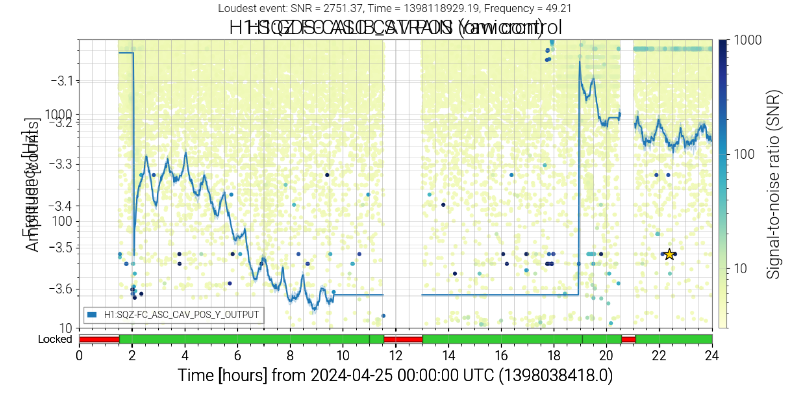
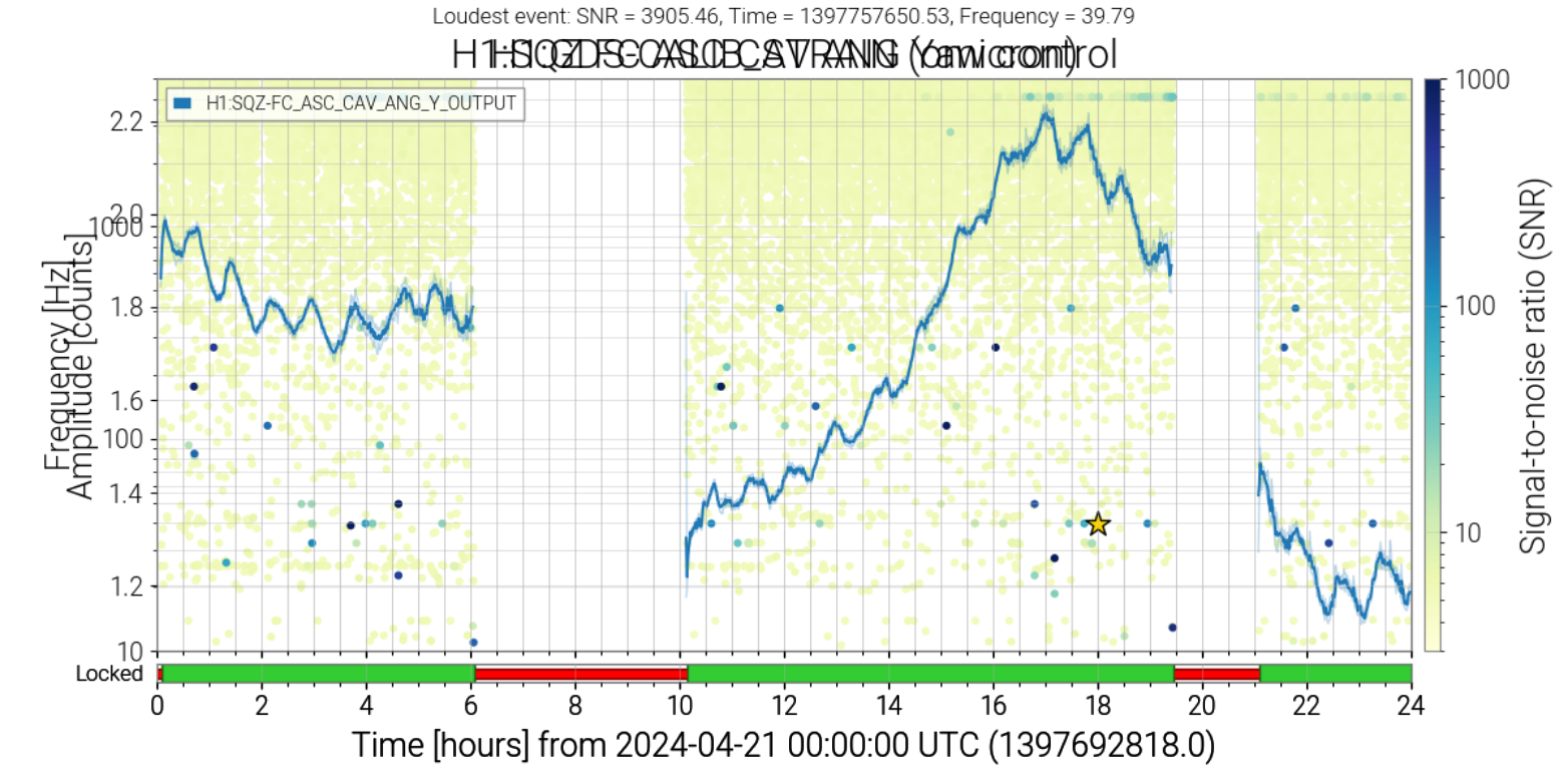
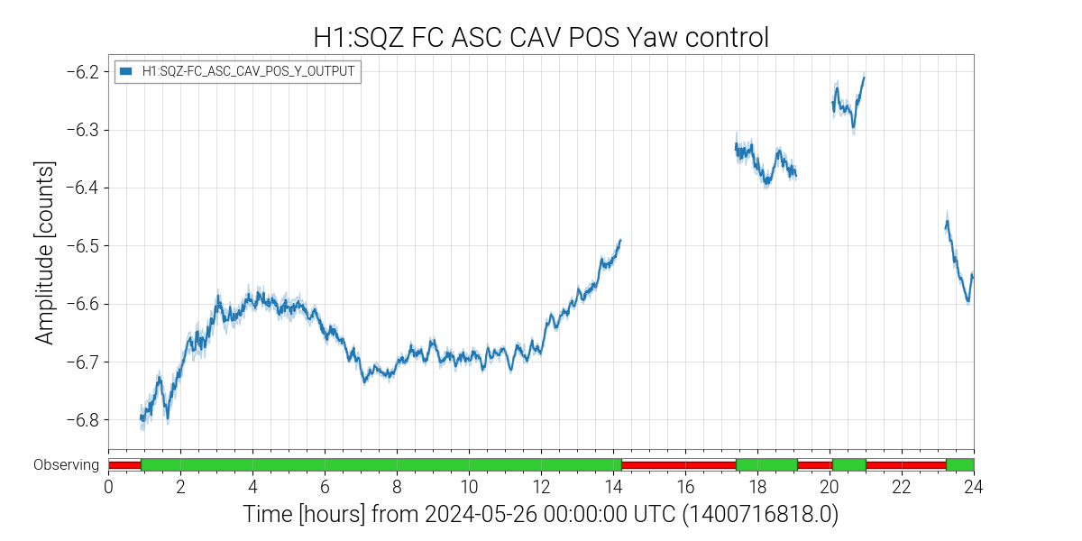
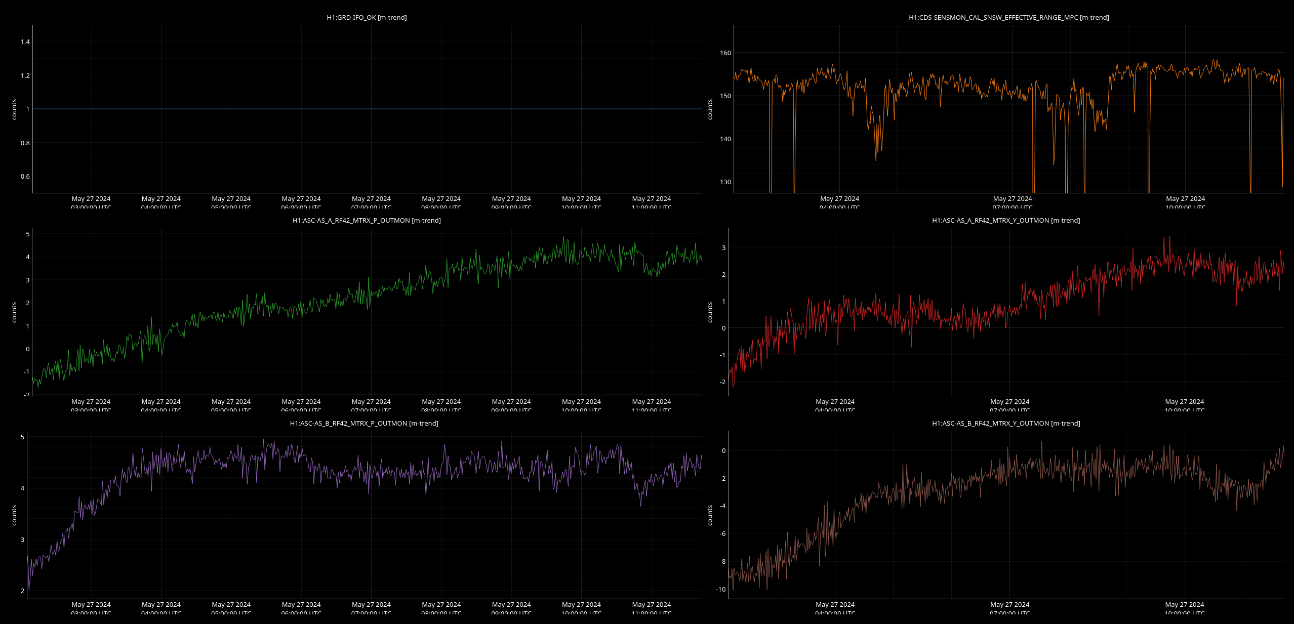
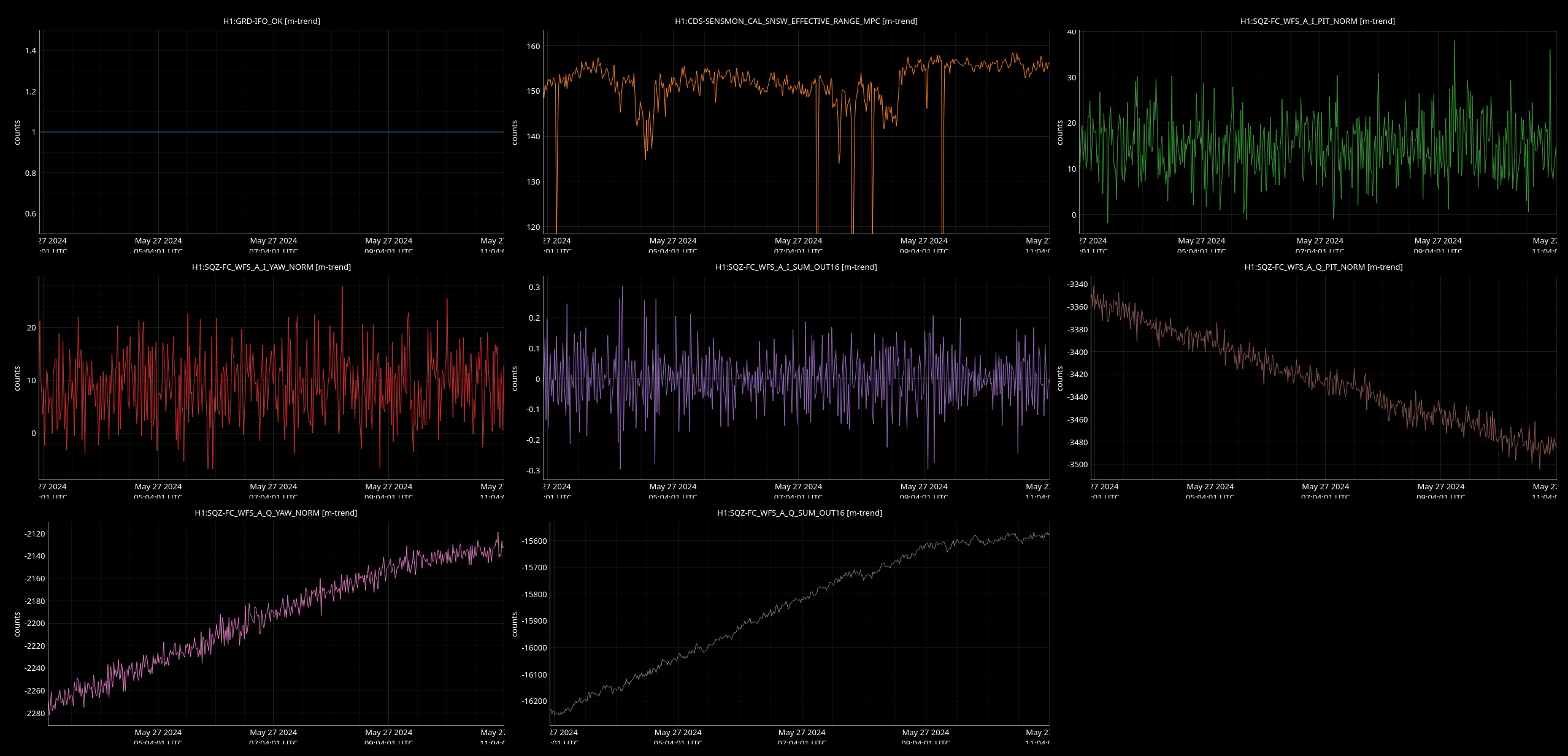
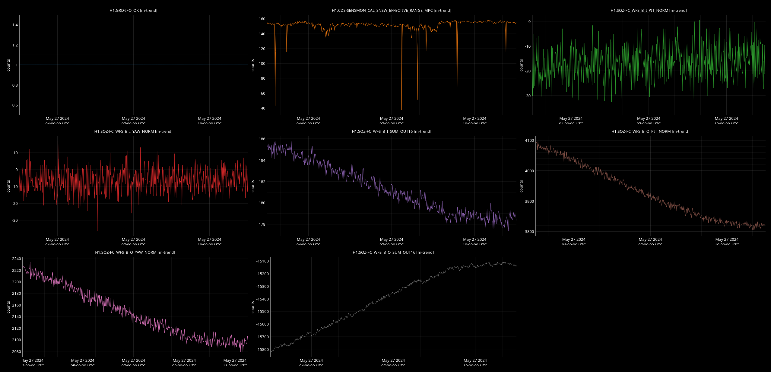
We've analyzed the time-traces of the effective range (H1:CDS-SENSMON_CAL_SNSW_EFFECTIVE_RANGE_MPC) along with the alignment channels FC_WFC_A(B) and AS_A(B)_RF42 (see attached figures). We found no observable dependance between those.
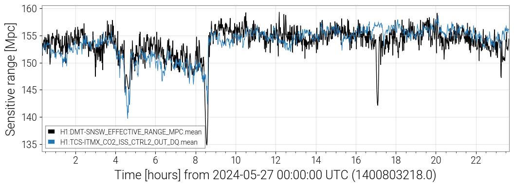
During the time period being investigated in this alog on May 27, LASSO flags H1:TCS-ITMX_CO2_ISS_CTRL2_OUT_DQ as strongly correlated with the range. This channel and other related channels have been flagged as highly correlated to the range in recent days, but this time period shows the strongest correlation.
- LASSO for segment beginning 2024-05-27 00:20:00 (correlation -0.43)
- LASSO for segment beginning 2024-05-24 19:21:48 (correlation -0.15)
- LASSO for segment beginning 2024-05-16 00:20:00 (correlation -0.33)
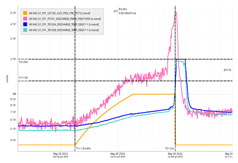
Jumps in this TCS channel correlate with range jumps, as shown in the attached comparison of the TCS and range trends on May 27.
Tagging TCS
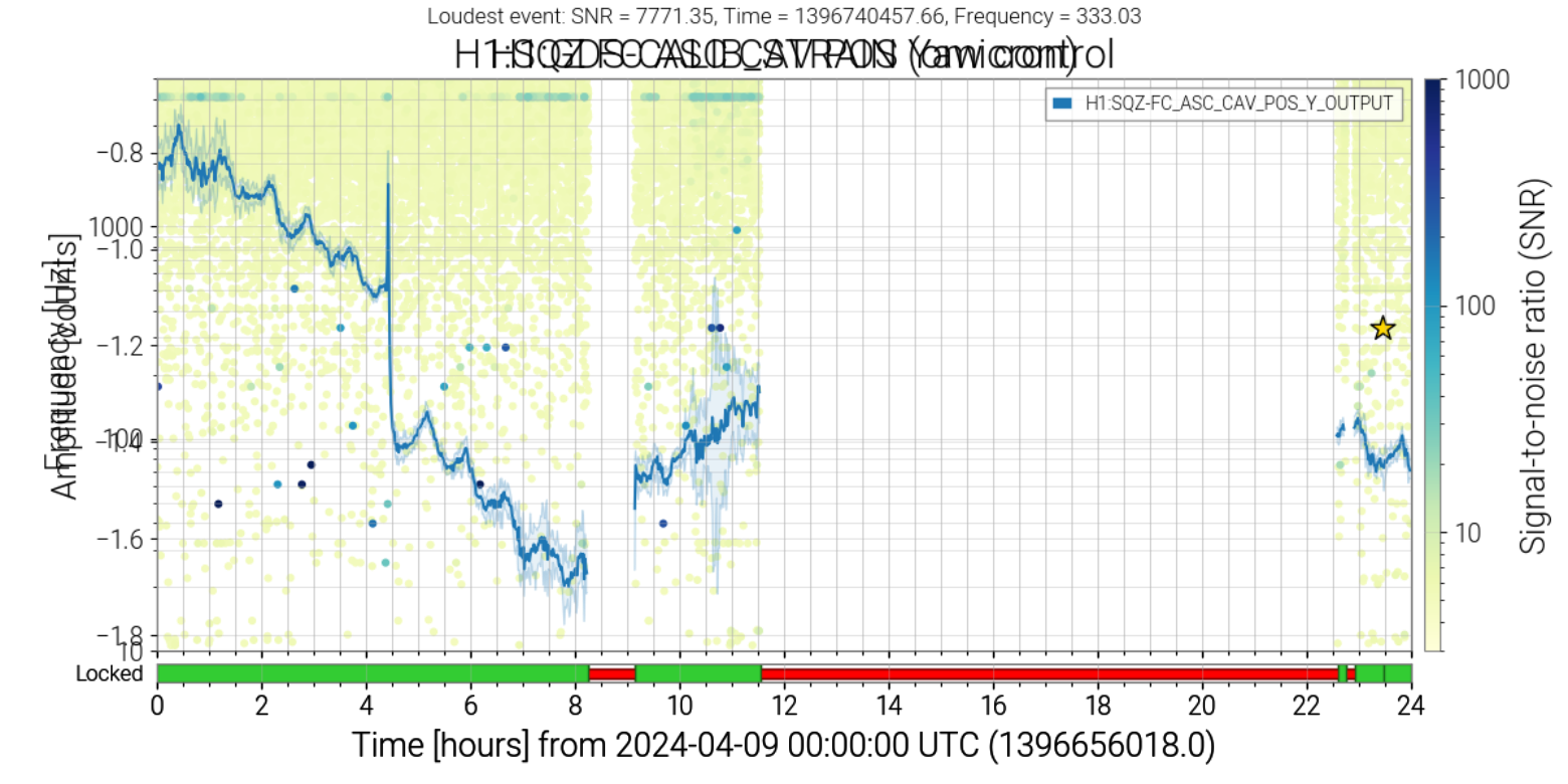
This TCSX ISS correlation is a bit odd since we aren't using the ISS and the AOM, I believe, is completely unplugged. That said, I looked at some of the channels in that system and there is some extra noise seen around the times Derek posted (see May 16th example). I wonder if this points to a larger grounding issue or some other electrical problem that is seen more broadly.
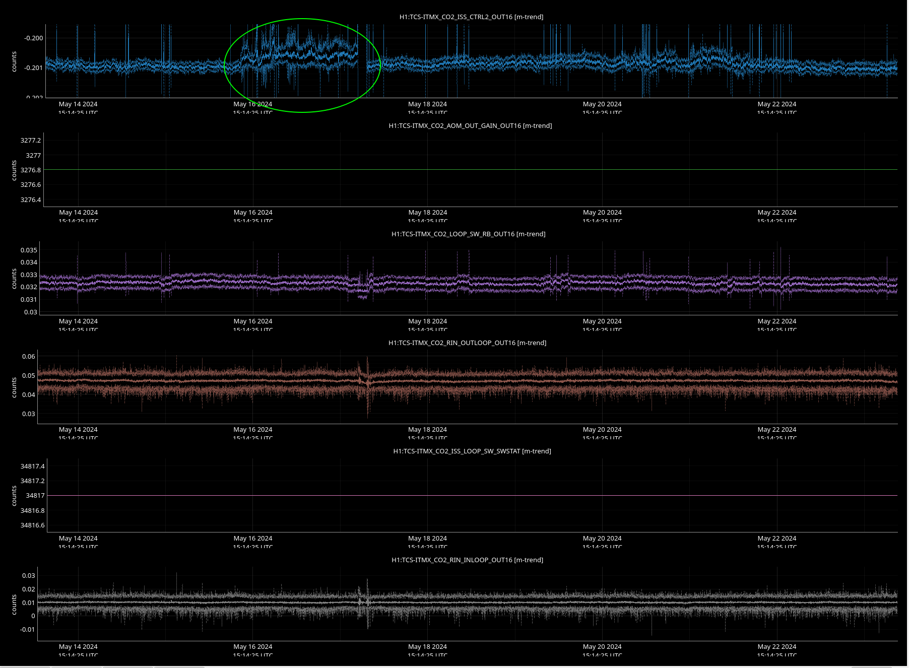
These range fluctuations that we think are related to the squeezer started (I think) on May 16th: 77869
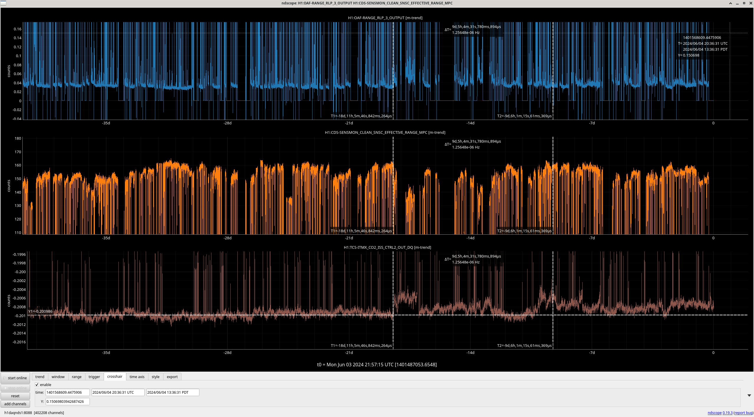
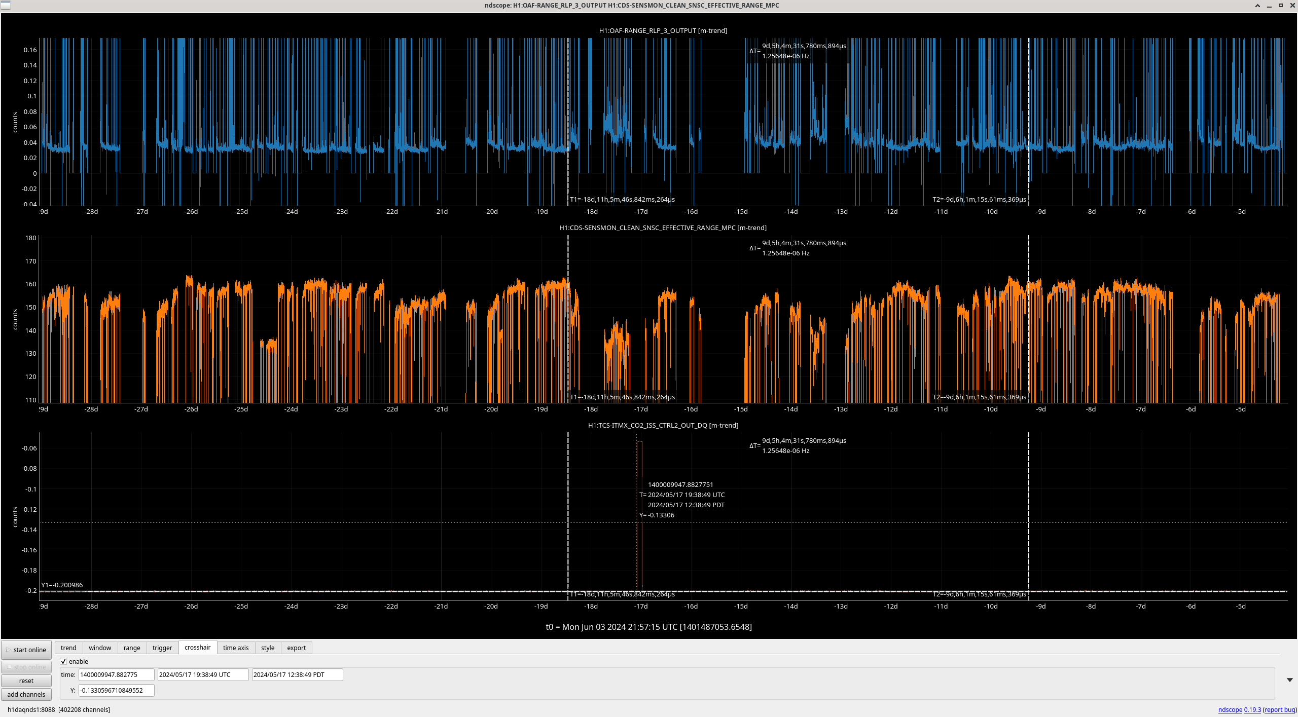
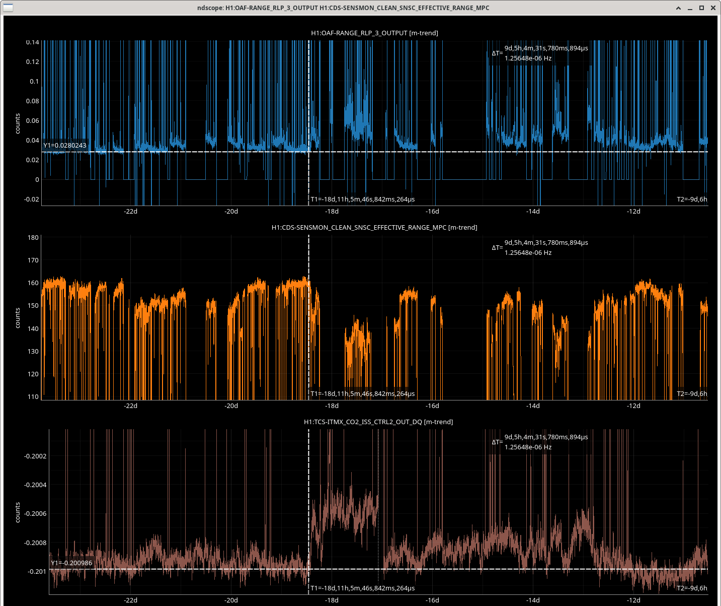
The first time cursor in the attached screeshot shows that range drip which I thought was traffic related at the time. Looking at the long term trend of this CO2 ISS control signal, there is a chance in charachter at this time, with more drifts in the signal level since. The second screenshot shows that this channel had a large jump on May 17th around 20:04-22:33 UTC.
There is a DARM BLRMS that may be more useful for tracking this noise than just looking at range, H1:OAF-RANGE_RLP_3_OUTPUT. (third screenshot shows this also had a change point and drifts more since May 16th.)