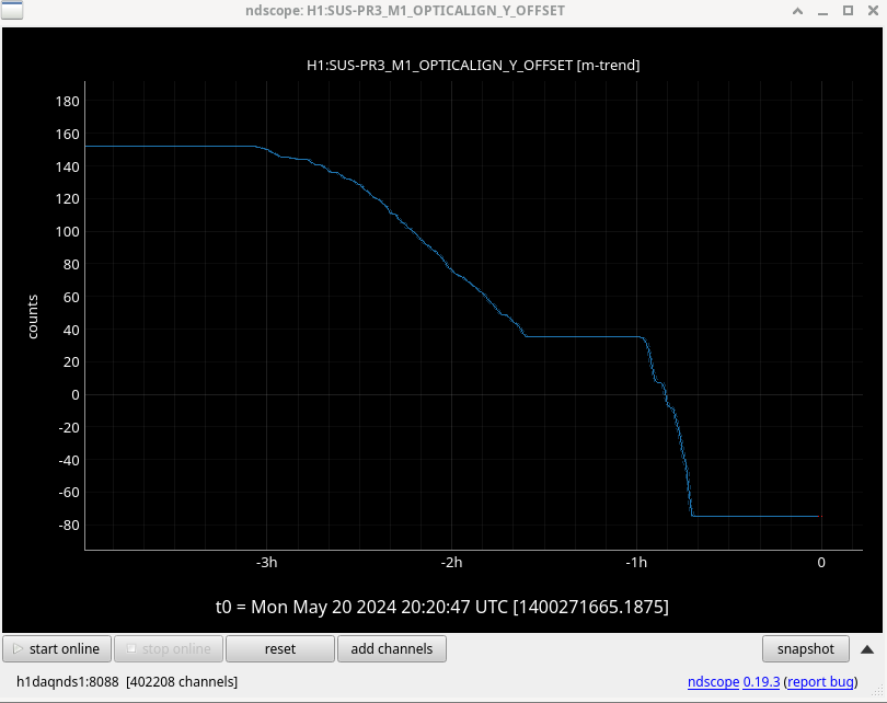
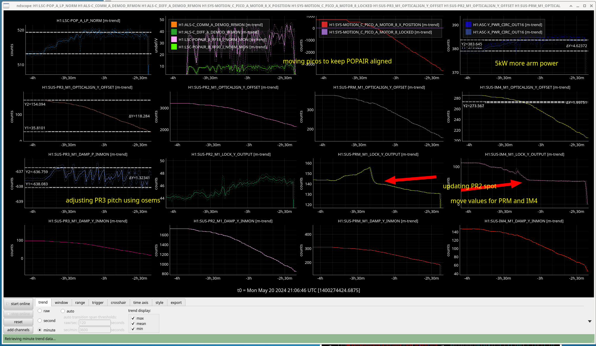
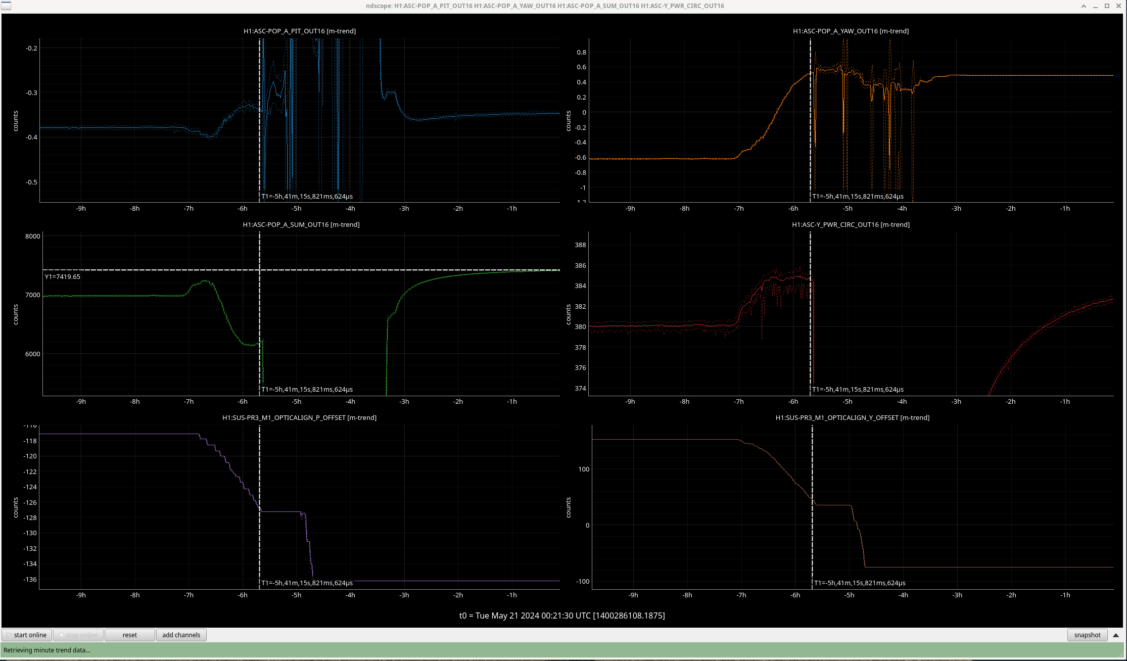
Now that the wind has (mostly) calmed down, and we're pretty confident that the increased low frequency noise late last week was due to (not yet understood, intermittent) squeezer-related noise, Sheila and I moved PR3 to get closer to center on PR2. Mostly we were moving in yaw, but then we occassionally moved PR3 pitch to counter-act the pitch shift that was happening due to cross-coupling. We were making these PR3 pit moves primarily according to the PR3 top mass OSEMs.
While we were moving in yaw using the ISC_LOCK guardian state PR2_spot_move, Sheila noted that the scaling of the slider moves for PR2, PRM, IM4 in response to a PR3 move weren't quite right, since the ASC had to respond a bit. So, she re-calculated and tuned the scaling factors in that guardian state, and now the ASC responds much less (indicating that all the sliders are moving close to the correct values in response to a PR3 move).
Overall, we moved PR3 yaw slider from +152.4 to -74.9. We did about the first half of the move in full lock, gaining about 1% increase in POP_A_LF and also about 1% increase in arm cavity buildups. We had gone maybe 1/4 of our total for today, and we stopped gaining in overall buildups, which makes sense if we got to a point where we're no longer really clipping (and so moving farther isn't un-clipping us more). I think I started going too fast (and didn't pause to use the pico motor), and we lost lock, so then we did the second half with just the green arms locked, and pico-ing to keep the COMM beatnote high.
We redid initial alignment, and are on our way back to lock. We'll post more details on this morning's work, but this is just a quick alog so I don't forget, while I go off to another meeting.
Before we did any work today, we had two quiet times.
- After A2L was run, but before any alignment changes: from 16:53:30 UTC to 17:07:00 UTC.
- After A2L was run, before any alignment changes, but with No SQZ: from 17:08:00 UTC to 17:13:00 UTC.
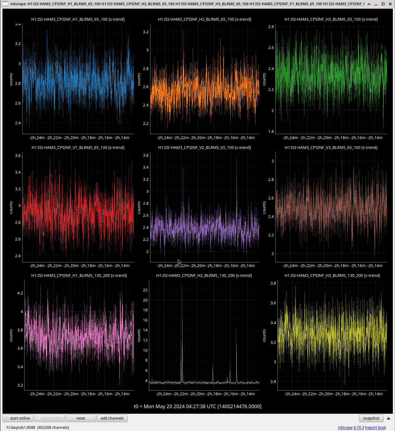
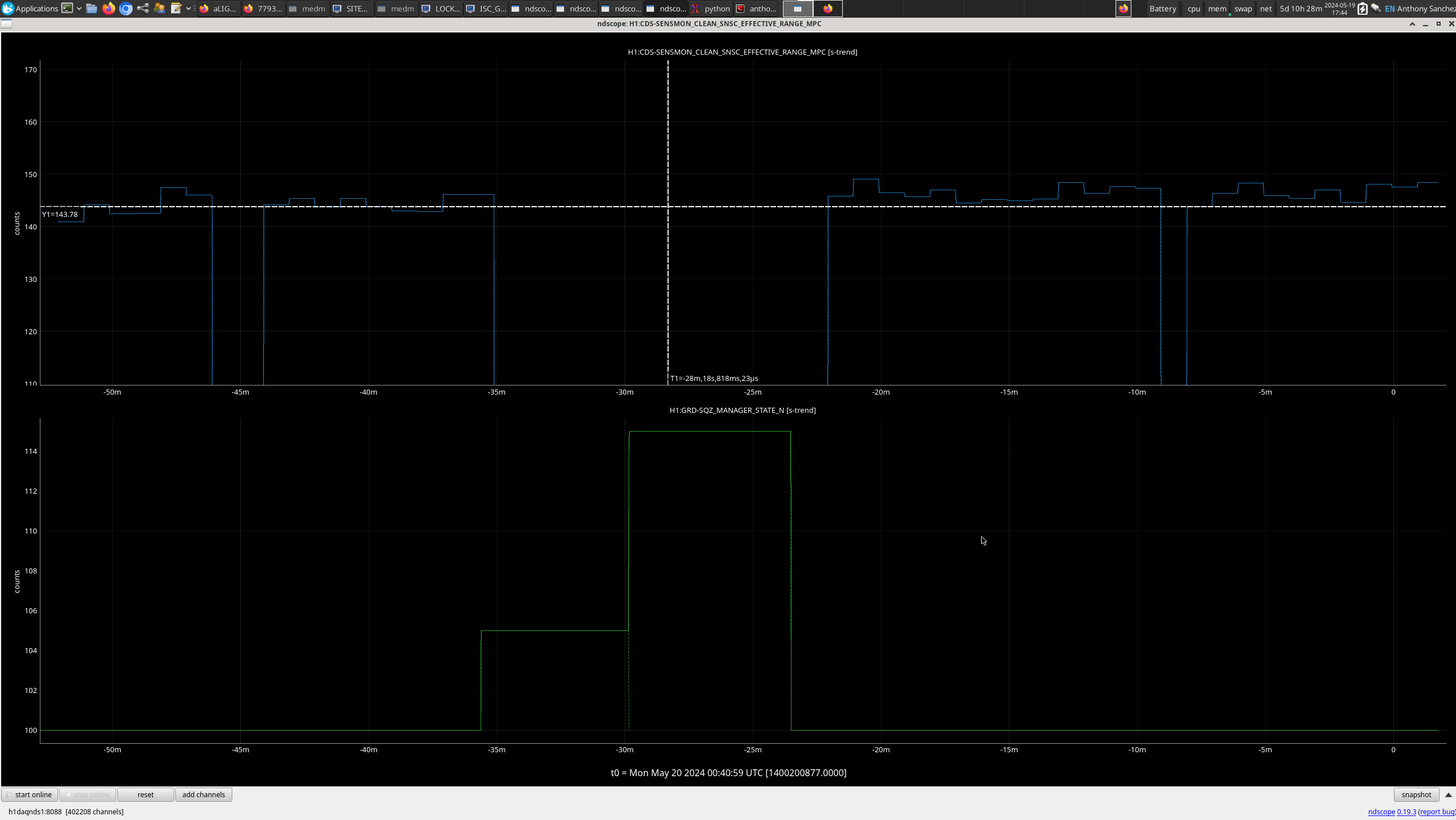
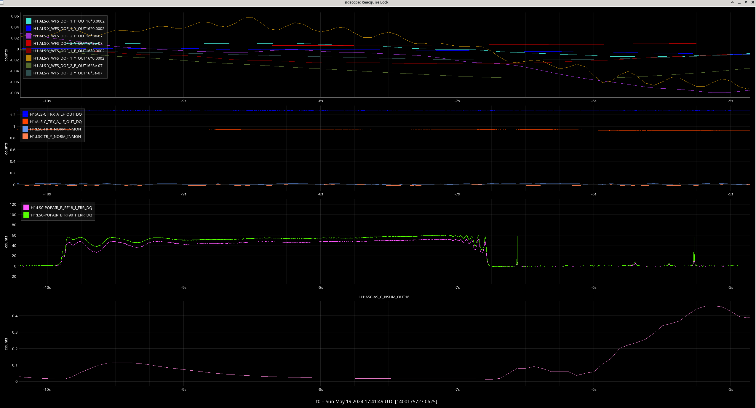
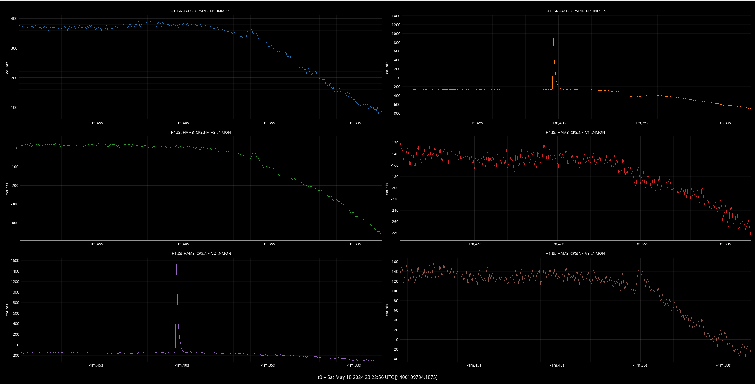
Attached in an annotated screenshot showing some trends as we moved PR3 in lock.
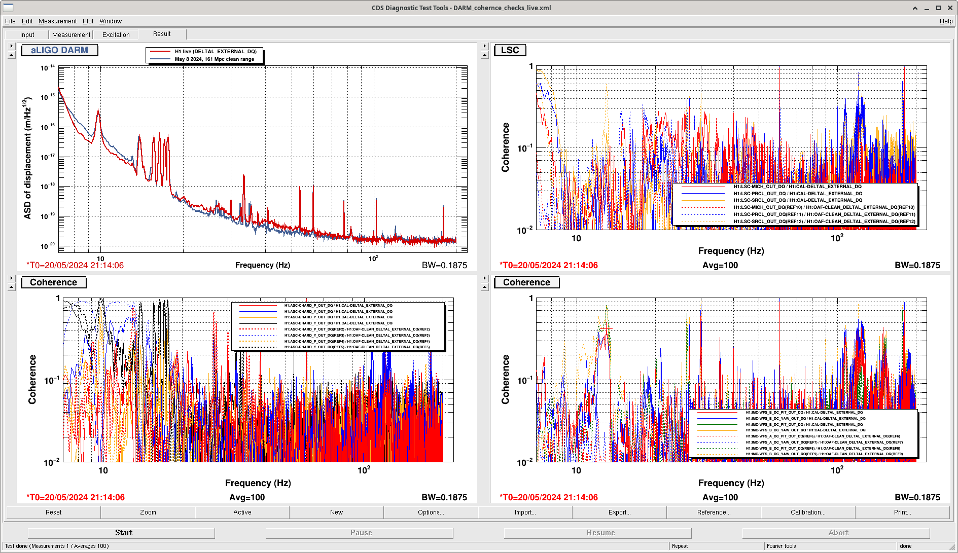
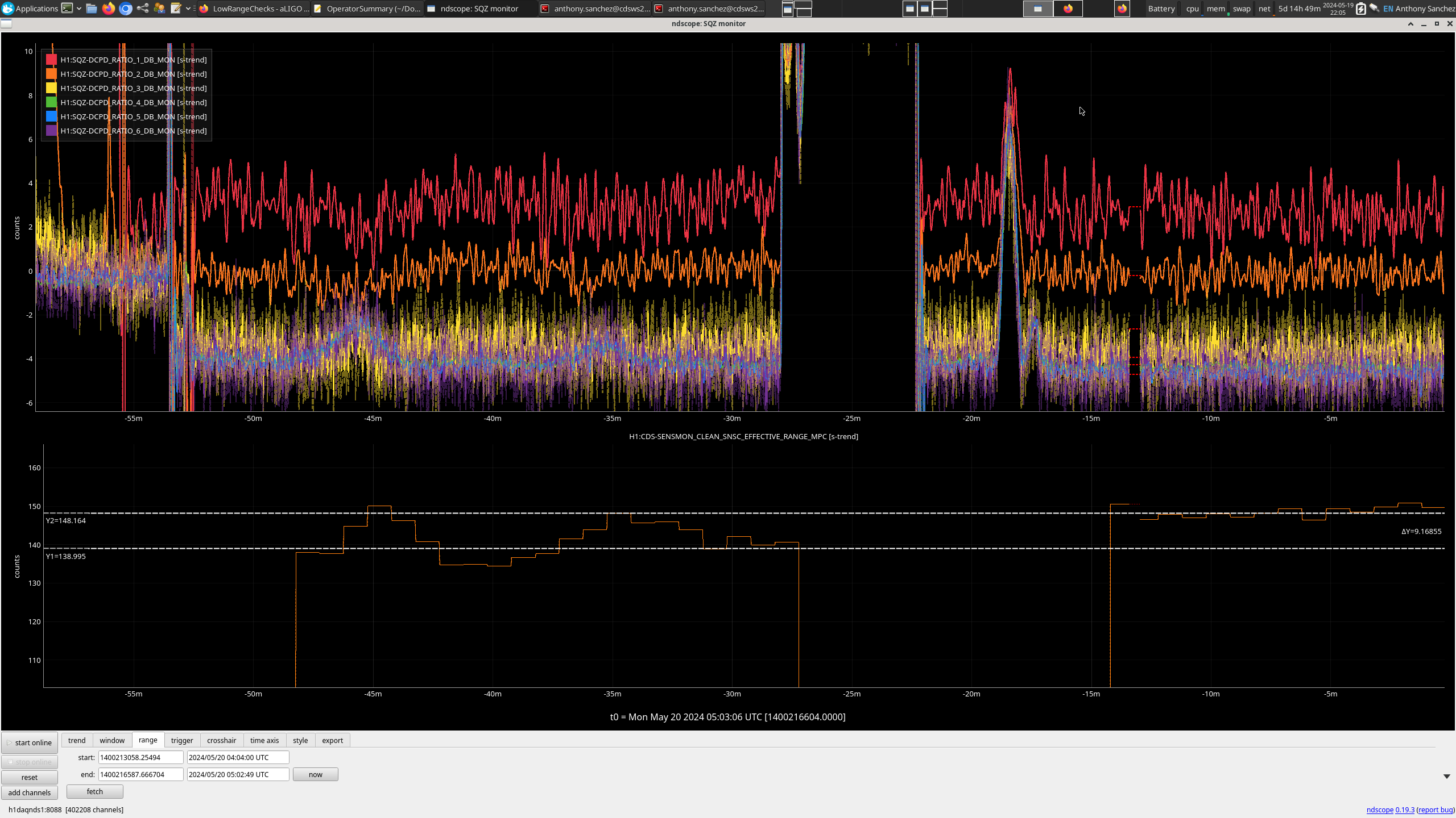
We are now back in NLN, and it looks like we need to adjust the MICH FF. We will wait for the IFO to thermalize a few hours before doing this. The squeezing is also not good right now, but changing rapidly during thermalization.
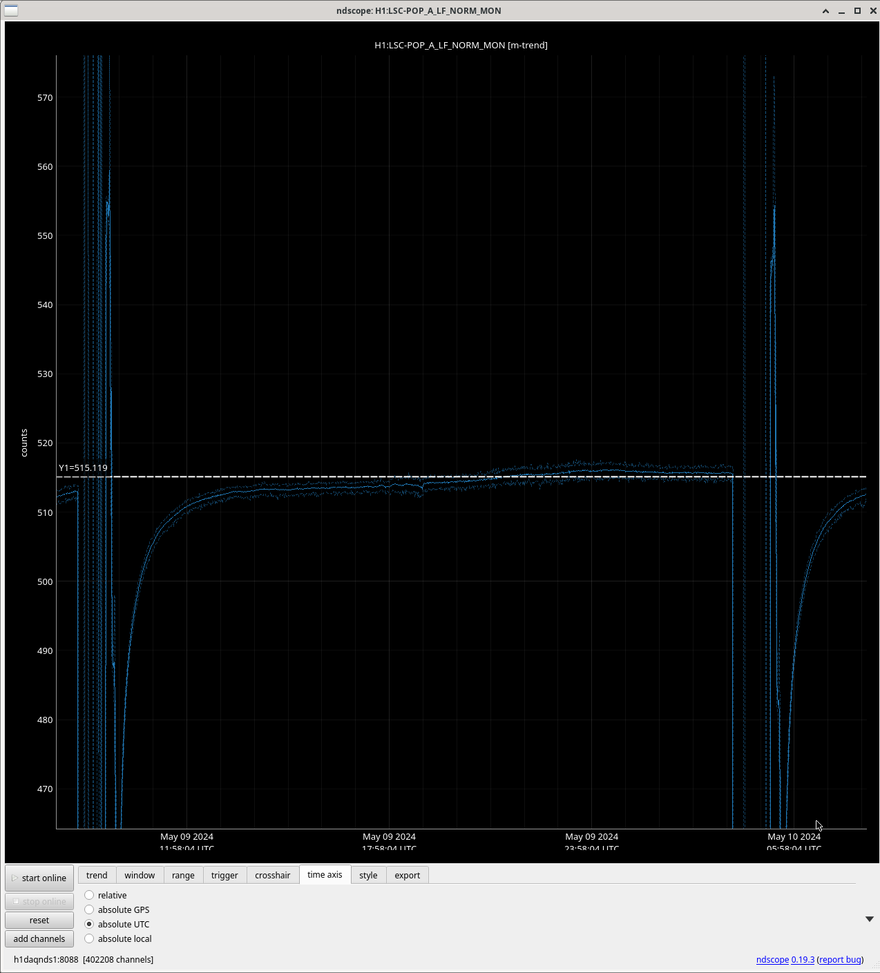
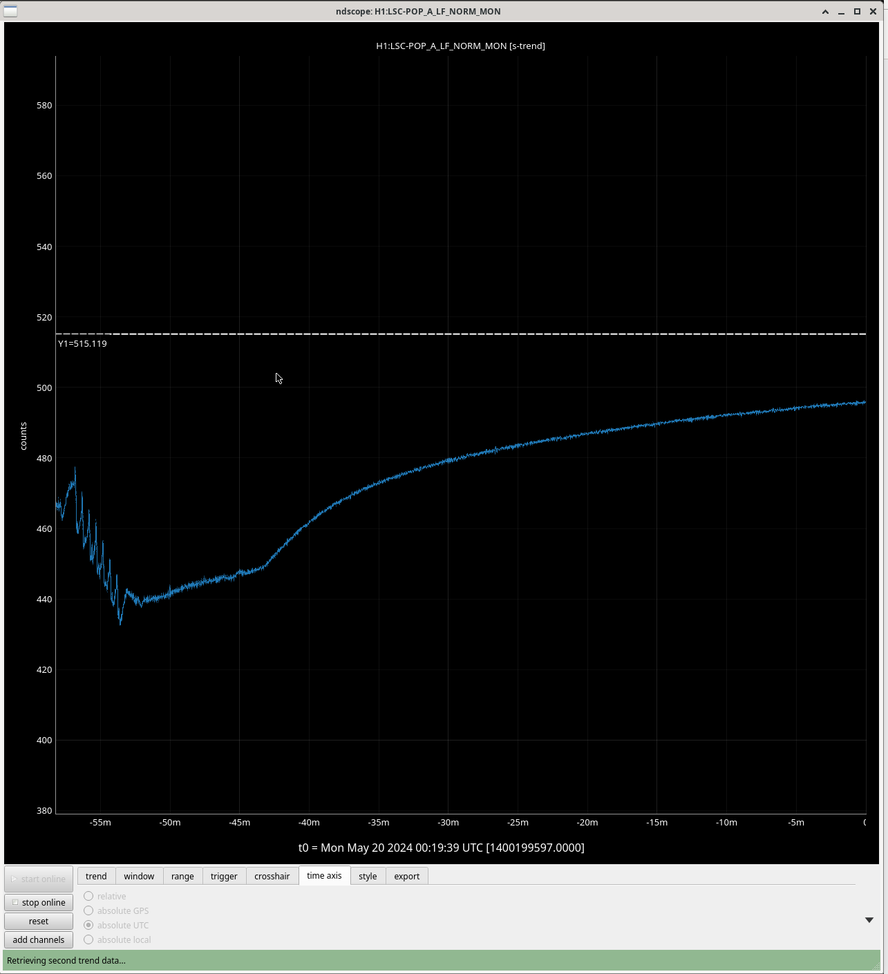
The second screenshot shows the same trend as the first, but with the POP QPD added. The in lock move of -118 urad in PR3 yaw moved the beam from -0.6 to +0.6 in yaw, while the second out of lock move -112 urad seems to have not moved the spot on POP. I don't understand why that would be, but it probably makes sense to pico POP before we move another 250urad (if we think we need to).
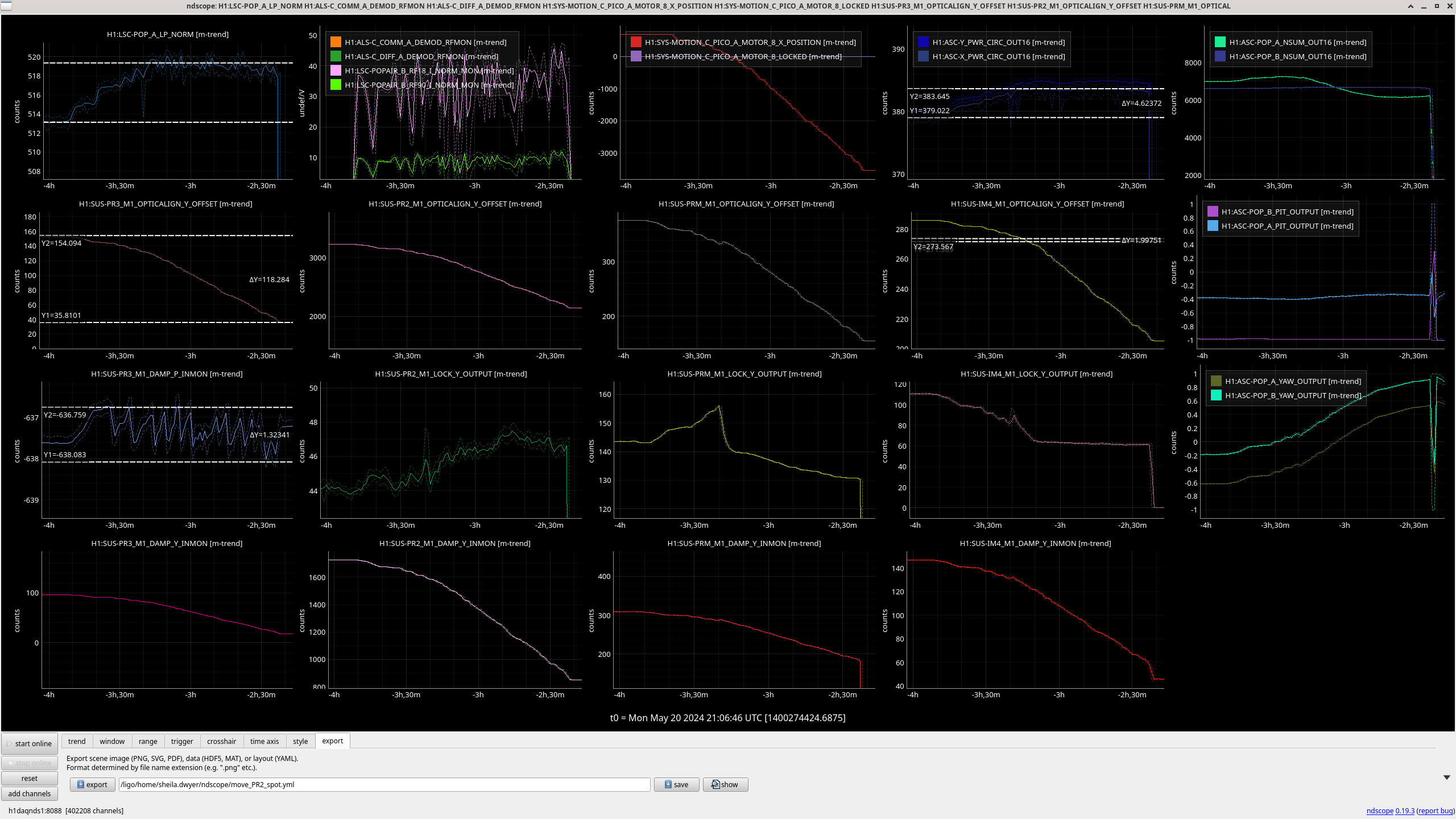
Adding some more data to the confusion over why POP QPD didn't see a move after our out-of-lock PR3 move, I also see that this new lock has the NSUM on POP_A_QPD thermalizing to a higher value than we had earlier, but the yaw value of the QPD seems to still be in about the same place as it was when we lost lock halfway through todays PR3 move.

