corey.gray@LIGO.ORG - posted 16:21, Thursday 16 May 2024 (77867)
Thurs DAY Ops Summary
TITLE: 05/16 Day Shift: 1430-2330 UTC (0730-1630 PST), all times posted in UTC
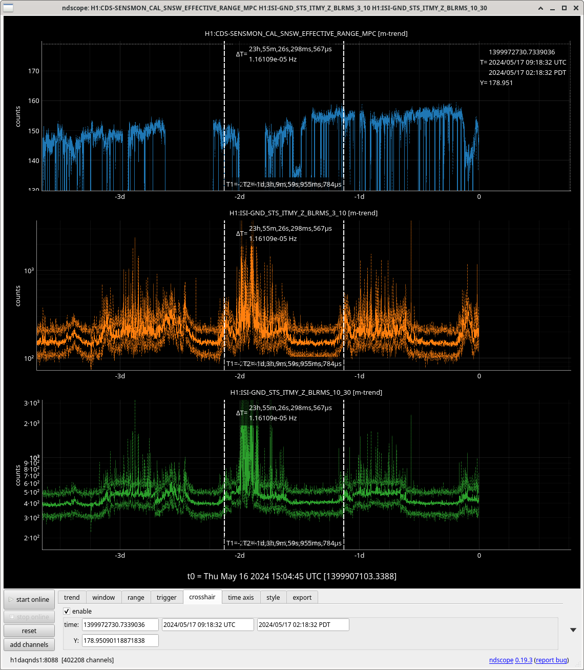
STATE of H1: Observing at 144Mpc
INCOMING OPERATOR: TJ
SHIFT SUMMARY:
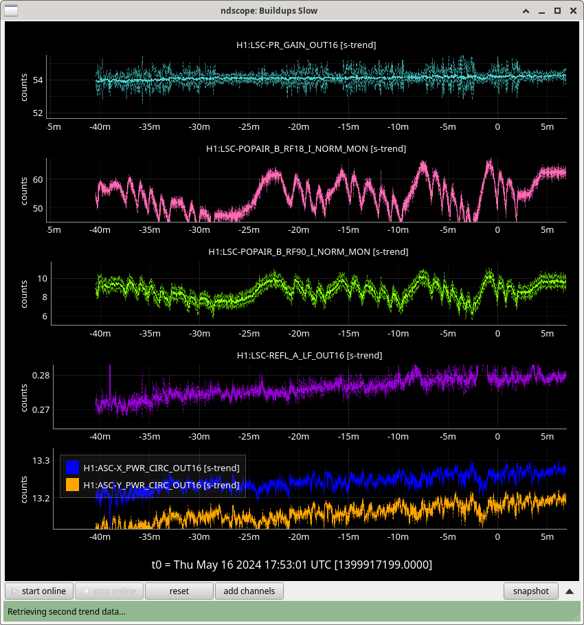
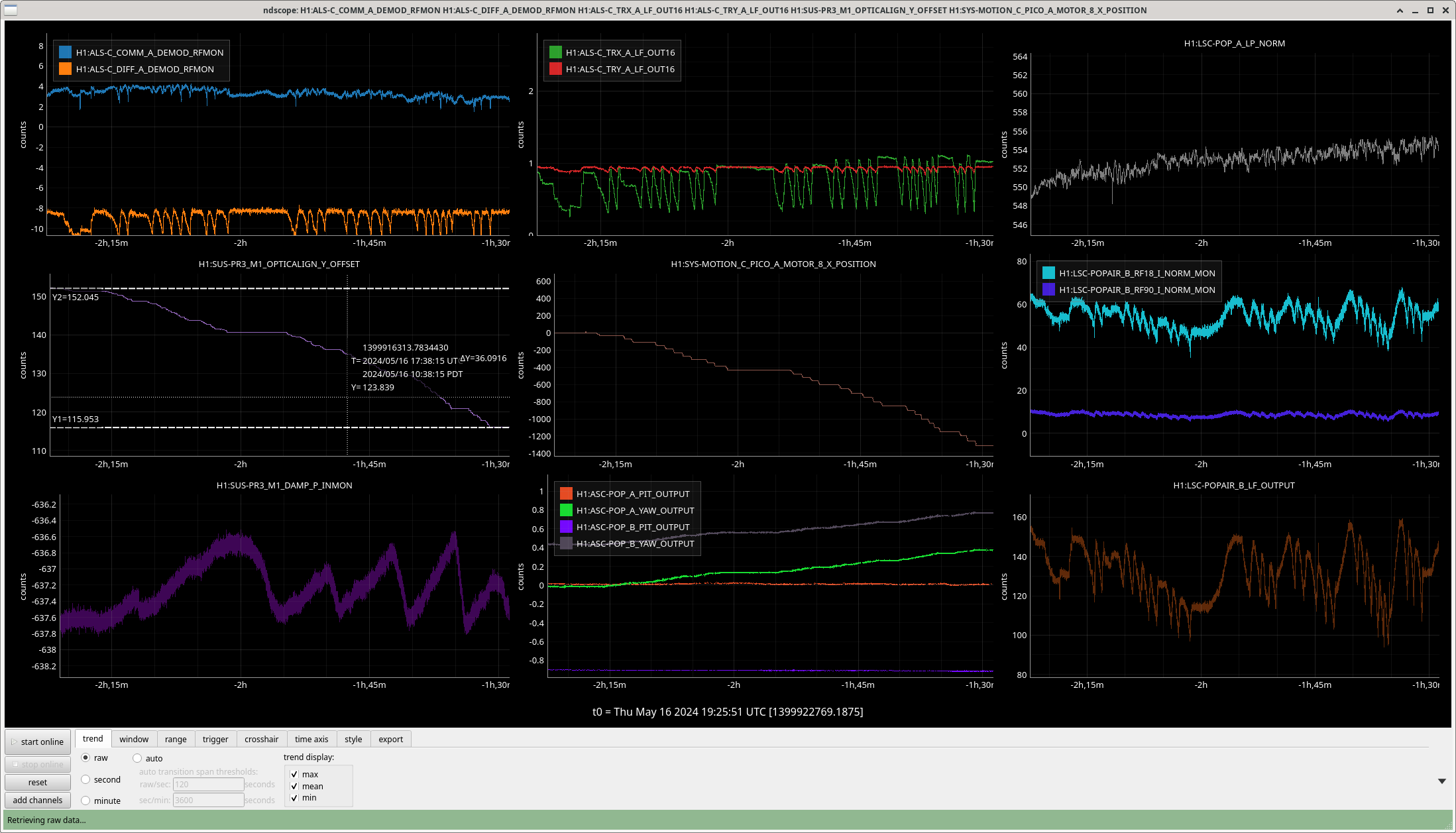
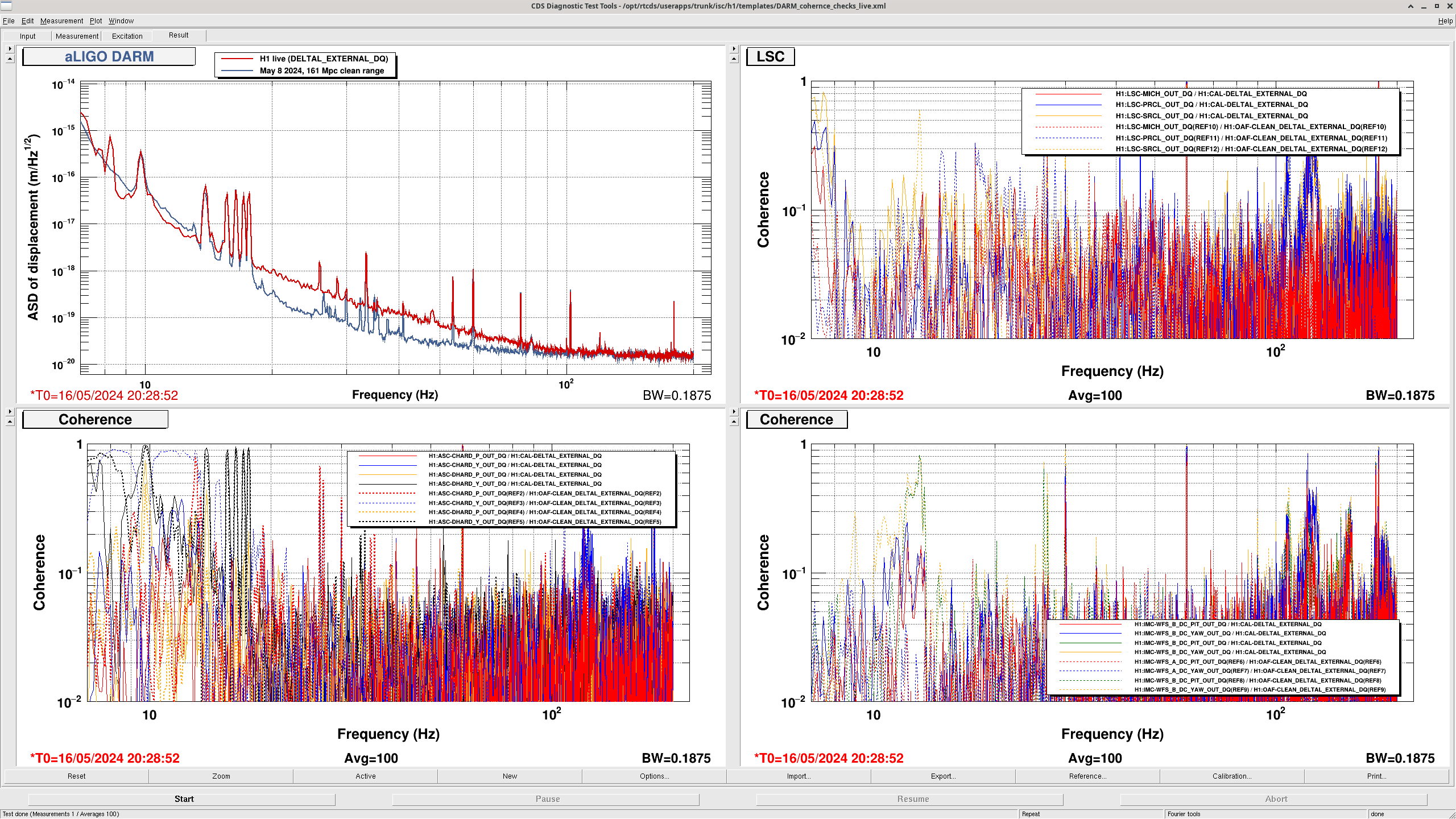
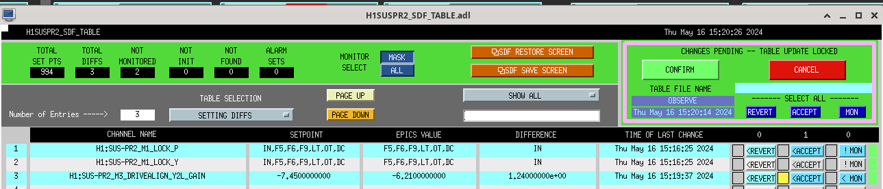
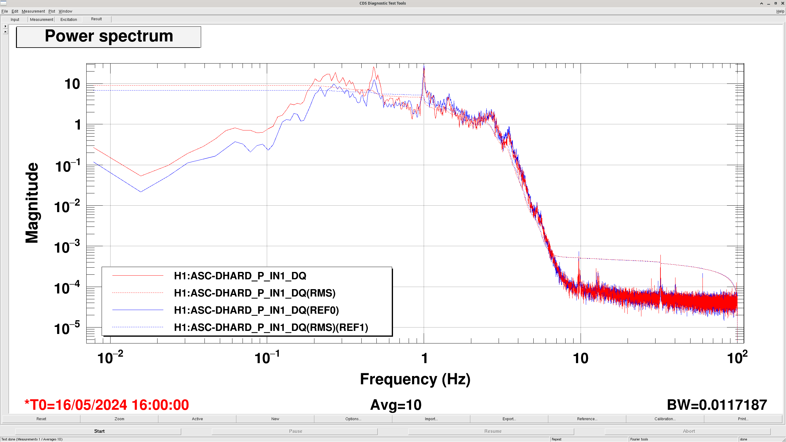
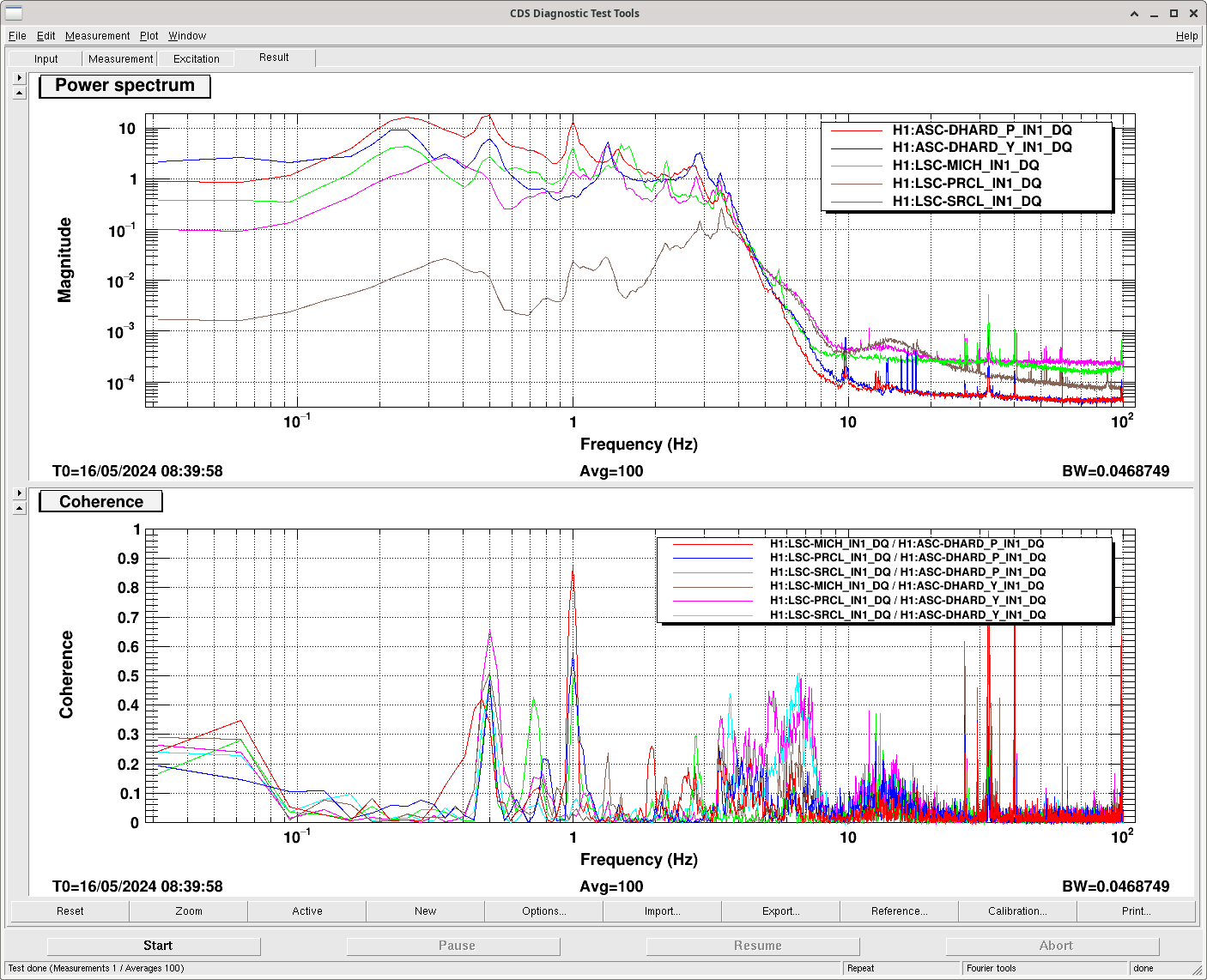
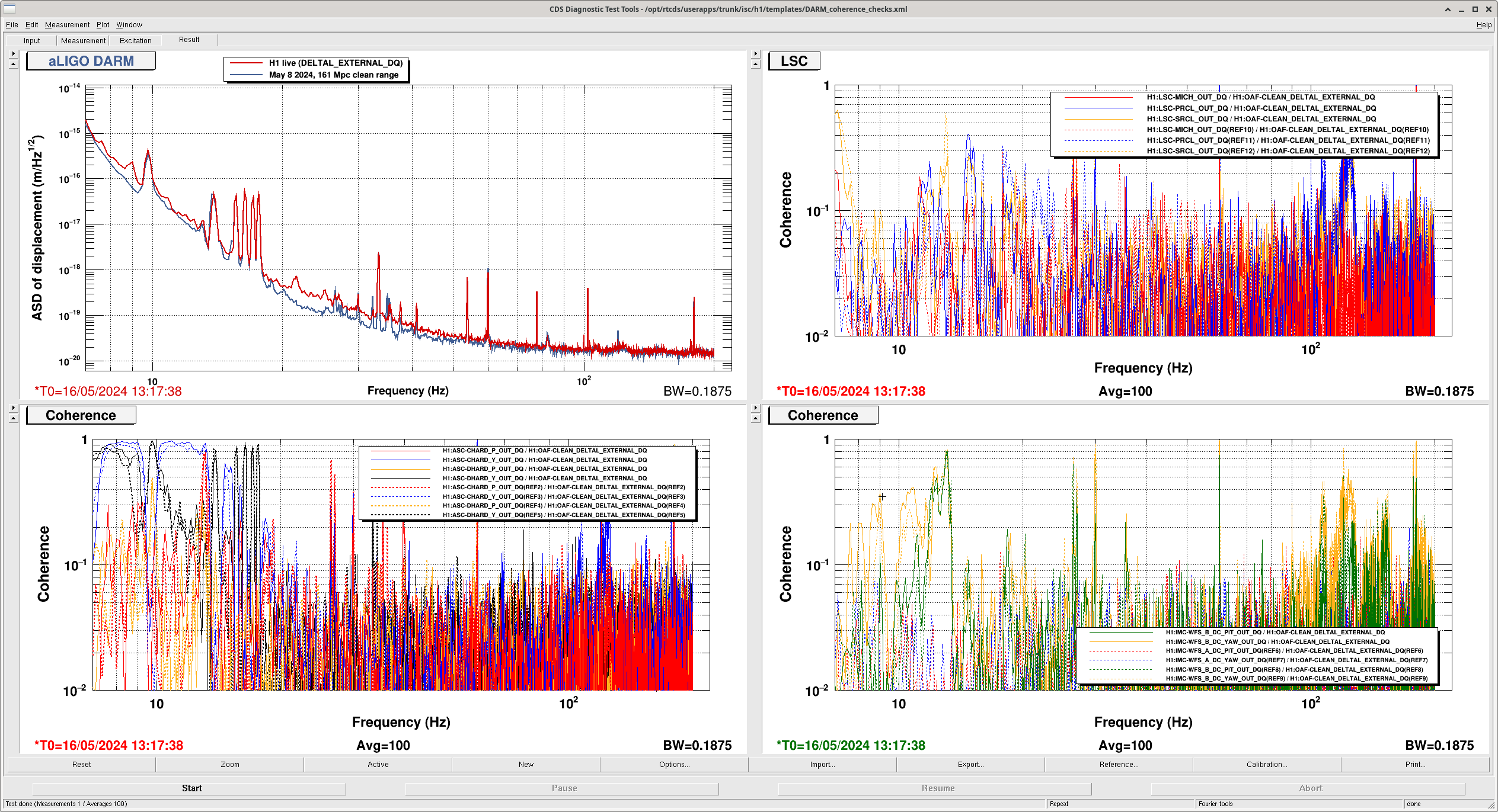
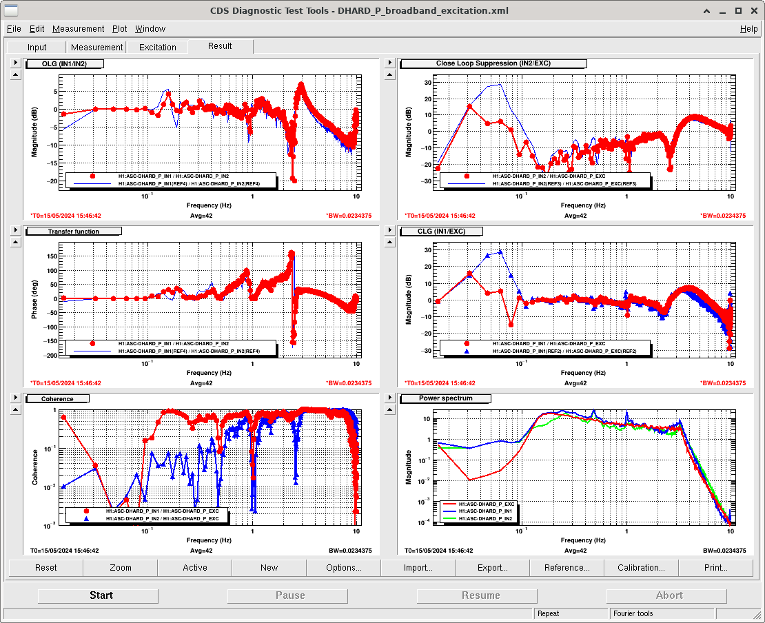
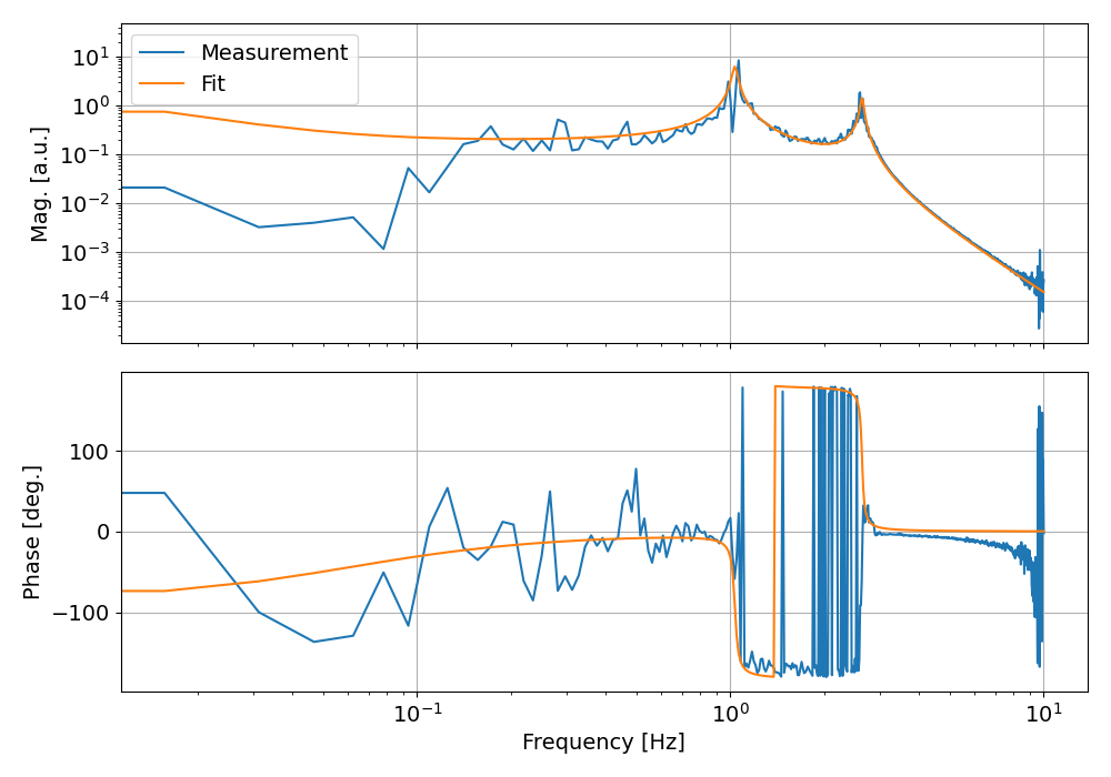
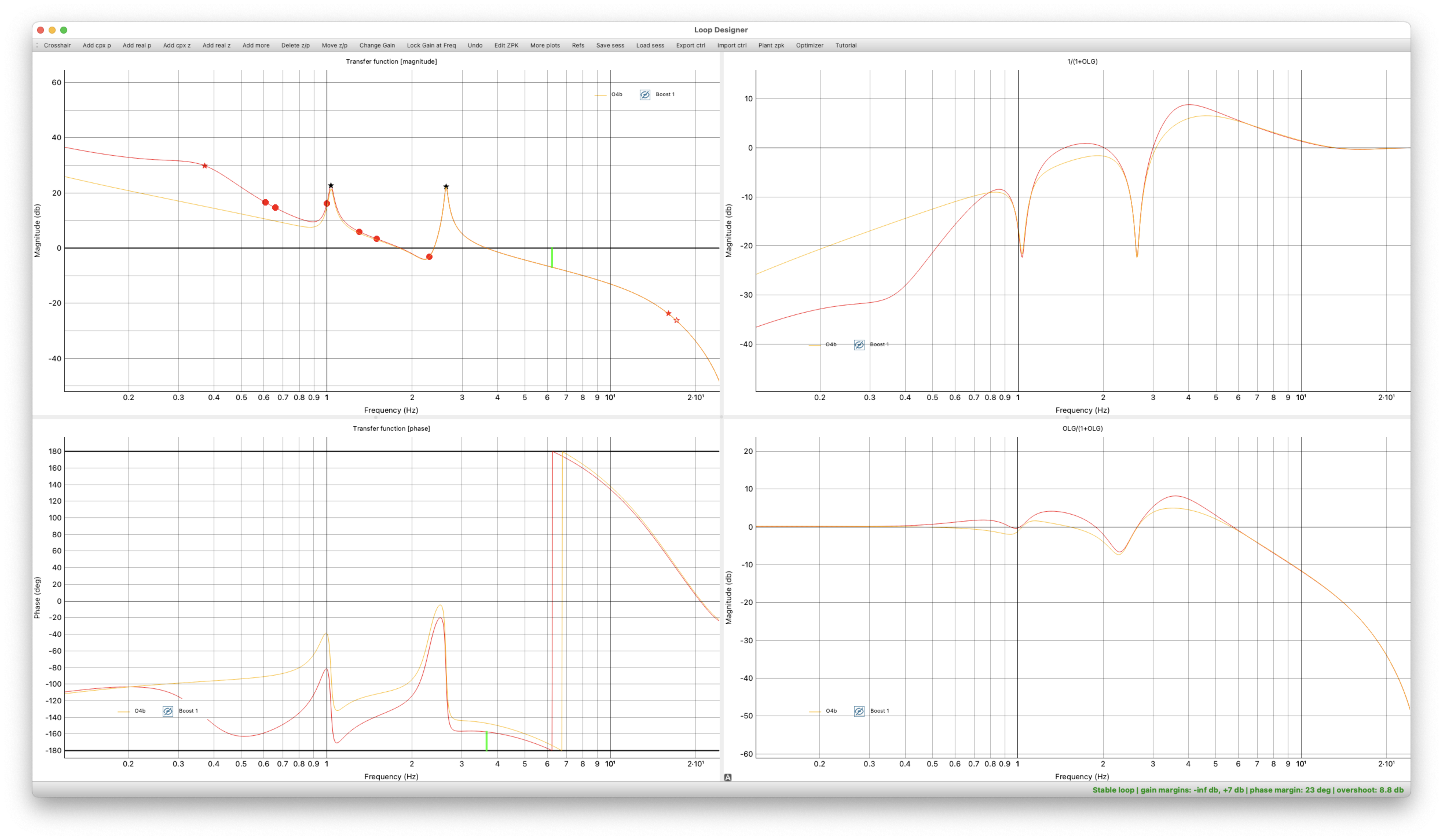
Today was primarily a commissioning day (with 90min of OBSERVING at the start of the shift). PR3 was moved to a new spot along with some picomotor moves (Sheila/Jenne/Menyo). Attempting to keep this configuration for the night (see Sheila's alog) to continue commissioning tomorrow to see if this new configuration can improve the overall range for H1 tomorrow---Jenne gave TJ a summary of this state of H1 for tonight.
LOG:
- 1444-1506 Optics Lab cleaning/checks (karen)
- 1459 Received "Hanford Emergency Information" automated phone call for EXCERCISE of a Take Cover/Shelter-In-Place/Simulate for the 200W Area. We are NOT participating in this exercise; I responded with a receipt of the messsage. (Received a similar message at 1511 & 1621, which listed LIGO and others which was different from 1st call....but they said it's an EXERCISE and for 200W; Richard said we can disregard and we are not particpating.)
- 1510-1513 Quick peek in LVEA (richard,sheila)
- 1539-1637 wood shop cleaning (karen)
- 1600 COMMISSIONING
- 1615 re-ran launch script for nuc33 again due to dtt crashing overnight.
- 1620 LOCKLOSS
- 1635 police exercises occurring (bubba phoned)
- 1647-1658 EY to check wifi (erik)
- 1652-1800 MY roof inspections (tyler/3-vehicles)
- 1800- Now MX
- 1927-1931 Wifi tests for MSR (erik)
- 1939 Different wifi checks at MX (erik)
- 2032-2036 Restoring HAM3 black glass (sheila)
- 2115-2117 Happened to see Trash truck approach LSB to access dumpster.
- 2215 LOCKLOSS----commissioners will keep unique alignment configuration and run an involved Initial Alignment.