Jennie W, Sheila, Matt Todd, Trent Gayer, Craig
Summary: Measured summing of QPDs on OMC and remeasured the sensing matrix and updated the input matrix for the OMC ASC. We also locked the OMC with no sidebands and took an OMC scan. The AS loops look good but we might need to check the summing of the QPDs offline as we weren't sure if the yaw quadrant summing of QPD B has the correct sign.
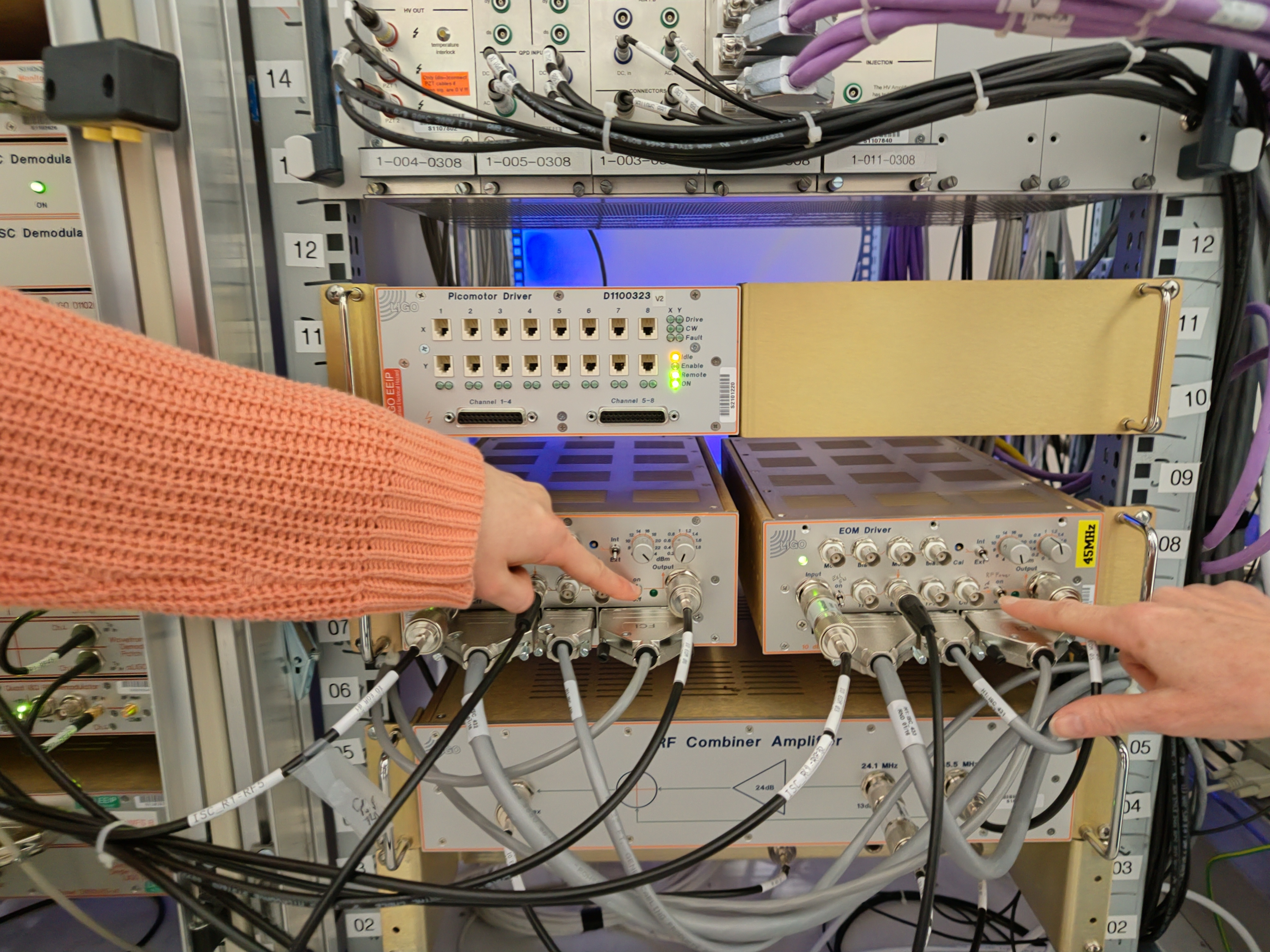
First we checked that the quadrants of the two OMC QPDs are summed the correct way.
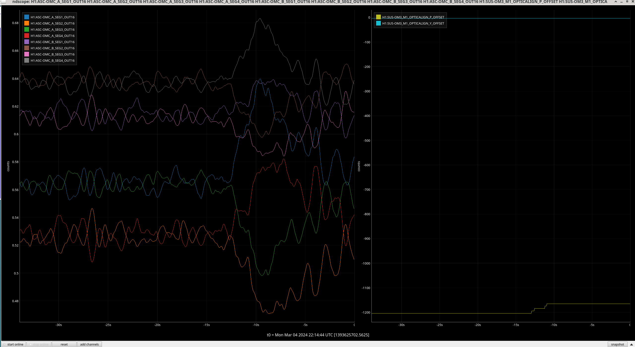
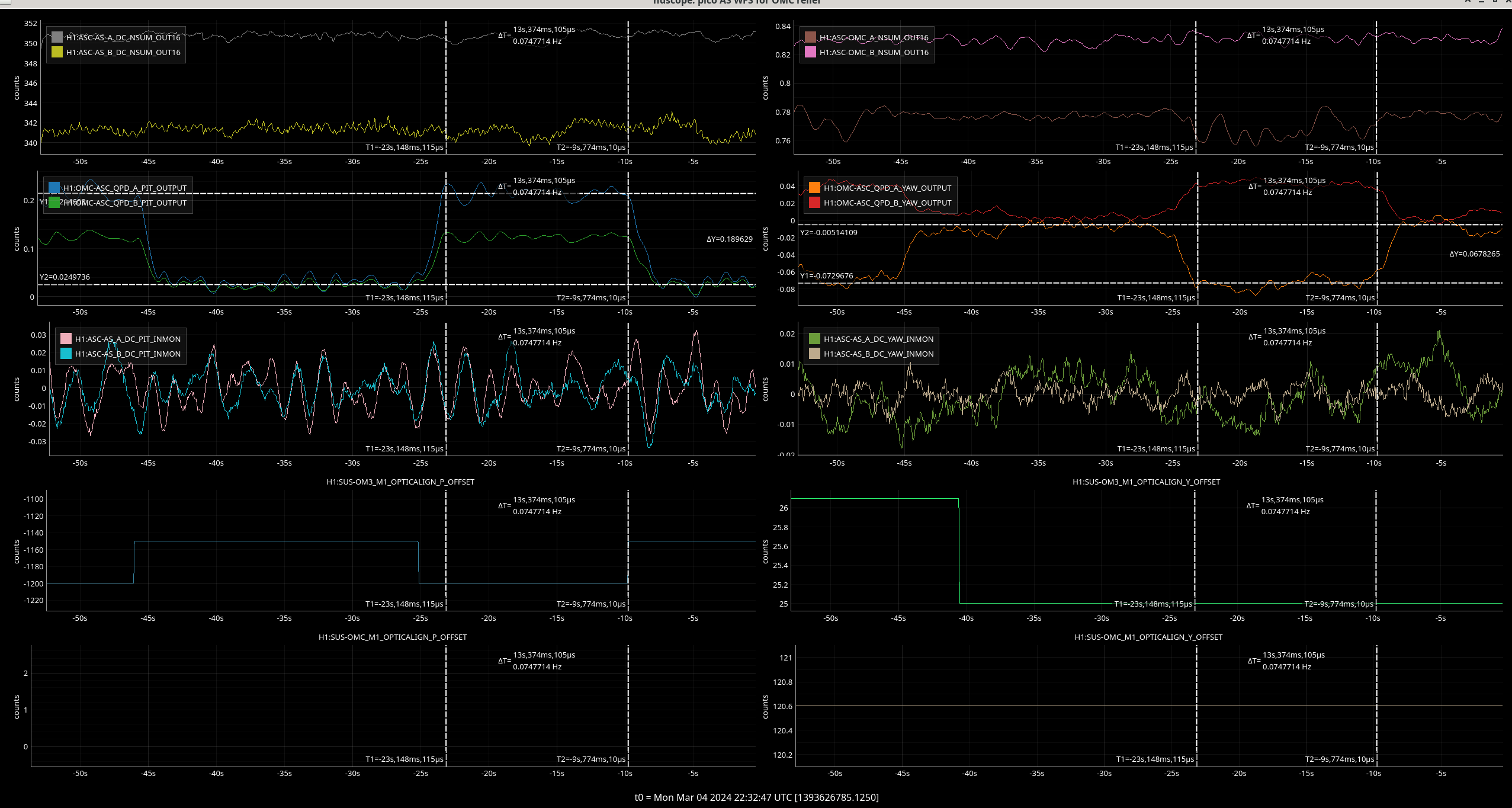
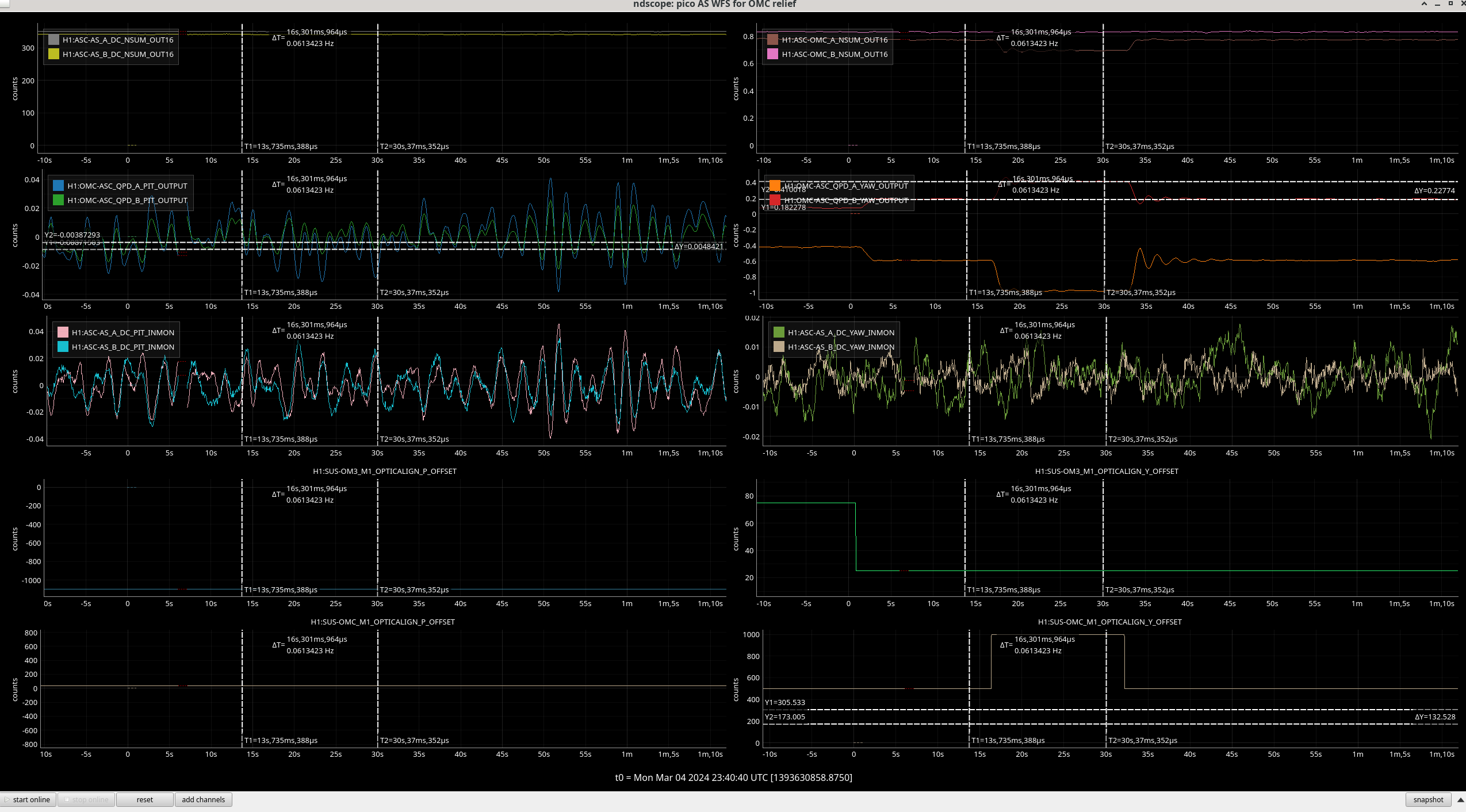
When OM3 pitch is stepped up, as in image 1:
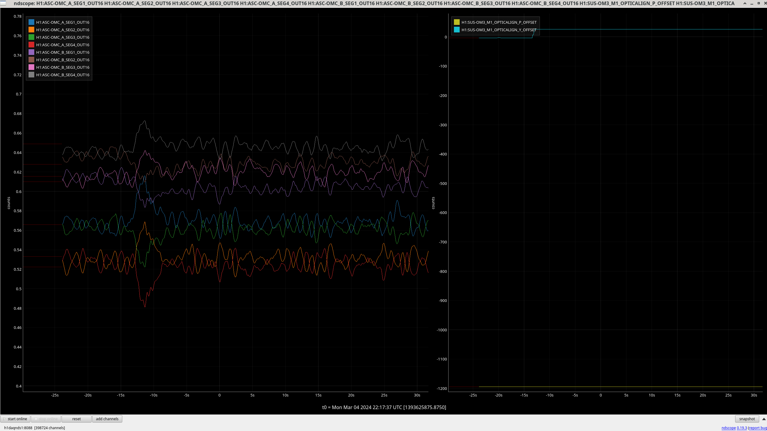
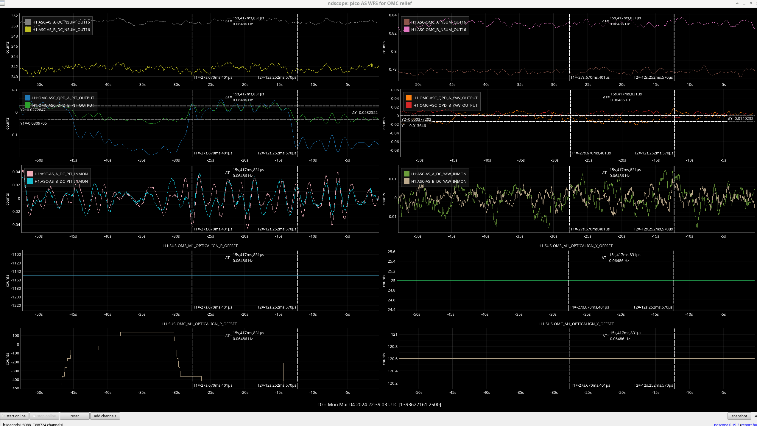
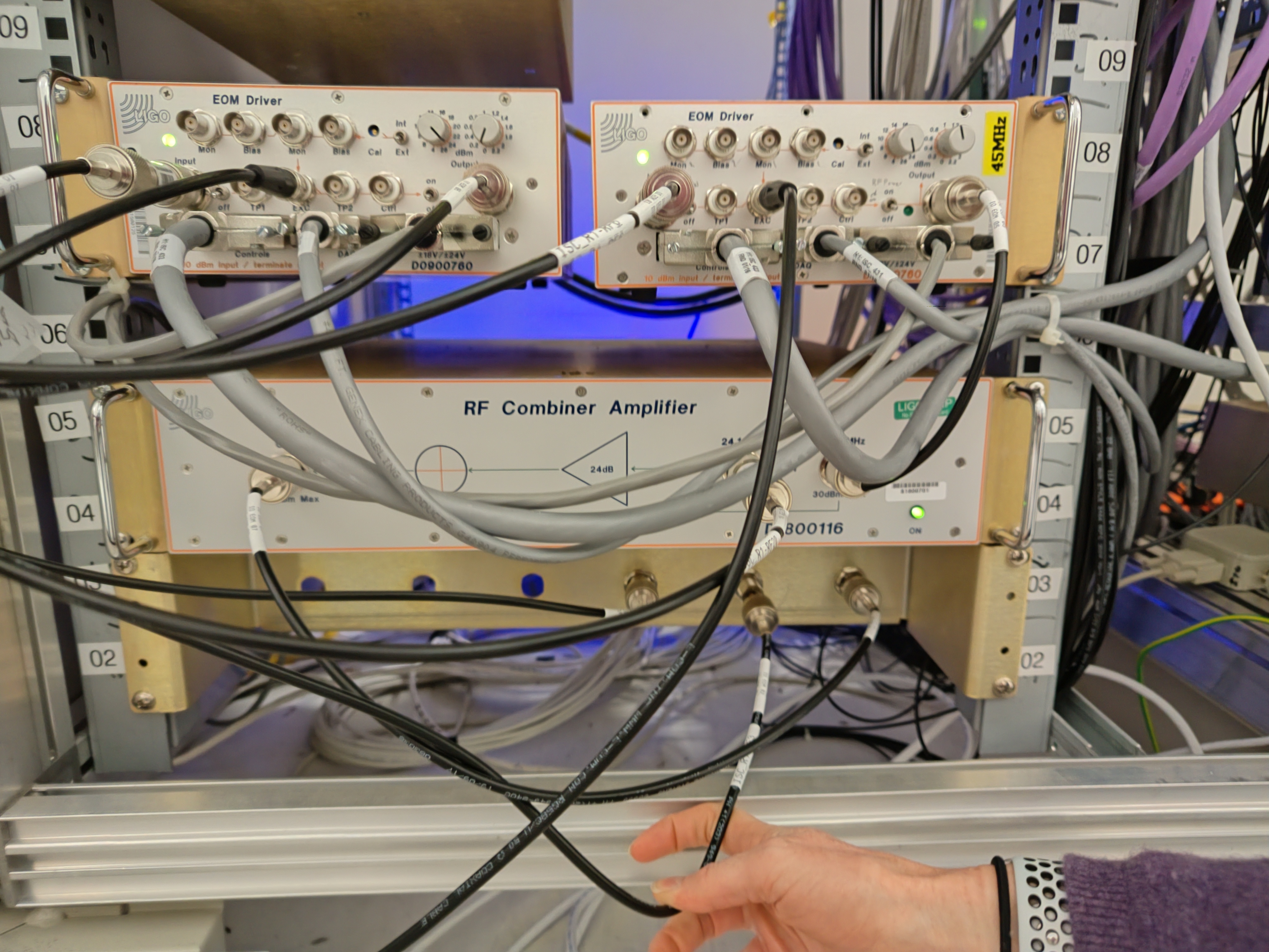
Image 2 shows the same thing when we increase the yaw signal on OM3 segment:
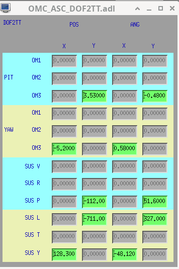
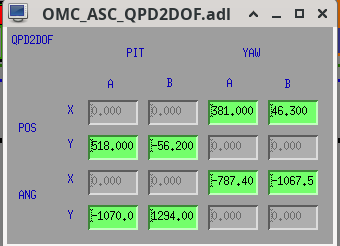
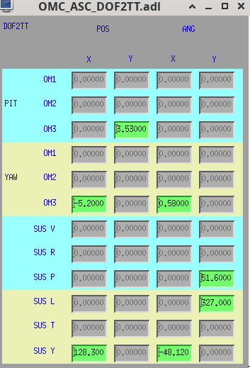
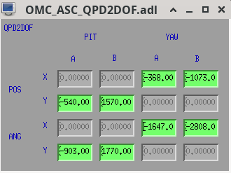
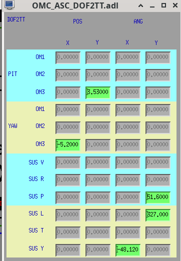
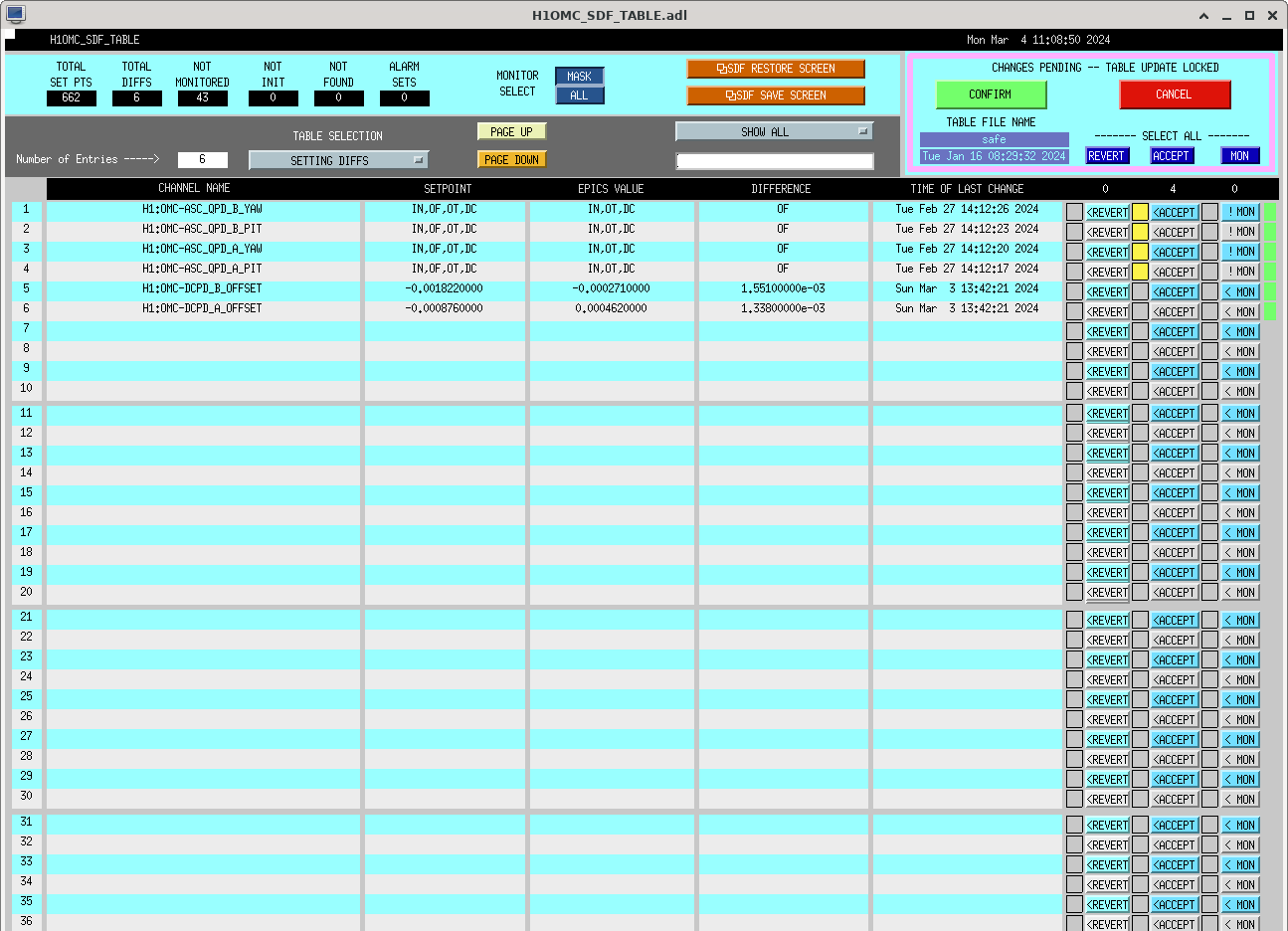
See image 3 and 4 for the original input and output matrices for the OMC ASC before our measurements started today.
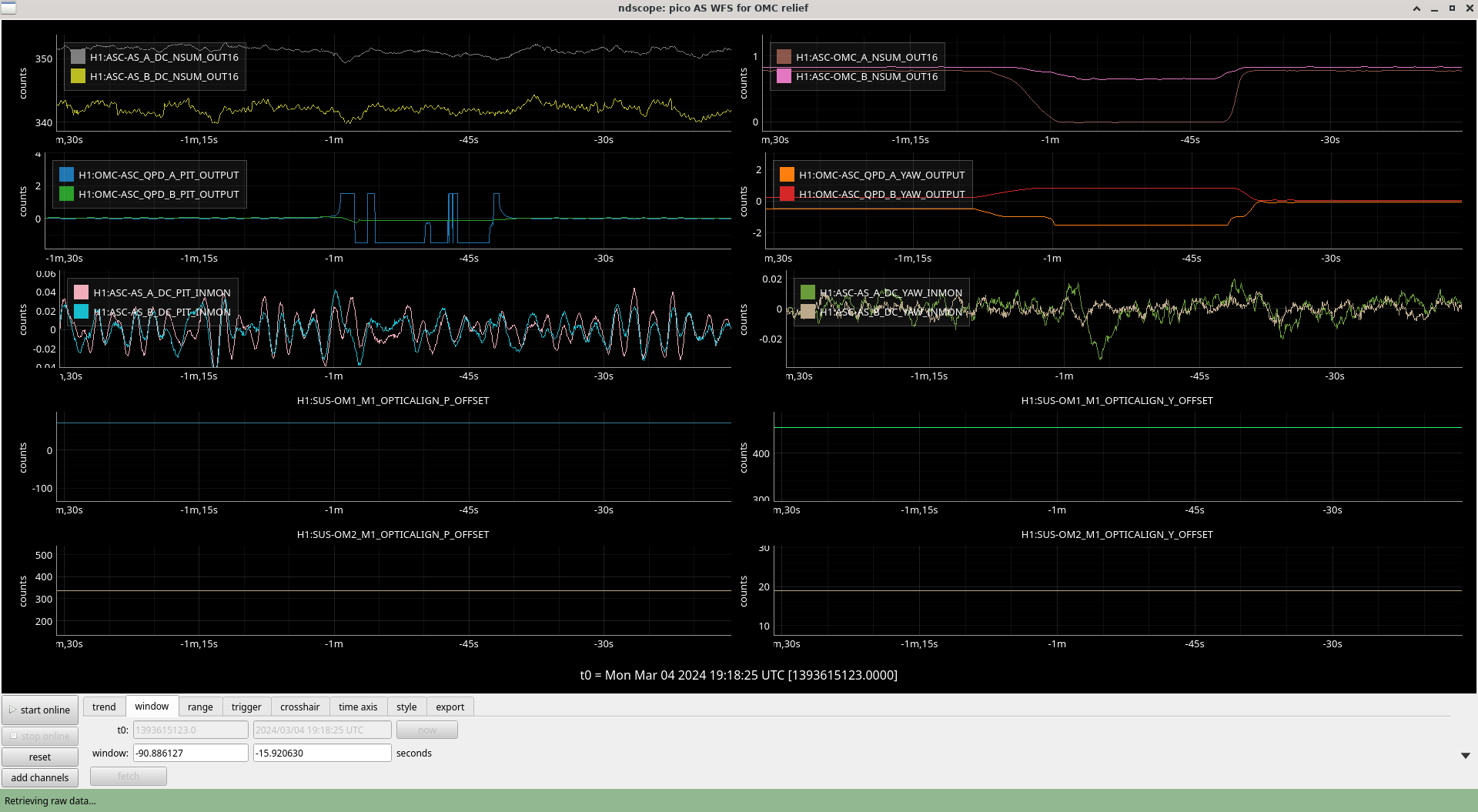
We measured the sensing matrix from pitch of OM3 to pitch and yaw of A and B by moving OM3 up in pitch by 50 counts. See image 5. You can see here that yaw on the QPDs is cross-coupled to pitch which we ignore for the purposes of this analysis but is good to note.
We measured the sensing matrix from pitch of OMC to pitch and yaw of A and B by moving OMC up in pitch by 500 counts (as it was hard to see a rerponse for 50). See image 6.
For both we divided the step on the QPD by 50, this might make the matrix coefficients differently scaled but we can fix this later by changing the loop bandwidths if neccessary.
This must be done with the ASC off so the step response can be seen.
Then we inverted this sensing matrix to get the input matrix after zeroing the output values for ANG Y and OM3 and POS Y and OMC sus.
We also have changed the output matrix in pitch to feedback only to feedback to OM3 for POS DOF and OMC only for ANG DOF to simplify the loops. See image 7.
Next we measure the yaw with steps of 50 counts again in the same way. Shown in image 8 and 9.
Then we changed output to decouple yaw drives as for pitch so pos drive only goes to OM3 and ANG drive only to OMC sus.
Then Craig and Matt had to re-measure the OMC in yaw as had measured the OMC offset drive wrongly.
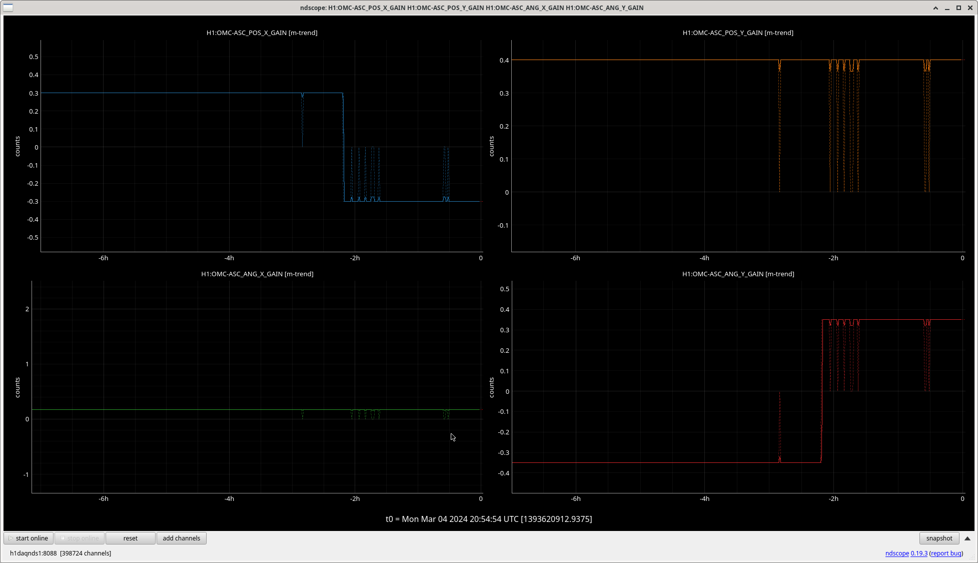
The new input matrix after inverting our sensing matrix for yaw and scaliing it by a factor of 50 is shown in image 10.
New output matrix (no value changes, just turned off POS feedback to OMC sus and ANG feedback to OM3) is shown in image 11.
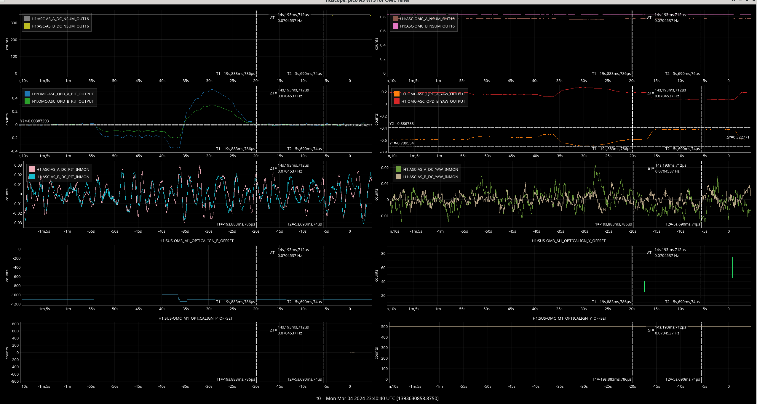
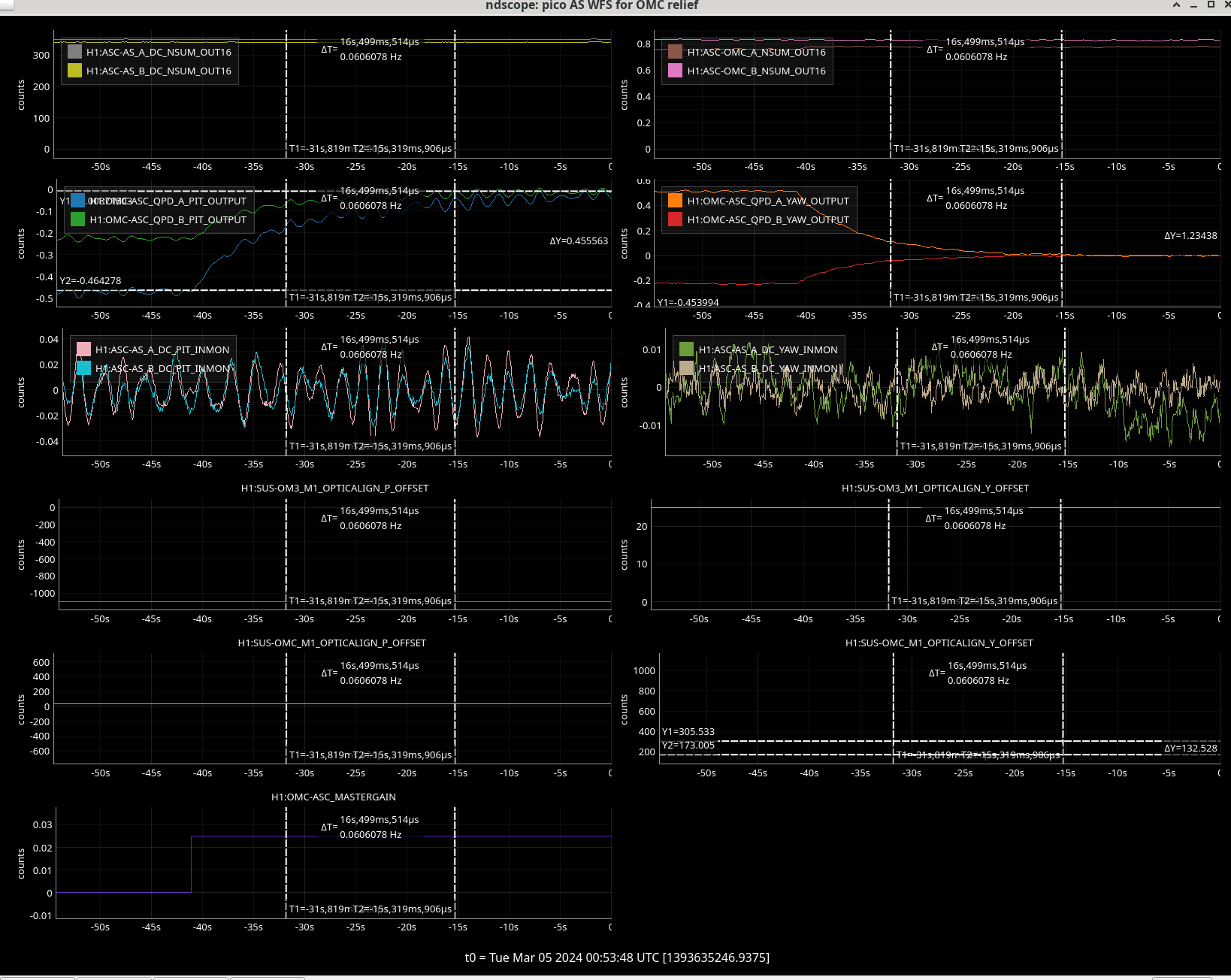
ASC now converges. Image 12 shows it working.
Matt locked the OMC with ASC on shown in image 13.
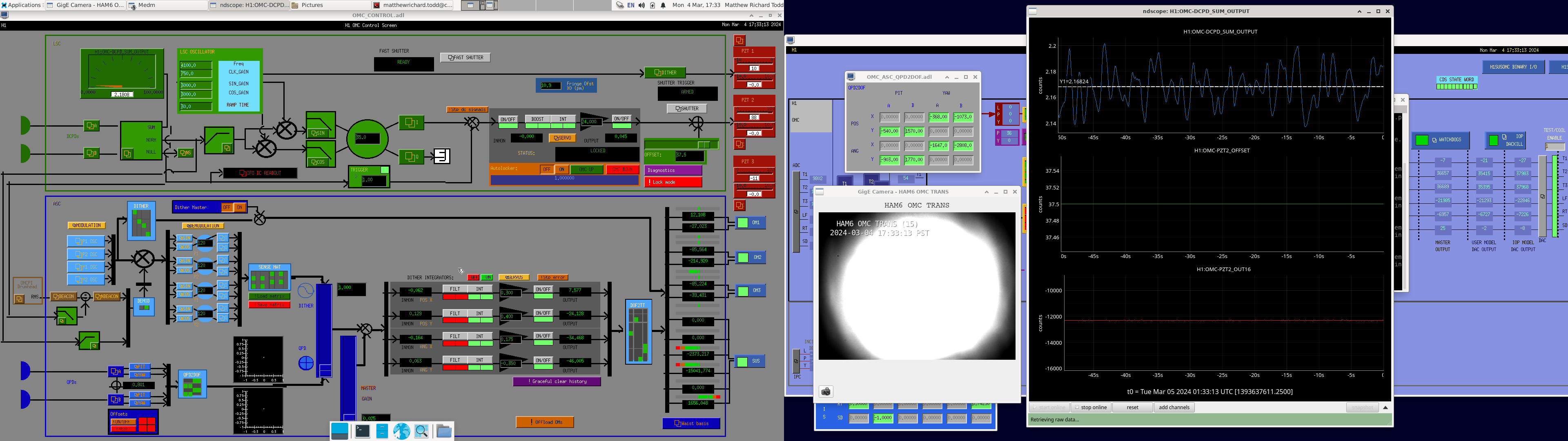
I've put in a "fake dark offset" OMC DCPD A to make the data from the OMC scans never be less than zero. This is still engaged at the moment.
The pressures: HAM7: ~2.3E-7 Torr HAM8: ~5.1E-7 Torr Corner: ~7.9E-8 Torr EX: ~1.9E-8 Torr Today's activities: - EX Turbo pump was valved out. The pressure rises, but will be consolidated at ~2.3E-8 - EX further schedule: it will be valved in to the beamtube at 3-5 - GV20 will be opened - Another corner RGA scan has been taken at the OMC beam: it shows, that now Hydrogen has the highest partial pressure, water is only at the 2nd place - The controller of IP1, IP2, and IP3, and IP14 (HAM6) was replaced with old style rebuilt controllers, which has higher maximum current, and therefore handles the pumps much better - they are not railing anymore but pumping nicely; but, they are now invisible in CDS - this needs attention very soon - Corner further schedule: as the pressure is coming down nicely (and the IPs are happy), if everything stays like this, at 3-5 the main GVs (GV5; GV7) can be opened - HAM8 RGA bakeout is ramped up, now it is baking for a few days - HAM7 RGA bakeout was done, and a scan was already taken. It shows that the RGA needs more bakeout, and also that the chamber is free from poisonous gases - So, the HAM7 IP was valved in, hence the huge pressure drop - Relay tube - HAM7 - HAM8 further schedule: This volume will be valved in to the main volume around Wednesday-Thursday - RV1; FCV1; FCV2; FCV3; FCV4; FCV8; FCV9 will be opened
HAM7 RGA scans posted to T2400018
RGA was baked for ~3 days at 175C prior to scans. Comparison to pre-vent scan attached, still RGA volume background limited for AMUs>45, but no appreciable difference compared to pre-vent scan
TITLE: 03/04 Day Shift: 16:00-00:00 UTC (08:00-16:00 PST), all times posted in UTC
STATE of H1: Planned Engineering
INCOMING OPERATOR: None
SHIFT SUMMARY: Main activities today involved OMC scans and background SQZ work as the arm gate valves will not open until tomorrow at the earliest.
LOG:
| Start Time | System | Name | Location | Lazer_Haz | Task | Time End |
|---|---|---|---|---|---|---|
| 23:29 | SAF | LASER SAFE | LVEA | - | The LVEA is LASER SAFE | 03:14 |
| 16:00 | FAC | Kim, Karen | FCES | - | Technical cleaning | 16:29 |
| 16:20 | VAC | Jordan | LVEA | - | HAM7 RGA | 16:24 |
| 16:42 | SQZ | Nutsinee | LVEA | - | CLF measurements at SQZ racks | 18:23 |
| 16:47 | SQZ | Fil | FCES | - | Reconnecting SQZT8 | 17:52 |
| 17:12 | SEI | Jim | Remote | - | Working on SEI HAM8 | 19:02 |
| 17:24 | FAC | Kim, Karen | LVEA | - | Technical cleaning | 18:18 |
| 17:31 | ISC | Camilla, Matt, Trent | EX | - | Turning on ALSX laser | 18:05 |
| 17:32 | SUS | Rahul | CR | - | HAM6 SUSs transfer functions | 18:23 |
| 17:43 | ISC | Sheila, Georgia, Jennie | LVEA | - | Turning off sidebands | 17:52 |
| 17:49 | CDS | Fernando | EX, EY | - | Oplev grounding work | 19:43 |
| 17:54 | CDS | Fil | EX | - | Checking ring heater power supply | 18:54 |
| 18:14 | VAC | Jordan | FCES | - | HAM8 RGA temp adjust | 18:43 |
| 18:14 | FAC | Karen | EY | - | Technical cleaning | 19:06 |
| 18:24 | SUS | Rahul | CR | - | HAM7 SUSs transfer functions | 19:20 |
| 18:35 | FAC | Chris | Outbuildings | - | Safety checks | 20:02 |
| 18:53 | FAC | Eric | LVEA | - | Checking doors | 19:29 |
| 20:10 | VAC | Janos | LVEA | - | Checking on pumps | 21:23 |
| 20:10 | VAC | Jordan | LVEA | - | HAM7 RGA | 20:18 |
| 21:28 | FAC | Randy | EY | - | Inventory | 22:40 |
| 21:30 | FAC | Chris | LVEA | - | Safety checks | 21:51 |
| 21:34 | VAC | Jordan | LVEA | - | Output tube (HAM4) RGA | 21:55 |
| 21:38 | SQZ | Nutsinee, Daniel | LVEA | - | SQZ racks | 22:40 |
| 21:39 | VAC | Travis | EX | - | Valve out turbopump, cleanup | 22:10 |
| 22:10 | VAC | Travis | MY | - | Dropping off equipment | 22:28 |
| 22:59 | VAC | Jordan | LVEA | - | HAM7 RGA | 23:43 |
| 23:12 | SQZ | Camilla, Julian, Trent, Georgia | Optics Lab | LOCAL | SHG work | Ongoing |
| 23:40 | PCAL | Tony, Francisco | PCal Lab | LOCAL | PCal measurements | 23:48 |
| 23:52 | VAC | Jordan. Gerardo | LVEA | - | Opening HAM7 ion pump | Ongoing |
Jennie W, Sheila, Elenna, Georgia, Ryan S.
Even though Georgia and Trever successfully had the OMC ASC working yesterday before they took OMC scans we have again had problems with the ASC today. We don't fully understand why this is as we had tweaked the alignment on Friday in order to ensure the OMC ASC converged without saturating any suspensions.
We turned on the OMC guardian and it complained about no light on the OMC DCPDs.
We turned on DC centering and SR2 loop and then tried to turn on OMC ASC but it saturated the OMC suspension - this may have been because OMC QPD A was completely off the PD. After we turned off the ASC the beamns were centred again on QPD A and B for the OMC but turning on the ASC still staurates OMC suspension.
Tried turning this on again with SR2 loop off and this still happens.
Same with DC centering loops off.
See first attached image of the ASC loops running away.
In the commissioning meeting it was pointed out that the GRD OMC node might have flipped the POS X and ANG Y gains back to the nominal sign which we had changed last week to make the ASC converge.
Elenna and Matt trended the gains and found that this does indeed happen and flipped them back. After discussions with Ryan we note these gains are hard coded into the guardian so we may need to change this is in the code before the run starts but for OMC scans we will just set these manually and also not accept them in SDF yet.
Sheila accepted the change to the QPD pitch and yaw offsets we made last week. That is we switched them off. See second image.
Matthew Todd, Elenna Capote Elenna trended the pos and ang gains of the OMC_ASC back in time, and noticed a few hours ago that the signs of pos-x and ang-y were flipped, which we think corresponds to a time when the OMC Guardian was engaged. We corrected the gain signs in pos-x and ang-y (+, and -,) respectively. We are choosing not to SDF this change at this time.
EX Ring Heater Chassis is now powered on.
We turned off the 9, 45 and 118 MHz sidebands at the rack beside the PSL enclosure.
This was to hopefully do OMC scans with no sidebands on at some time this week.
Attached are photos featuring Sheila and Georgia showing where to turn off the 9 and 45 MHz in the electronics rack on the opposite side of the PSL enclosure from the main entrance door.
You have to turn off these two amplifiers.
The second photo shows where to unplug the cable for the 118 MHz at the bottom of the rack.
Sheila, Trent, and Matt We turned the 9, 45, and 118MHz sidebands back on, and plan to rescan the OMC with these on.
WP 11742
Field cabling to SQZT8 is reconnected.
Mon Mar 04 10:09:19 2024 INFO: Fill completed in 9min 15secs
Travis confirmed a good fill curbside.
FAMIS 20018
PSL incursion last Tuesday (alog76002) explains several abnormal trends happening on that day, including the rarely-done increase in pump diode currents in AMP2.
For FAMIS #26287: All looks mostly for the last week for all site HVAC fans (see attached trends).
TITLE: 03/04 Day Shift: 16:00-00:00 UTC (08:00-16:00 PST), all times posted in UTC
STATE of H1: Planned Engineering
OUTGOING OPERATOR: None
CURRENT ENVIRONMENT:
SEI_ENV state: EARTHQUAKE
Wind: 15mph Gusts, 14mph 5min avg
Primary useism: 0.02 μm/s
Secondary useism: 0.20 μm/s
QUICK SUMMARY:
SEI_ENV error has been fixed; issue was a typo where SEI_CONF was requested to go to the "EARTHQUAKE" instead of "EARTH_QUAKE", which is the correct (and silly) state name.
The air handling units at the corner station have been operating with many functions in a manual setting. This has taken automatic control away from the DDC system and made for inefficiencies throughout the system. After discussing with Richard, we have given automatic control back to the supply air temperature set point function as well as to the dampers to see what effect this has in terms of efficiency and temperature control of the LVEA. Because the dampers will now modulate more frequently, this will cause fluctuations in the vibrometers that will be evident in the trends. These changes in control will be evaluated over the next couple days to determine effectiveness.
Trent, Georgia, and Craig We came in to take OMC scans to determine the finesse. We wanted to take scans with the 9 and 45 MHz sidebands on and off. Setup: - Took the IMC offline and ran the dark offset scripts [/opt/rtcds/userapps/release/isc/h1/scripts/dark_offsets/dark_offsets_exe.py] - Turned on DC3 and DC4 by turning on the inputs (left on during measurements) - Turned on the OMC ASC by changing the master gain from 0 to 0.025 (left on during measurements) - Turned off the offset on OMC PZT2 - Ran an OMC scan [/ligo/home/trent.gayer/OMC_scans/2023_03_03_single_bounce_omc_scan.xml] Analysis: - Analyzed the scan with the following command [python3 /ligo/gitcommon/labutils/omc_scan/OMCscan.py 1393538828 95 "2W single bounce side bands nominal (45 @ 27.0dB, 9 @ 23.4dB)" "single bounce" --verbose --make_plots]. The data looks strange on the log scale because the signal goes negative. This script generated the first attached plot. - Added a dodgey little offset (0.001) to OMC-dcpd_sum to fix the negative numbers - We changed the duration time from 95 to 80 so that we only included 2 carrier peaks instead of 3. This helped with the peak identification which can be seen in the second attached plot. We also changed the gps time seen in the following command [python3 OMCscan.py 1393542033 80 "2W single bounce side bands nominal (45 @ 27.0dB, 9 @ 23.4dB)" "single bounce" --verbose --make_plots] What's the finesse: - To calculate the finesse we ran the file [/ligo/gitcommon/labutils/omc_scan/fit_peak.py]. We had to change variables gps_start, duration, description, mode, and num_fsr since those were hard-coded in. - We got the third attached plot from this code. - This plot gives two HWHM's, one from the data at 0.341 MHz and one from the lorentzian fit at 0.327 MHz. This gives two finesses: 388 using the data, 405 using the fit. We think that the fit is more trustworthy than the data because it uses more of the linewidth. - The variance given by curve_fit within the code is 1.16E-08. Take the square root to get the standard deviation. We estimated the error to be 0.04 No Sidebands: - We tried to find the button that turns off the 9 and 45 MHz sidebands were unsuccessful. In the meantime, we decided to just change the RF set for both sidebands to 4dBm. This is the lowest the sliders could go. - The fourth attached plot shows the signal with and without the sidebands
Sun Mar 03 10:08:56 2024 INFO: Fill completed in 8min 52secs
Now we are transitioning from winter to spring and the TC-mins have been well below -100C, I've lowered the trip temp from -60C to -90C, this is shown in the Y-cursor on the plot.
Following up the recent measurement (alog75927) the dip in the middle of the SHG sinc function seems real. SHG was locked when the data was saved and the dip in the ndscope wasn't a result of data averaging. I'm taking another set of measurements with more data points to confirm. The measurement will take about 5 hours. The start time was ~00:20.
This log goes into more detail from yesterday's work (alog75754) and what Jason and I did today.
After we checked the chiller lines had no leaks without the table in loop, we added the tables in next. The Y table was free of leaks, but the X table had a slow drip from a few od the push to connect fittings on the RF driver (attachment 1). We swapped all of these fittings for new ones and cut the 1/4" diameter tubes ~0.5", with a cutter that we borrowed from PSL, for fresh connections. This worked great and there were no more leaks.
To fire up the laser to wanted to avoid the fried opamps that we've had in the past, so we turned on the CO2X electronics in this order:
No fried opamps this way. When we turned the newly refurbished laser on, it output 53W according to our Thorlabs S322C power head placed just after M1. The alignment was far off in yaw, not even hitting POL1. Jason and I first yawed the laser itself within its mounting bolt holes, which didn't move much, then started to align downstream. We eventually got the beam to the irises before the periscope, but had moved a large majority of the optics along the way - M1, ISSPO, PM1, PM2, M4, M5, M6 (table drawing). Using the FLIR One camera we got the beam to hit the irises in a similar way to before the laser swap (before, iris1 now, iris2 now). We then checked on the table FLIR for mask alignment. Here we noticed that the annular mask was a little off horizontally, so we translated the mask to better match the previous position (before, annular now). Once we inject into vacuum we might need to make some more minor changes on table, but this looks good for now.
The last steps today were to recalibrate the thermopile at the laser head and verify that the power meter is still centered on the beam. The power meter need a small translation to center the beam. The gain in the laser head WATTS filter was previously 8.58755 and we eventually ended up at 13.904. Jason used new_gain=old_gain*Pm /PE , where Pm is power measured with the Thorlabs S322C just after M1 and PE is the power reported in Epics with the old calibration. We iterated this a few times to make sure it was as close as we could feasibly get.
Next steps are to inject the beam into vacuum and check centering with the HWS. The plan is for this to be done just before commissioning starts in a few weeks.
We left the CO2X laser keyed off and ready for the upcoming laser safe work.
Pico alignment onto ITMX done in 75987. Rotation Stage recalibrated in 76008.
The new laser is reporting an incorrect temperature via H1:TCS-ITMX_CO2_LASERTEMPERATURE, plot attached. There is a RTD temperature sensor on top of the laser but there's no reason it should have change.
It could be related to an EDC change /DAC restart 23rd Jan 75522 as IY is also reporting a lower (but still believable) temperature.
H1:TCS-ITMX_CO2_LASERTEMPERATURE is a SLOW channel, is a DAQ(SLOW) model = H1EDC rate = 16 type = FLOAT