[Jennie, Evan, Gabriele]
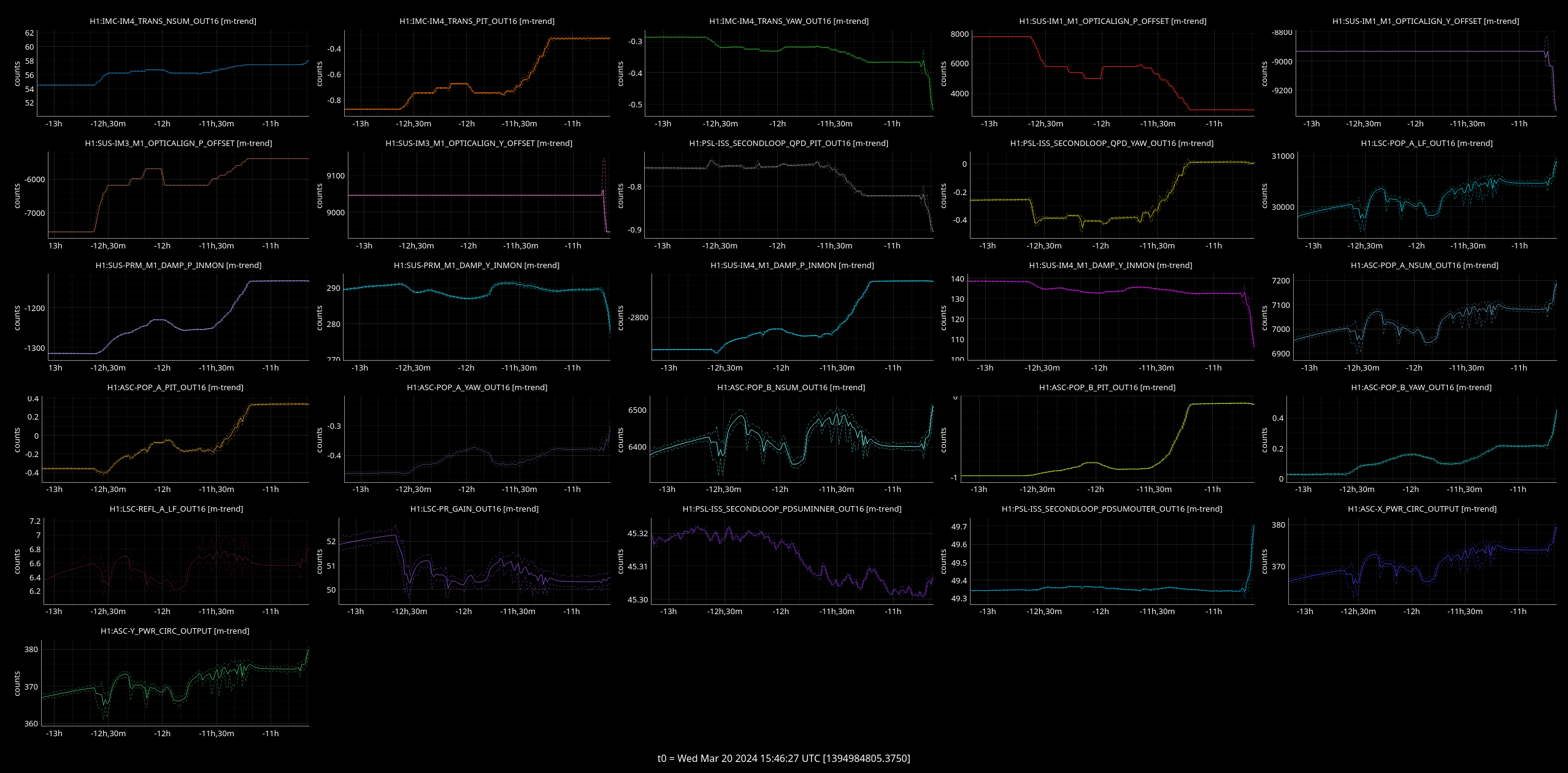
We tried again to move the input beam pointing in-lock, similarly to what was done in 76359.
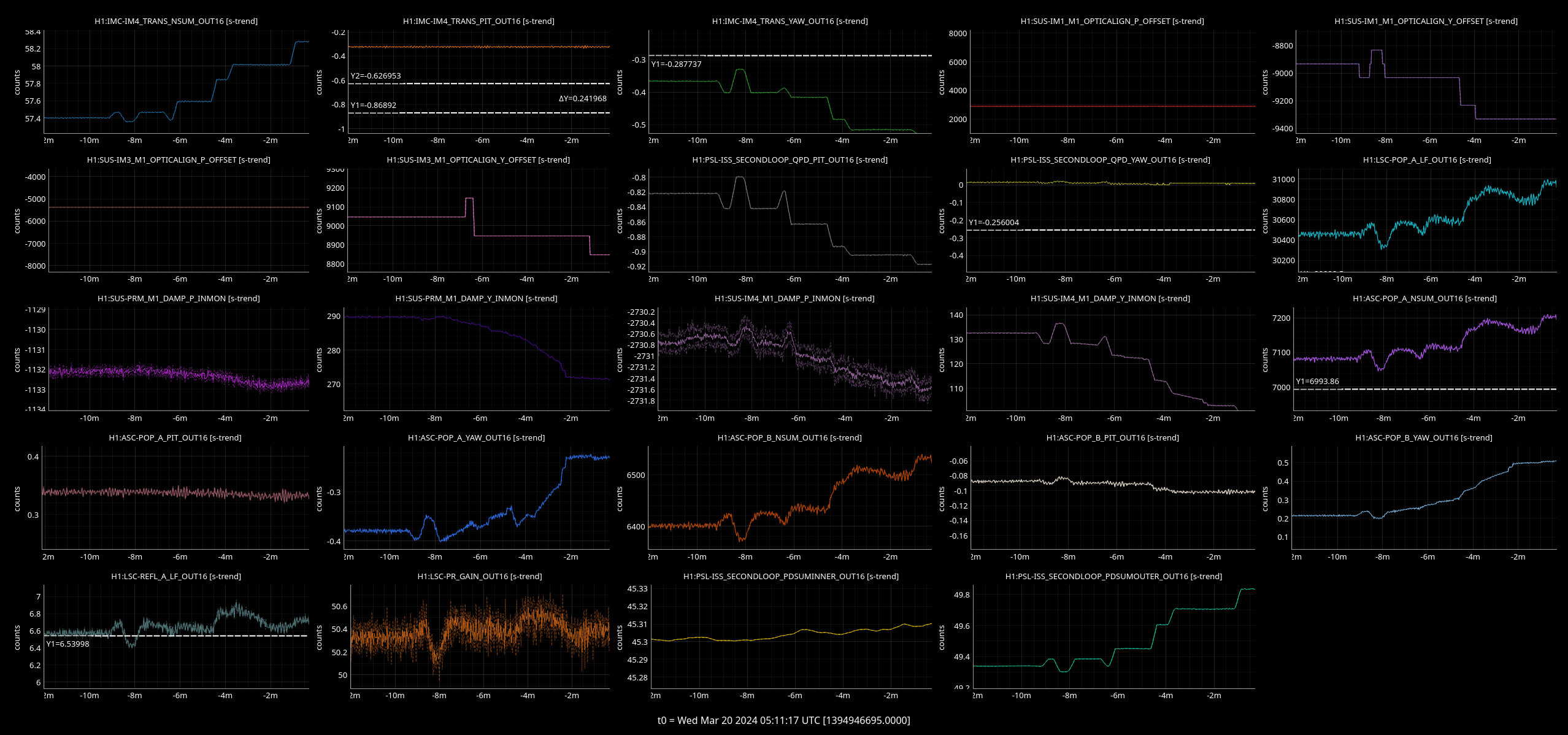
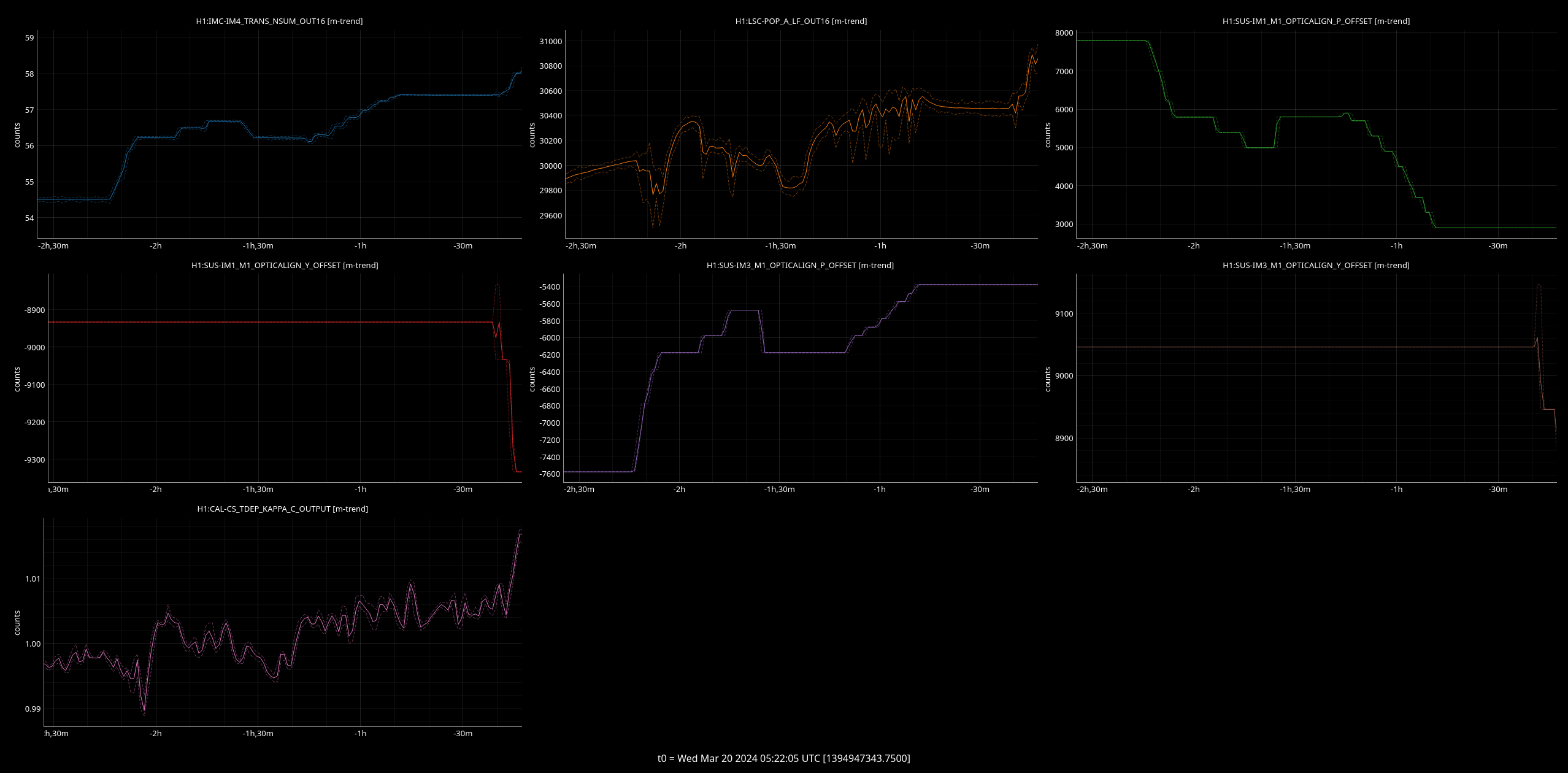
First we moved IM1 and IM3 in pitch, looking at IM4_TRANS and POP_LF. We could increase the power in IM4, and we moved until we reached a maximum in POP_LF. Half way during the test we switched back to ADS from cameras, but it turns out that the PRM ADS was moving in the wrong direction. We went back to camera servos (restoring the original, correct offsets) and helped PRM along to speed up the camera servo convergence.
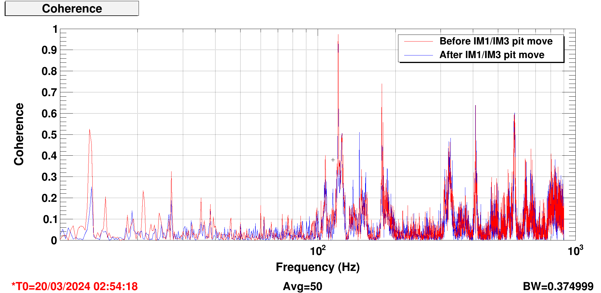
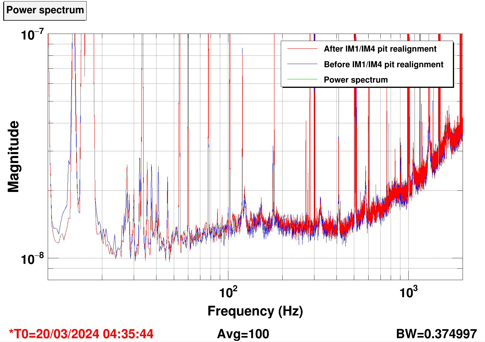
When we reached this maximum of POP_LF by moving pitch IM1 and IM3, we checked DARM: there was more noise in DARM at low frequency and around 100 Hz, the range was lower, but coherence with jitter was unchanged. Evan tried to improve things by tuning the SQZ, without luck.
We then moved to yaw, and we could improve IM4 and POP_LF further. Unfortunately we lost lock during the test. We don't believe we caused the lock loss.
The change in input beam alignment had a good effect on the optical gain, KAPPA_C increased by 2% (yaw being the most effective direction). For comparison IM4_TRANS improved by 6.6%, POP_LF improved by 2.8%
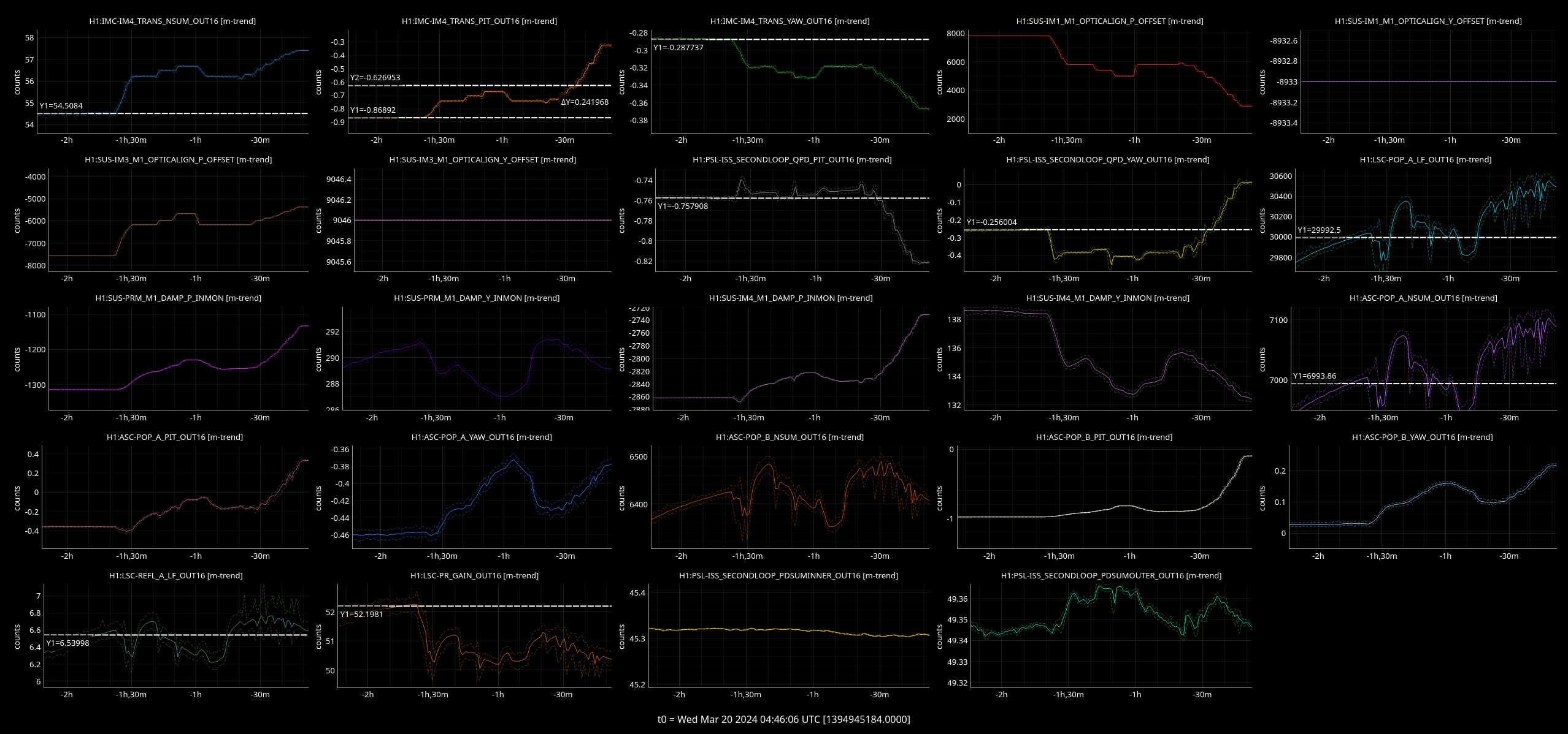
The arm power also increased proportionally to LSC-POP and ASC-POP. I think this means that moving the input pointing we were fixing some clipping in the PRC. It's worth repeating the test: we could go back to the pitch position we found (by moving IM1, IM3 with a long ramp, and also moving PRM to the new value, and maybe also IM4?). From there we can restart the yaw motion, which seemed promising.
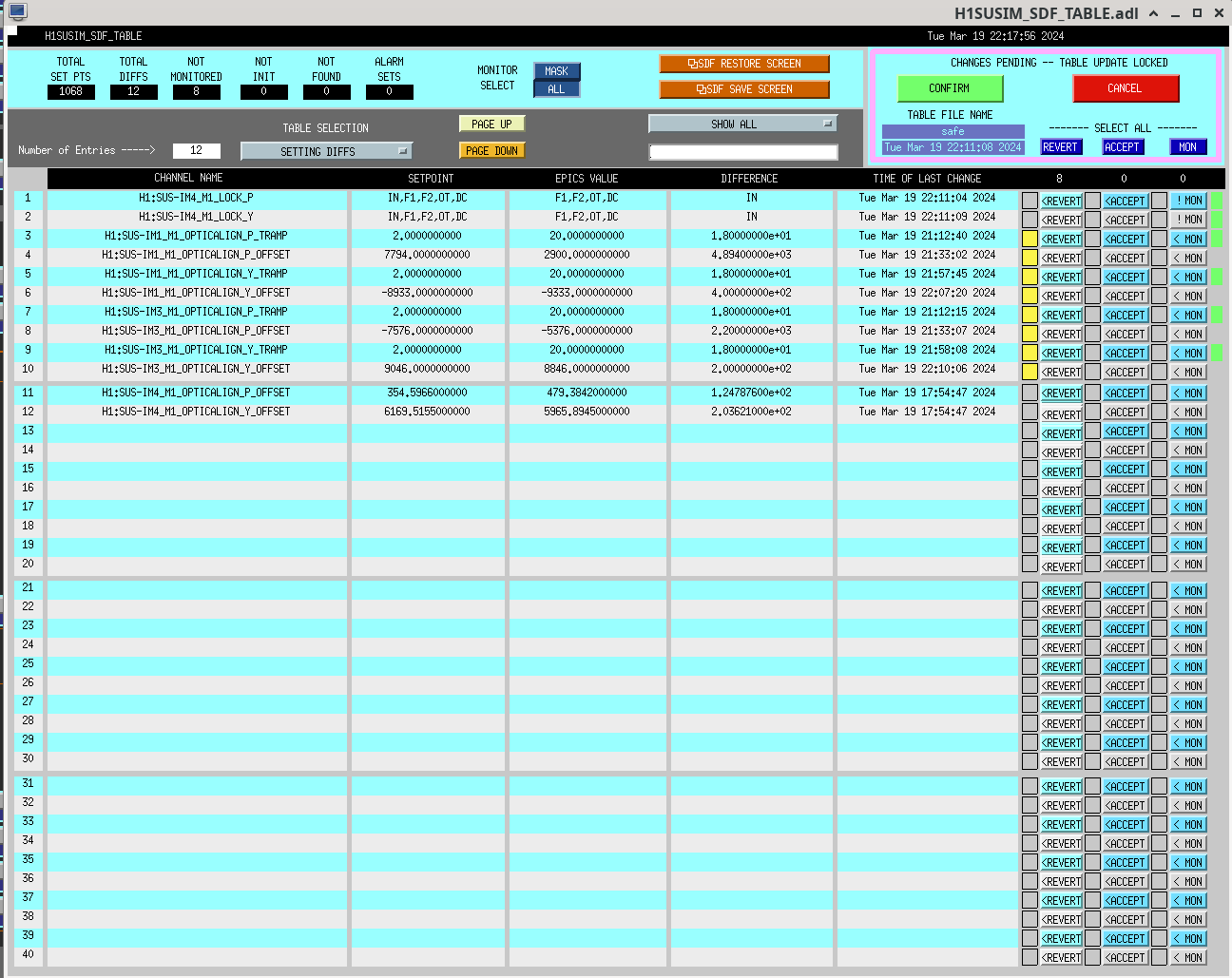
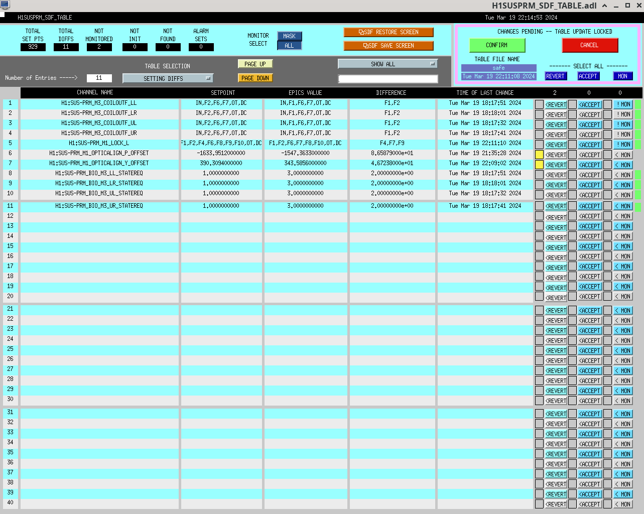
I reverted the alignment changes to IM1, IM3 and PRM. See attched images of the SDFs for SUSPRM and SUSIM models.
For future reference, here are the moves we did (in SUS offset sliders) or loops did for us (in M1 DAMP IN units, should be the same as sliders)
| Optic (pitch) | Initial value | Final value | Change |
| IM1 (us moving) | 7794 | 2900 | -4894 |
| IM3 (us moving) | -7576 | -5376 | +2200 |
| IM4 (loop) | -2862 | -2731 | +131 |
| PRM (loop helped by us) | -1314 | -1132 | +182 |
| PR2 (loop) | -484 | -516 | -32 |
| PR3 | none | ||
| BS | none |
EvanH, LouisD, GabrieleV, FranciscoL
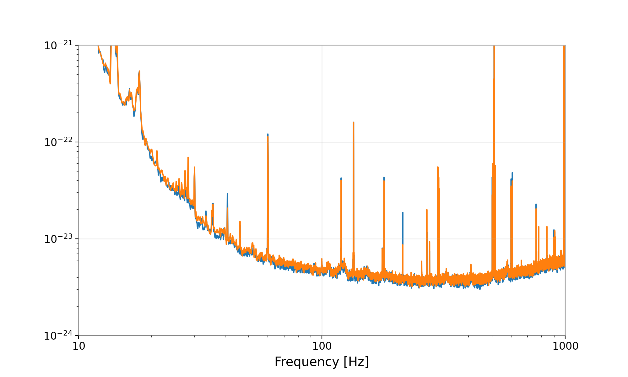
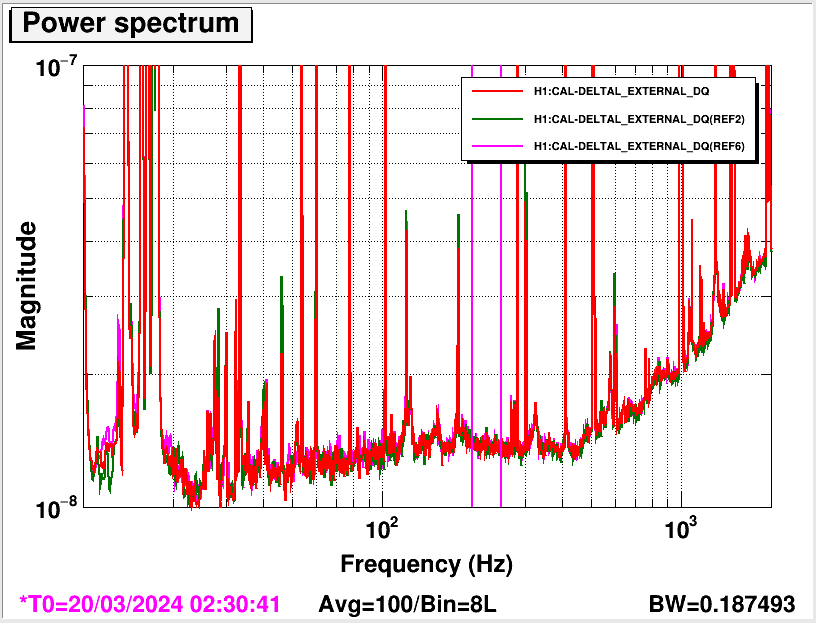
We wanted to see if frequency noise was the source of noise in DARM. To test that, we measured the DARM power spectrum from REFL A and REFL B with various configurations, namely we measured both A and B in loop, then only A in loop and only B in loop.
If the source of noise was frequency noise, we should see a increase of sqrt(2) when measuring from only one photodiode.
We do not see any increase in the DARM power spectrum (see attached figure) so the contribution from frequency noise is not the culprit for the excess noise.
Jennie W, Sheila
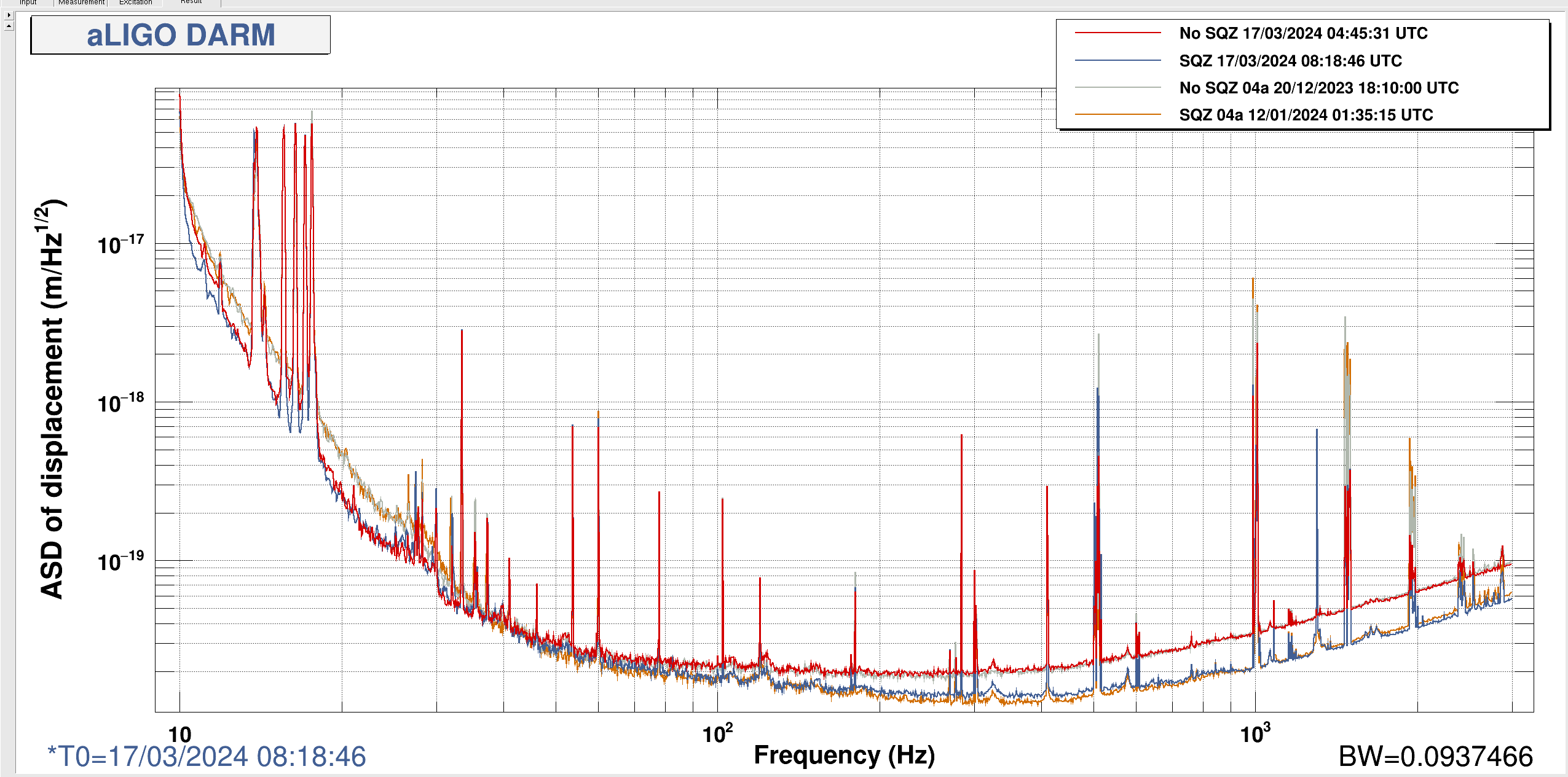
Time for No Squeezing in 04a: 20/12/2023 18:10:00 UTC
Time for Squeezing in 04a: 12/01/2024 01:35:15 UTC
Time for No squeezing pre ER16: 17/03/2024 04:45:31 UTC
Time for Squeezing pre ER16: 17/03/2024 08:18:46 UTC
I used the calibration from 15th March for the pre-ER16 data - 20240315T01223Z
and the calibration from 27th October 2023 for the 04a data - 20231027T203619Z
Integrating the area under the curve using the cursors in DTT, the RMS motion in 200Hz to 230 Hz for the pre-ER16 data is roughly 4% higher than for the 04a data.
I am going to try plotting the excess noise in the no sqz data now vs. that in 04a to get more of an idea if this excess noise is consistent with technical noise and can explain the discrepancy in the SQZ noise now and in 04a.
For info here is the correlated noise budget from 13th March that Craig did.
TITLE: 03/19 Eve Shift: 23:00-07:00 UTC (16:00-00:00 PST), all times posted in UTC
STATE of H1: Commissioning
OUTGOING OPERATOR: Corey
CURRENT ENVIRONMENT:
SEI_ENV state: CALM
Wind: 16mph Gusts, 14mph 5min avg
Primary useism: 0.03 μm/s
Secondary useism: 0.19 μm/s
QUICK SUMMARY:
TITLE: 03/19 Day Shift: 15:00-23:00 UTC (08:00-16:00 PST), all times posted in UTC
STATE of H1: Commissioning
INCOMING OPERATOR: Corey
SHIFT SUMMARY: Tuesday Maintenance day, we are now back in NOMINAL_LOW_NOISE
LOG:
15:00 Tuesday maintenance start
19:26 Relocking start, doing an initial alignment
- Had to trend Driftmon values for the ITMs and BS and move them back to around where they were a few hours ago, since we had updated the SUS and ISI models for the ITMs and the BS and had things trip.
20:58 Lockloss from PRMI_ASC
- Was having trouble getting DRMI and PRMI, even though we had run an initial alignment
21:12 Lockloss from PRMI_ASC
- Still having trouble with getting the PRMI alignment
21:25 Lockloss from ACQUIRE_PRMI
21:42 Lockloss from DHARD_WFS
- EX saturation right at LL
22:21 NOMINAL_LOW_NOISE
- From LOCKING_ARMS_GREEN to NOMINAL_LOW_NOISE: 39mins
| Start Time | System | Name | Location | Lazer_Haz | Task | Time End |
|---|---|---|---|---|---|---|
| 15:01 | IAS | Tyler | LVEA | n | Prepping FARO for measurements | 15:17 |
| 15:07 | PCAL | Tony, Dripta | EY | YES | PCAL measurements | 18:03 |
| 15:07 | FAC | Karen | EY | YES | Tech clean | 15:58 |
| 15:07 | FAC | Kim | EX | n | Tech clean | 16:05 |
| 15:28 | PCAL | Rick, Francisco, Daiki | EX | n | Centering PCAL beams | 17:49 |
| 15:40 | SUS/ISI | Oli/Dave | CR | n | New ITM and BS models | 18:49 |
| 15:40 | DAQ | Dave | remote | n | Restart DAQ for SUS/ISI changes | 18:59 |
| 15:45 | VAC | Janos, Jordan, Gerardo, Travis | LVEA - Beer Garden | n | Purge line work | 18:48 |
| 15:47 | OpLev | Jason, Fernando | LVEA | n | Oplev cabling | 17:10 |
| 15:52 | EE | Fil | CER | n | Swapping chassis | 16:12 |
| 15:59 | FAC | Karen | FCES | n | Tech clean | 16:50 |
| 16:06 | FAC | Kim | HAM Shack | n | Tech clean | 17:22 |
| 16:07 | IAS | Tyler, RyanC, Jason | LVEA | n | FARO work | 18:45 |
| 16:09 | HWS | TJ, Camilla, Gabriele | EX | n | HWS work | 18:30 |
| 16:32 | CDS | Jonathan | LVEA | n | Meeting up with Fernando and Jason | 16:38 |
| 17:01 | tour | Keita, Minhyo, Artem | LVEA | n | tour | 18:25 |
| 17:12 | ISI | Jim | LVEA - HAM7 | n | Adding resistor to HAM7 ISI | 18:33 |
| 17:13 | Mitchell | LVEA | n | Storage crates | 18:43 | |
| 17:15 | HWS | Camilla | Optics Lab | n | Getting beam profiler | 17:19 |
| 17:23 | FAC | Kim | LVEA | n | Tech clean | 18:51 |
| 18:02 | tour | Rick, Daiki | LVEA | n | tour | 18:32 |
| 18:04 | PCAL | Tony, Dripta | Optics Lab | y (local) | pcal stuff | 18:49 |
| 18:26 | FAC | Ken | EX, EY, MX, MY | n | Replacing lights | 21:29 |
| 18:30 | VAC | Jordan | EX | n | grabbing parts | 18:49 |
| 18:30 | PCAL | Tony, Fil | EY | n | Checking temps | 19:00 |
| 18:38 | TCS | TJ, Camilla | LVEA | n | TCS supports | 19:18 |
| 18:53 | Fernando | LVEA | n | ? :( | 19:20 | |
| 18:53 | Keita, Minhyo | CR | n | Single bounce measurements | 19:23 | |
| 19:31 | WLK | Ibrahim | YARM | n | A nice leisurely stroll to absorb warmth | 20:25 |
| 19:49 | PCAL | Tony | PCAL Lab | y(local) | PCALing | 21:36 |
| 19:53 | CDS | Fil | FCES | n | Inventory | 20:53 |
| 20:31 | SQZ | Nutsinee | LVEA SQZ table | y(local) | Very fast measurement | 20:48 |
| 20:36 | SHG | Julian, Camilla | Optics Lab | y(local) | SHG work | 23:05 |
| 22:35 | Rahul | CER | n | Getting stuff | 22:40 |
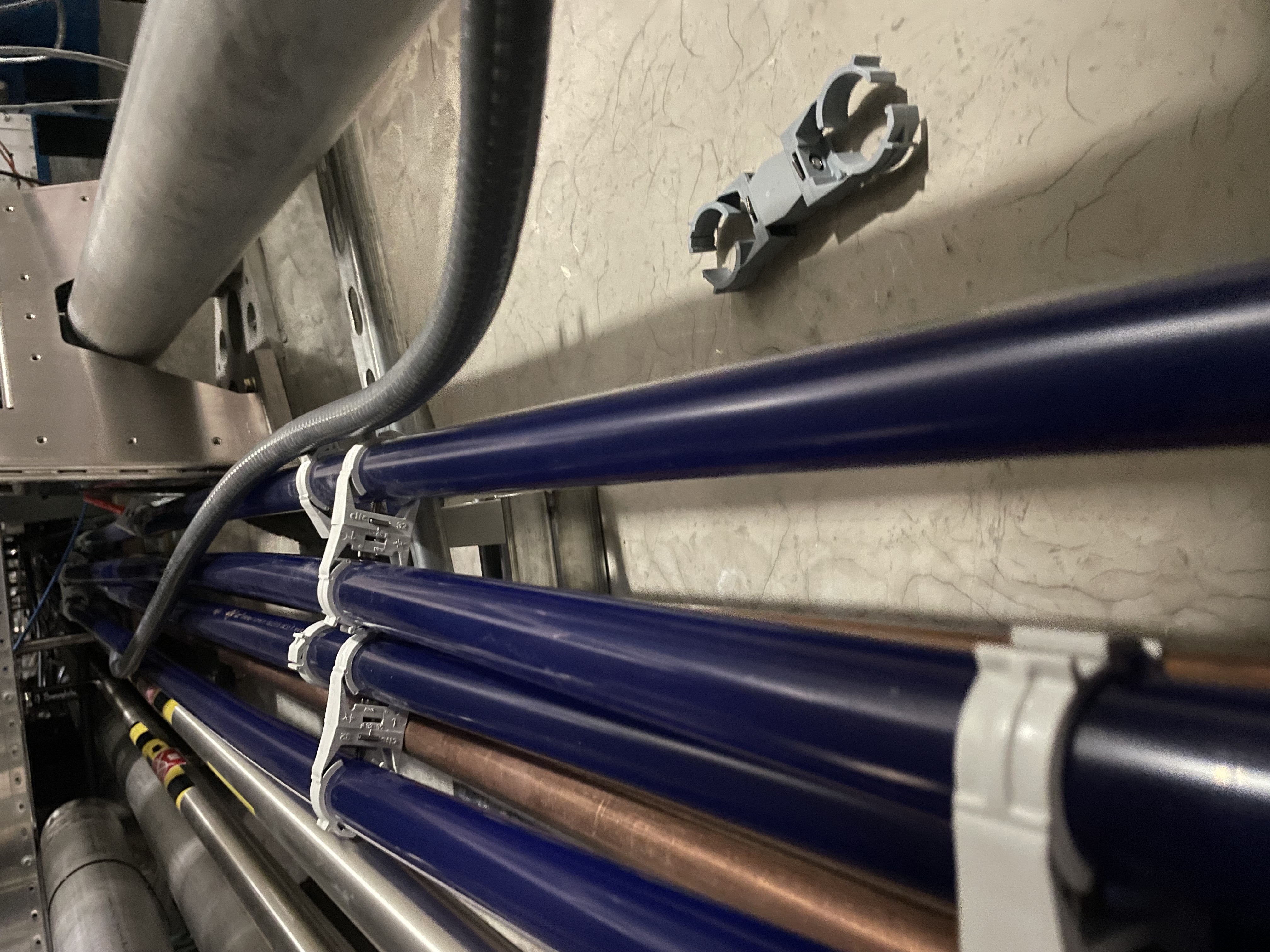
Today Camilla and I added a few diagonal pipe supports to the TCS chiller lines under the output tube in the LVEA. These four lines were designed to be in a 2x2 stack, but tend to fall over flat due to only using horizontal and veritcal supports (first attachment). We added four in total so far, but still need to add some to the top of the cable/pipe bridge and maybe in the mechanical room. I didn't get any final pictures, but I'll get some when we finish the rest.
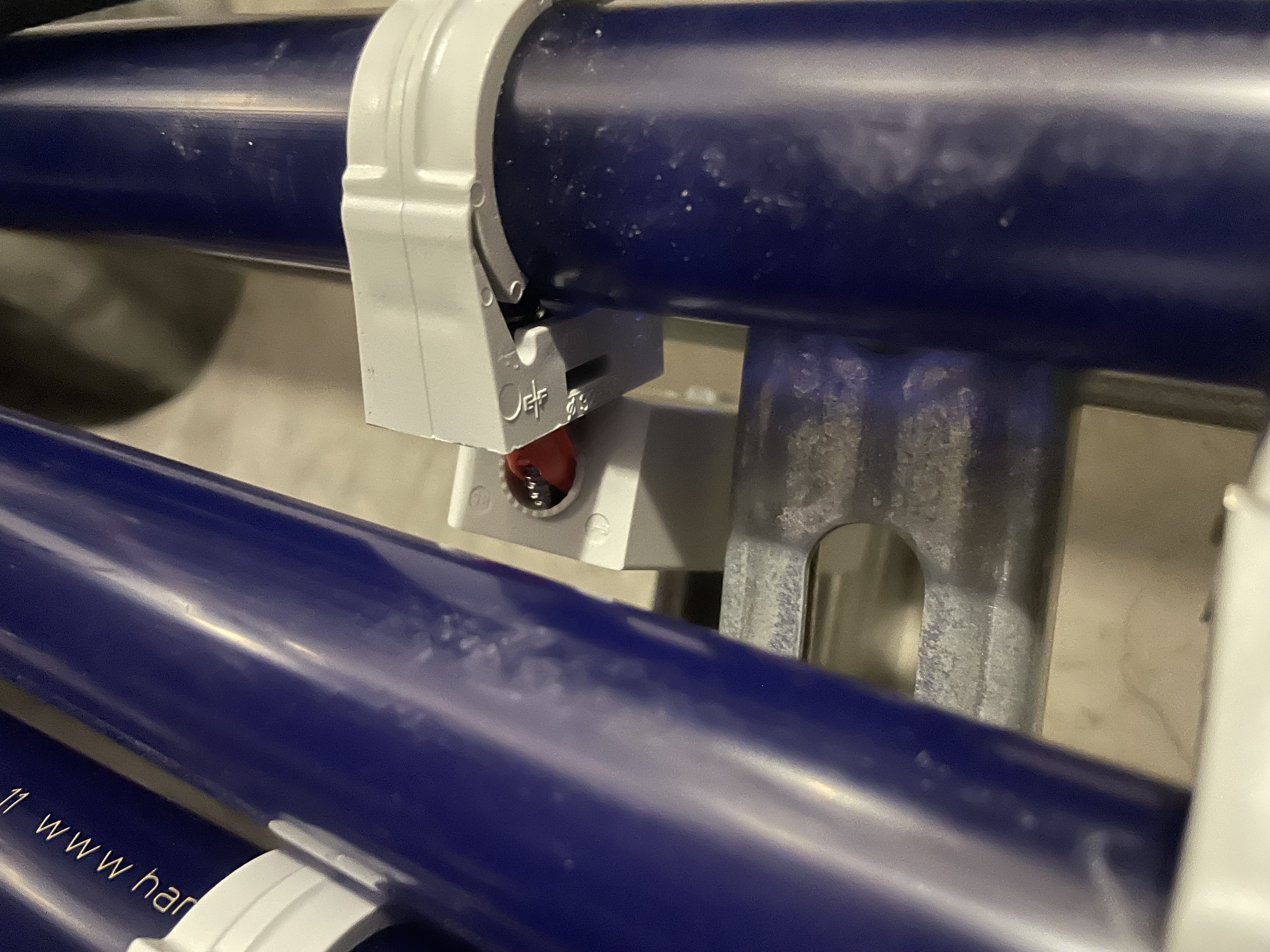
There was one place that we found that the pipe clamp had been pulled out of its base (second attachment). This seemed to be using a drywall anchor in the base rather than the designed hardware. Since we don't have the hardware on hand and due to access couldn't easily get to it, we pushed the anchor back in and placed the diagonal support next to it. This should help hold it in, but we'll keep an eye on it.
The document has been uploaded to the dcc.
A PCAL End station measurement was performed at End Y today. Analysis Pending.
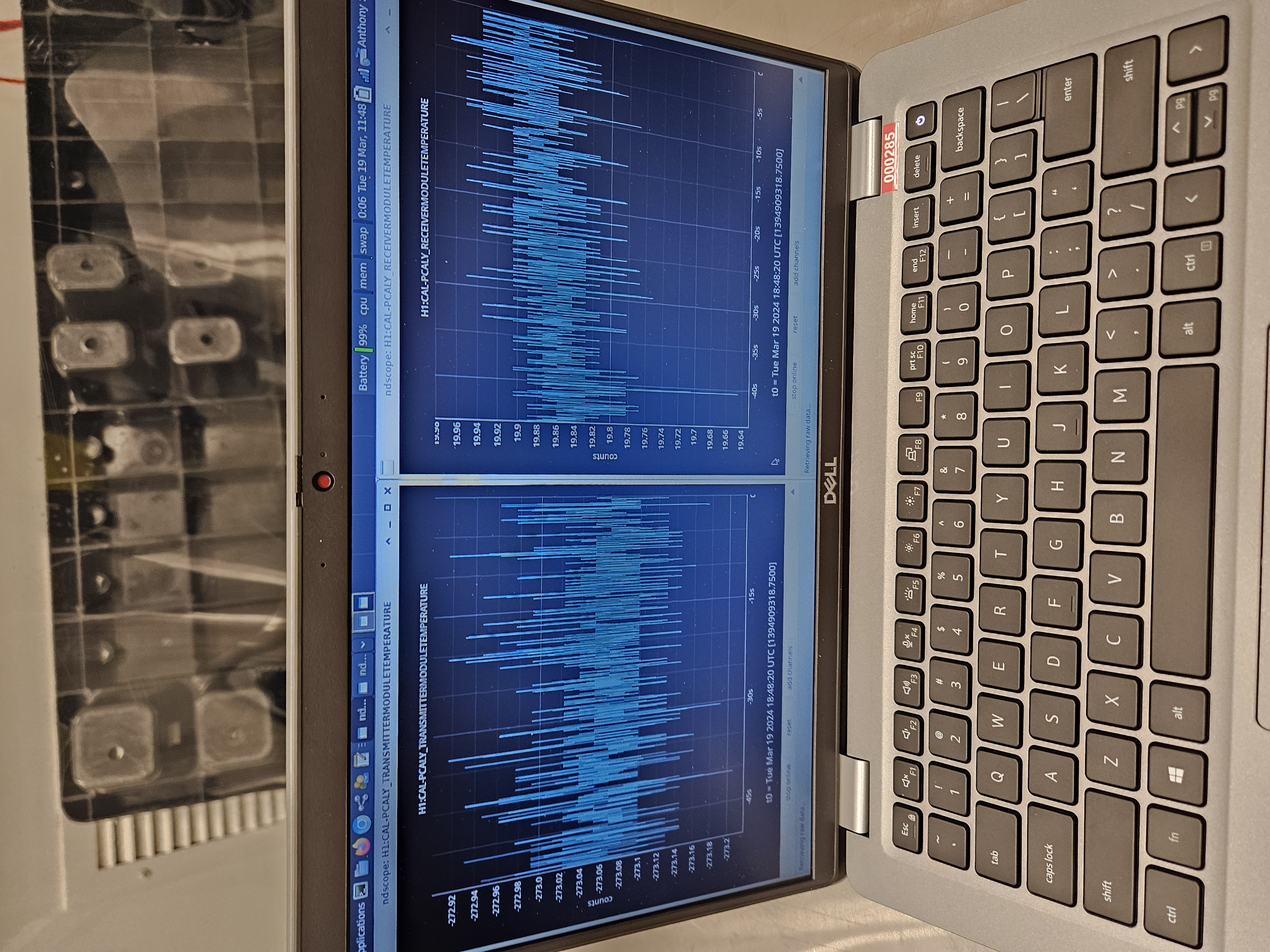
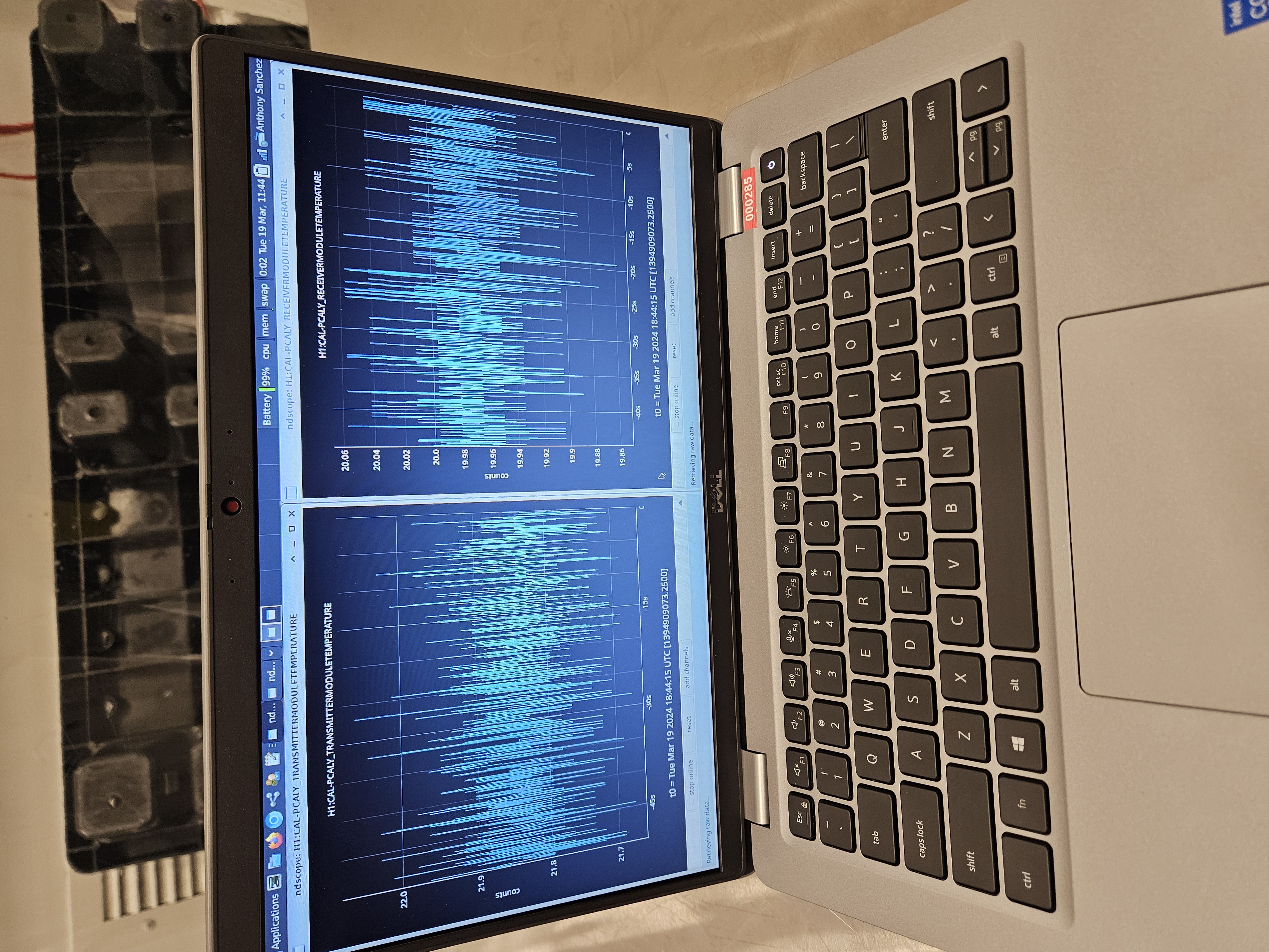
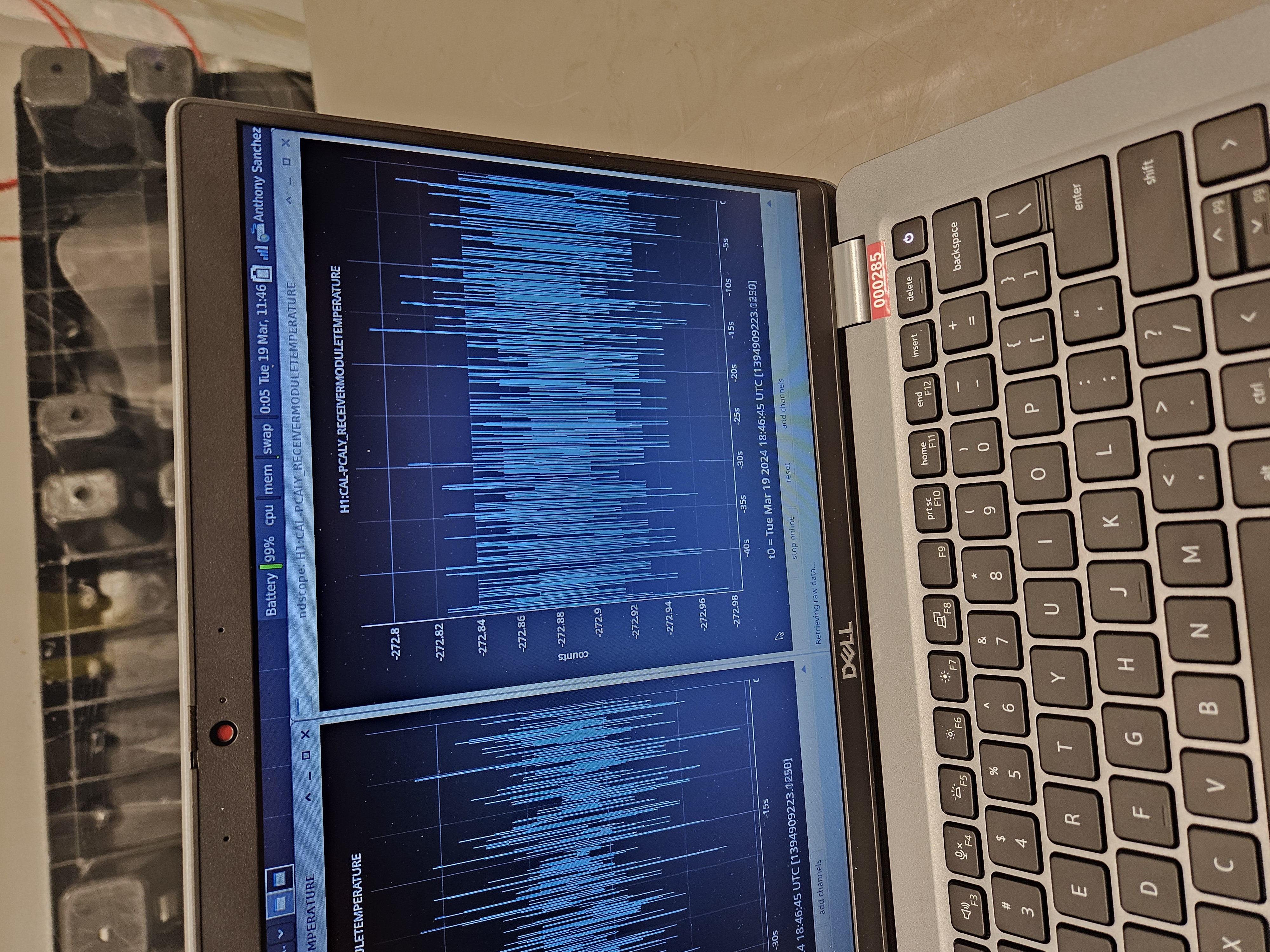
Also Fil and I went back to EY to test the PCAL Temperature channels.
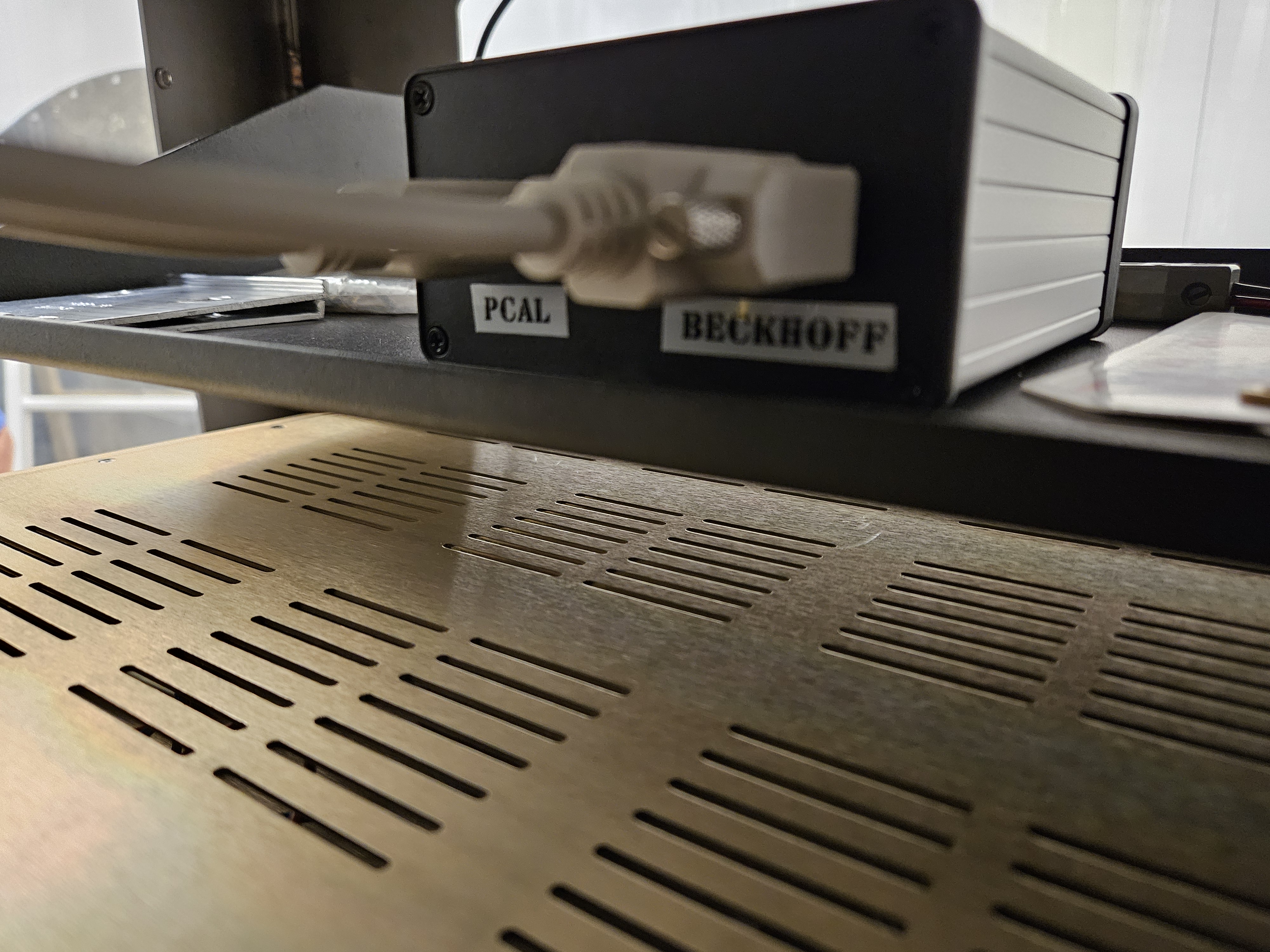
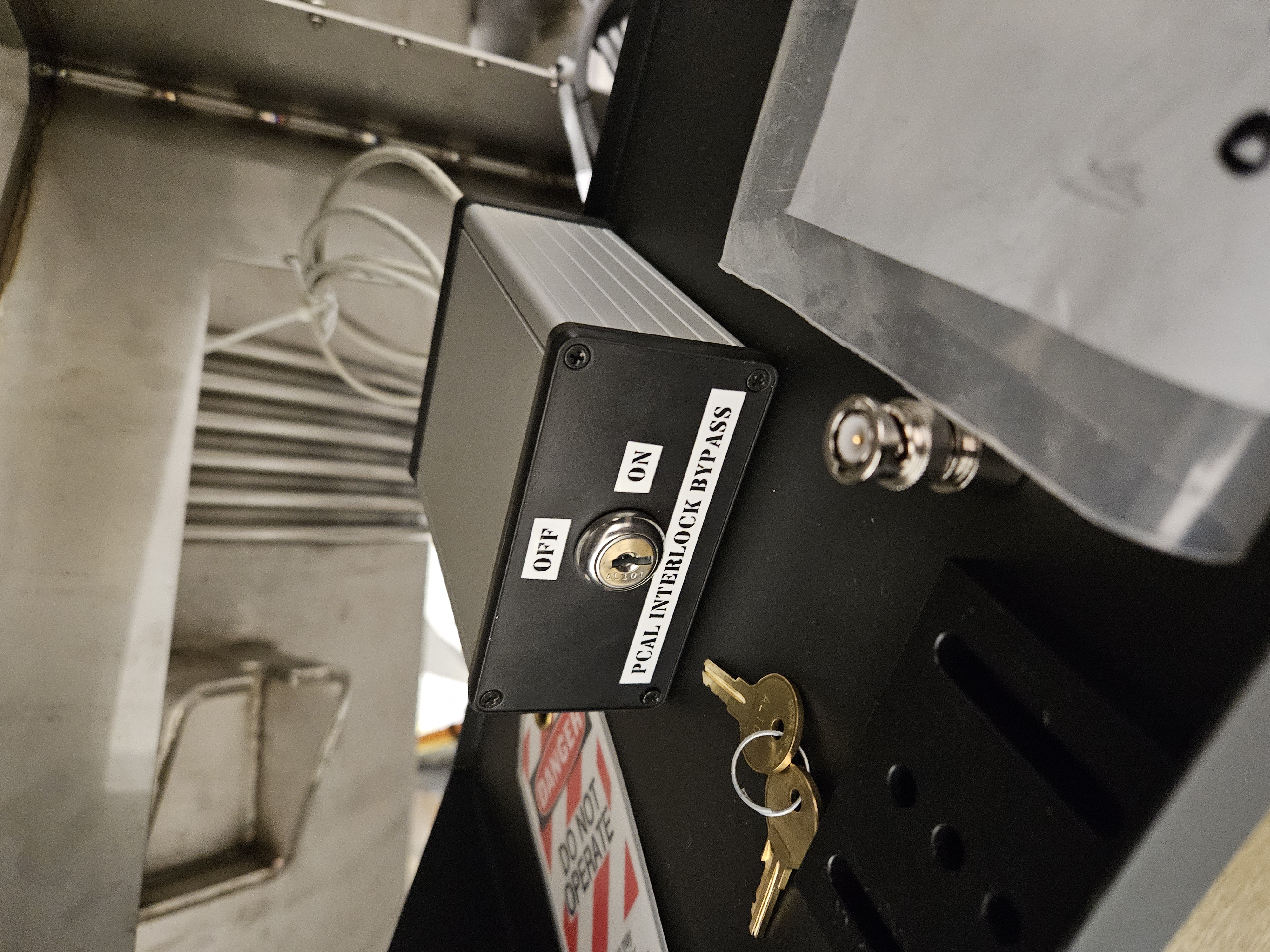
This time Fil and I went down and Turn ON the PCAL enclosure bypass and then pulled the PCAL cable out of the back of the PCAL Enclosure bypass Chassis.
GPS Time 1394909058
The ndscope of these channels did not appear any cleaner when we unplugged the PCAL cable out of the back of the PCAL Enclosure bypass Chassis.
The ndscope of these channels did not appear any cleaner when we unplugged the Rx Module Temperature cable from the front of the PCAL Chassis. But the Rx Temp did go to 0.
The ndscope of these channels did not appear any cleaner when we unplugged the Tx module Temperature cable from the front of the PCAL Chassis. But Tx Temp did go to 0.
A PCAL End Station Measurement was done on the Spring Equinox (Mar 19th 2024), the PCAL team( Dripta B. & Tony S.) went to ENDY with Working Standard Hanford aka WSH(PS4) and took an End station measurements.
The ENDY Station Measurement was carried out according to the procedure outlined in Document LIGO-T1500062-v15, Pcal End Station Power Sensor Responsivity Ratio Measurements: Procedures and Log, and was completed by 10:30 am.
Measurement Log
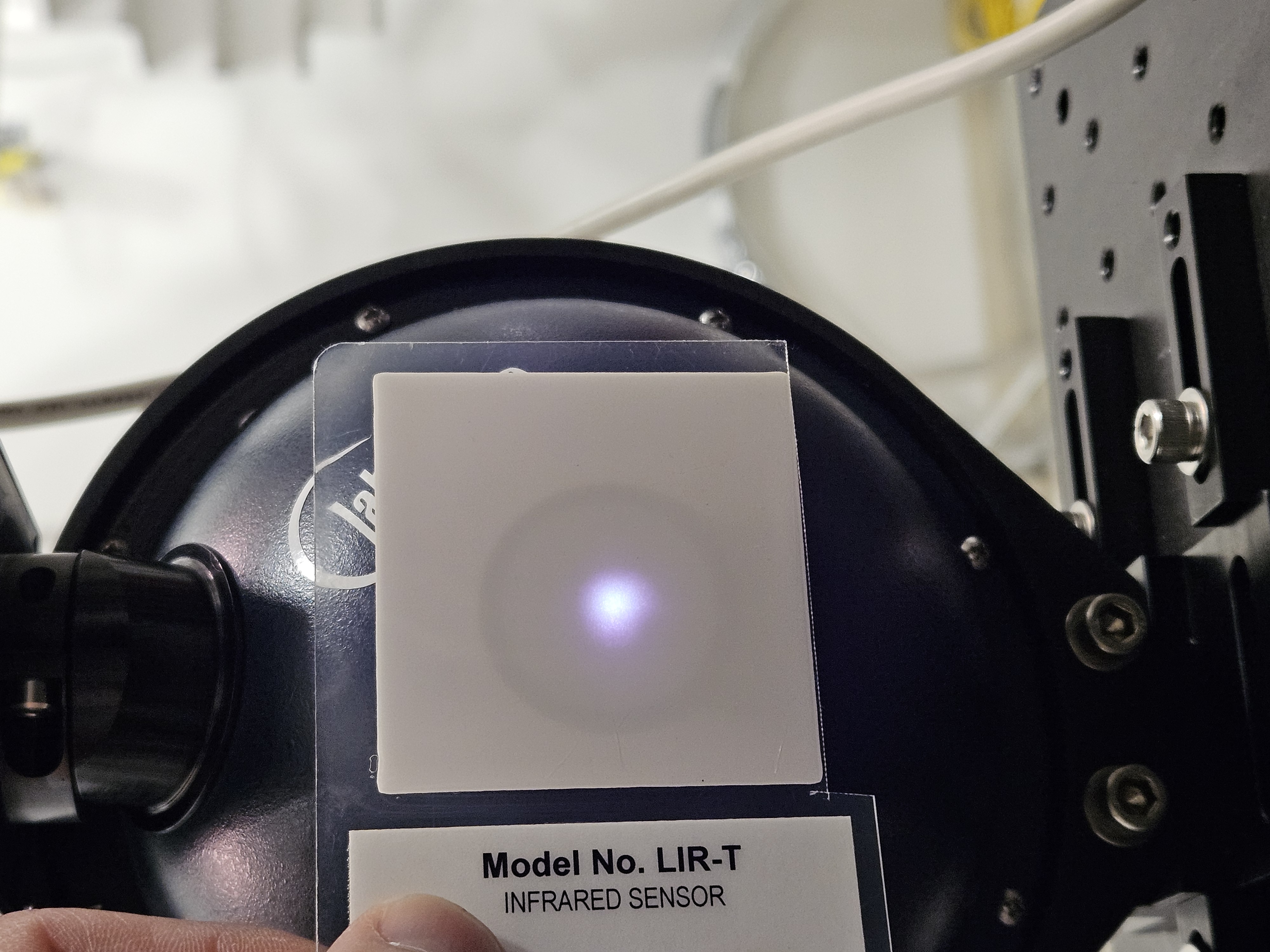
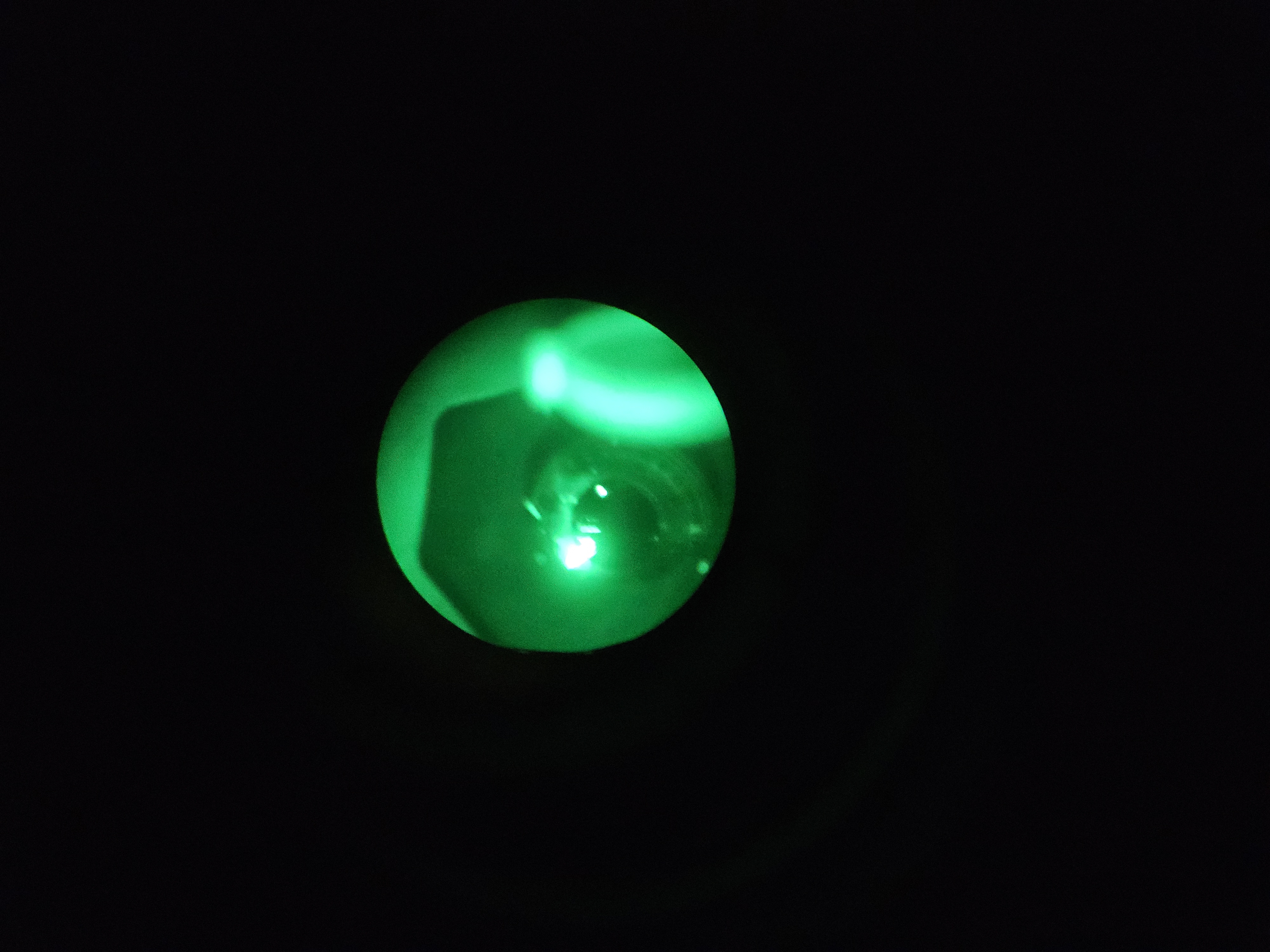
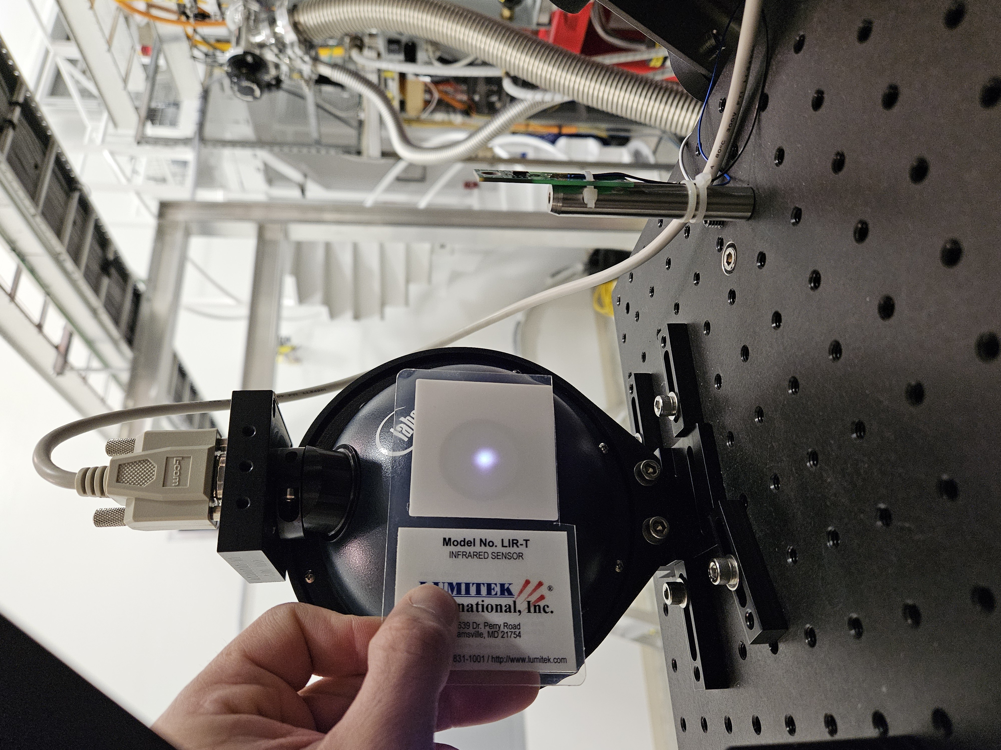
First thing we did is take a picture of the beam spot before anything is touched!
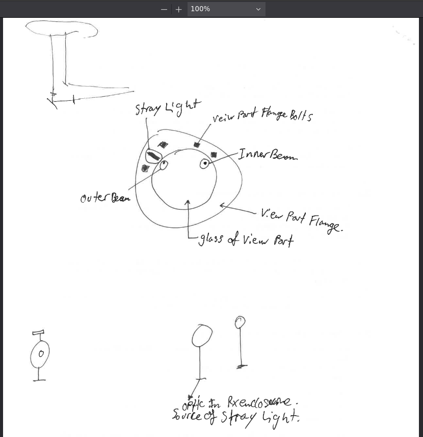
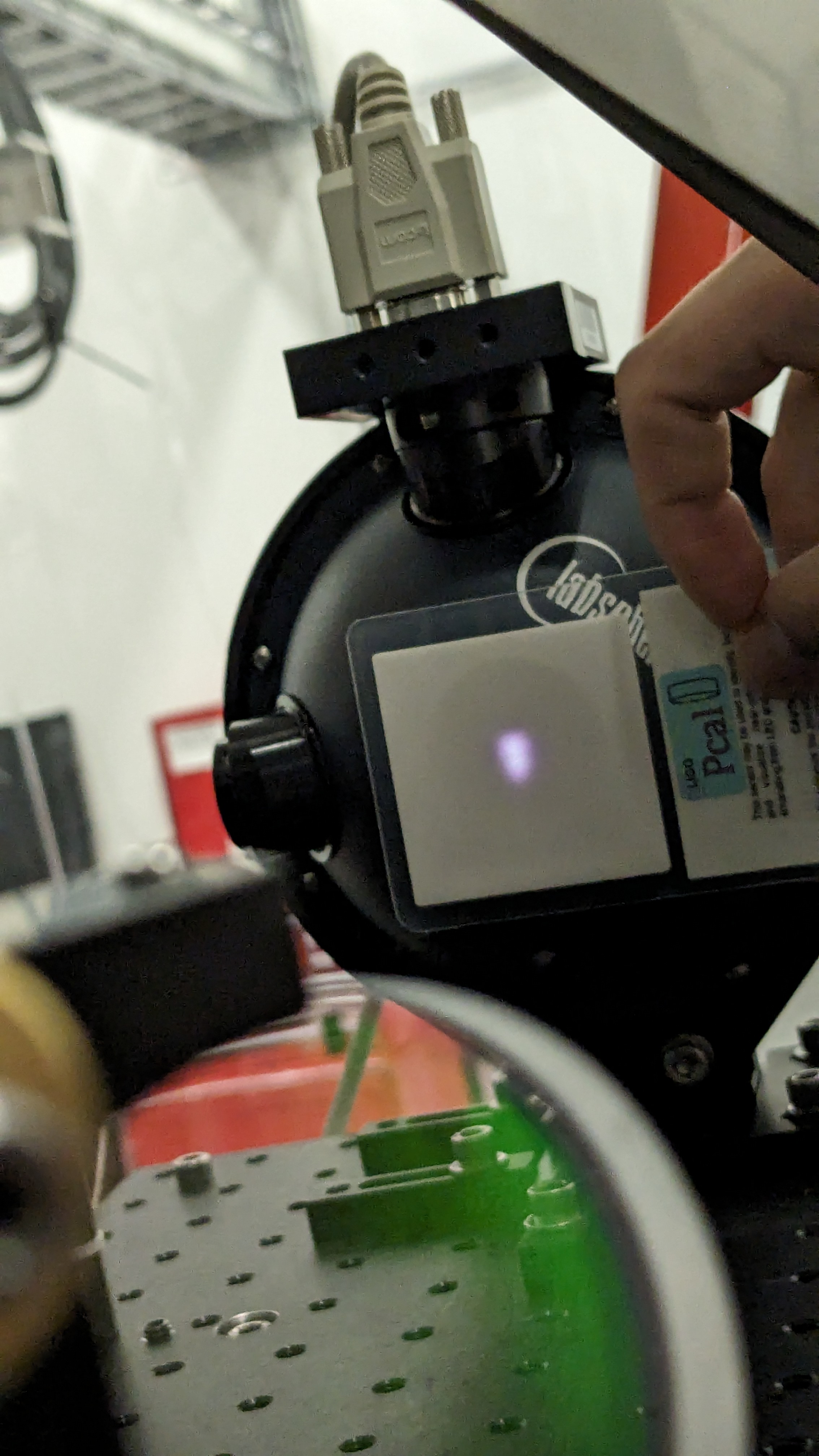
On this particular trip I not only took a pic of the beam spot on the Rx Sensor, but I took pictures of the viewport that the PCAL beams come out of on the Rx side. I was hoping to just document where the beams can be seen on the glass. As you can see there is a surprising amount of light on the flange that hold the viewport glass. This light seems to be a reflection from the optics we have in the RX enclosure. I was able to identify which beam on the glass is which. Please see my cartoonish diagram on the back of the Log document above for more details.
Martel:
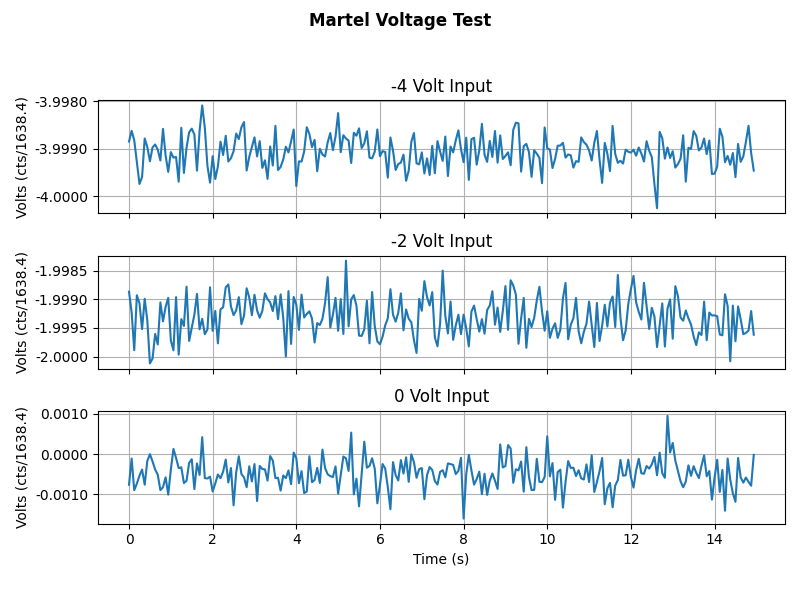
Martel Voltage source applies voltage into the PCAL Chassis's Input 1 channel. We record the GPStimes that a -4.000V, -2.000V and a 0.000V voltage was applied to the Channel. This can be seen in Martel_Voltage_Test.png . We also did a measurement of the Martel's voltages in the PCAL lab to calculate the ADC conversion factor, which is included on the above document.
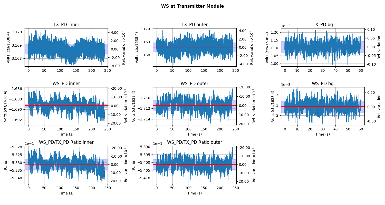
Plots while the Working Standard(PS4) is in the Transmitter Module during Inner beam being blocked, then the outer beam being block, followed by the background measurment: WS_at_TX.png.
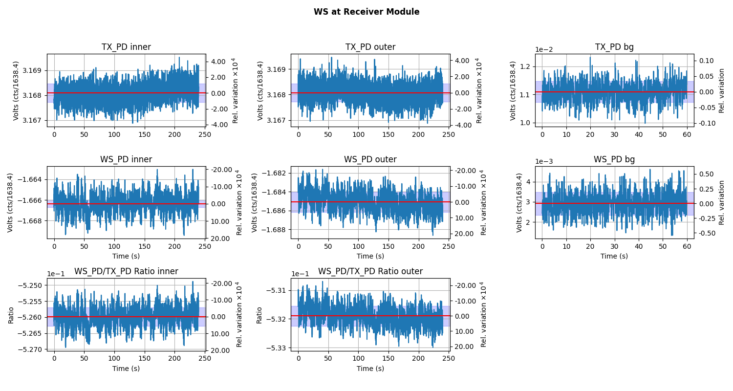
The Inner, outer, and background measurement while WS in the Receiver Module: WS_at_RX.png.
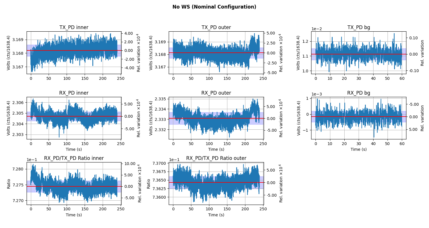
The Inner, outer, and background measurement while RX Sphere is in the RX enclosure, which is our nominal set up without the WS in the beam path at all.: TX_RX.png.
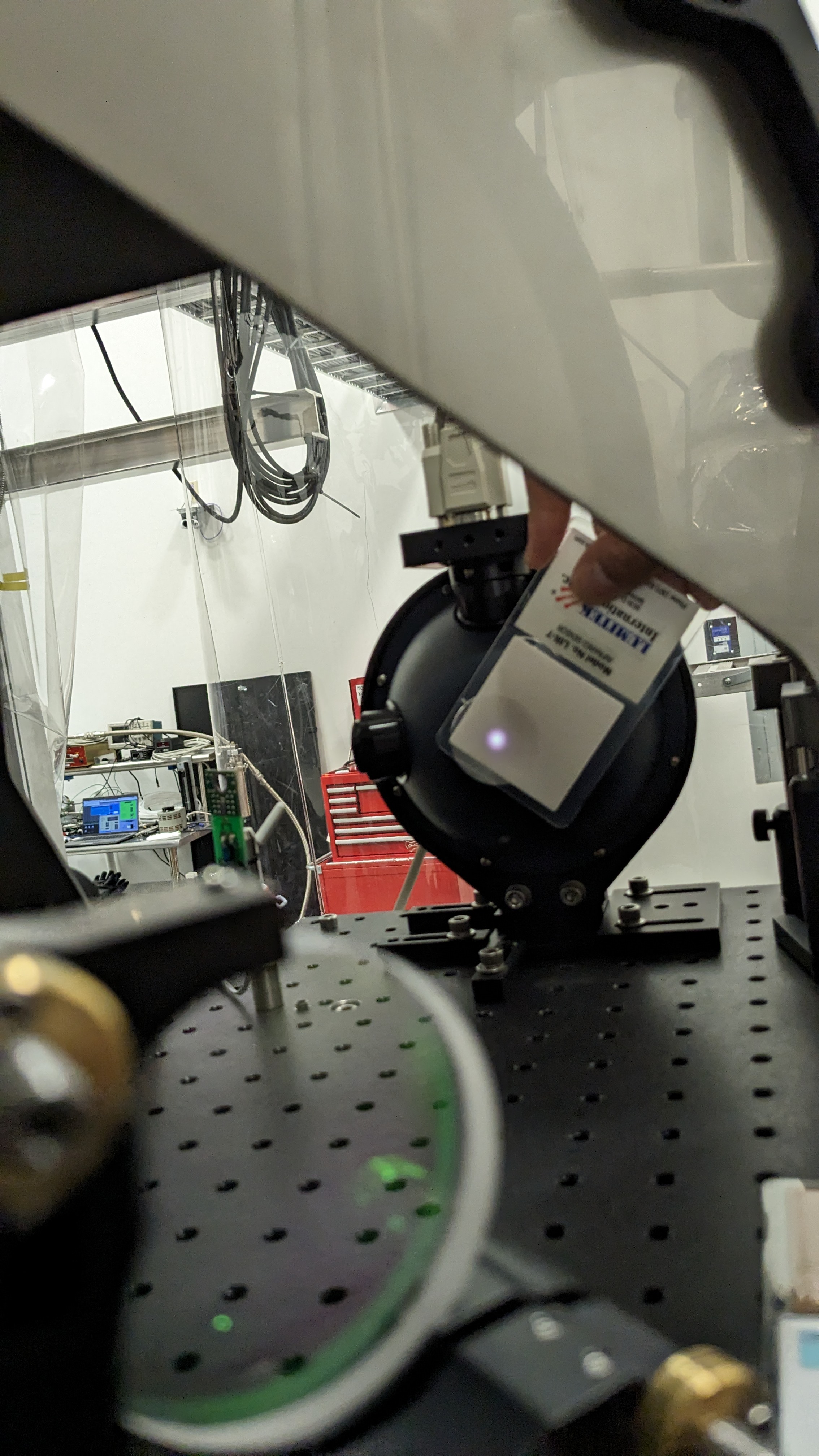
The last picture is of the Beam spots after we had finished the measurement.
All of this data is then used to generate LHO_ENDY_PD_ReportV2.pdf which is attached, and a work in progress in the form of a living document.
End Station data and Analysis has been commited to the SVN :
https://svn.ligo.caltech.edu/svn/aligocalibration/trunk/Projects/PhotonCalibrator/measurements/LHO_ENDY/
PCAL Lab Responsivity Ratio Measurement:
A WSH/GSHL (PS4/PS5)FrontBack Responsivity Ratio Measurement was ran, analyzed, and pushed to the SVN.
The analysis of this measurement produces 4 PDF files which we use to vet the data for problems.
raw_voltages.pdf
avg_voltages.pdf
raw_ratios.pdf
avg_ratios.pdf
Obligitory BackFront PS4/PS5 Responsivity Ratio:
PCAL Lab Responsivity Ratio Measurement:
A WSH/GSHL (PS4/PS5)BF Responsivity Ratio measurement was ran, analyzed, and pushed to the SVN.
The analysis of this measurement produces 4 PDF files which we use to vet the data for problems.
raw_voltages2.pdf
avg_voltages2.pdf
raw_ratios2.pdf
avg_ratios2.pdf
Lab data and analysis can be found here:
https://svn.ligo.caltech.edu/svn/aligocalibration/trunk/Projects/PhotonCalibrator/measurements/LabData/PS4_PS5/
This adventure has been brought to you by Dripta B. & Tony Sanchez.
Jason, Filiberto, Fernando.
Per the WP11763
Motor/Brake cable identification was perfromed for the TIMX/ITMY/BS OPLevers. The provisional Medm was tested as well. We took advantage of this opportunity to complete the internal wiring in the BS OPLEver with the inclusion of the RJ9 patches.
The WP will remain open to perform the activity in ETMX/ETMY next Tuesday.
ETMX and ETMY OPLever motors and brakes were identified. Medm tested and Beckhoff software updated with the right directions found.
WP11743 SUS DACKILL removal
Jeff, Oli, Dave:
SUS model modifications to remove DACKILL parts and install new WD systems was made to the corner station BSCs (ITMX, ITMY, BS).
New models were installed for h1susitmx, h1susitmy, h1susbs, h1susitmpi, h1isiitmx, h1isiitmy, h1isibs. DAQ restart was required.
DAQ Restart
Dave:
DAQ was restarted for model changes, no EDC restart. 0-leg restart 10:52, 1-leg restart 10:57. Both required GDS second restarts for channel list sync. No issues.
CDS SDF WAP back to O4 configuration
Oli, Dave:
The CDS WiFi WAPs are back to their O4 configuration (all OFF except MSR). I have accepted the SDF diffs.
(Betsy, Camilla)
We performed an LVEA closeout walk thru after today's Tues Maint window (and the previous weeks of vent and pump work).
Nutsinee helped tidy up the Squeezer rack power cords and auxilliary equipment which was plugged in and around the floor. There is still a spectrum analyzer plugged in and powered up at the rack since there will be some more work there throughout the Eng Run starting tomorrow.
All HEPIs, cleanrooms, and ISC tables in proper shape. Camilla unplugged the high lift which was still on a charger.
The high bay door to the CER on the way into the LVEA is still open, had been open during O4a legacy of some old HVAC issue. However, Fil reports that the HVAC issue should be solved so we have closed the door now (to aid in any further electronic noise near the inner LVEA walls).
Paging system and phones all unplugged.
Oli turned off the WIFI hubs remotely.
Staff out, lights in the LVEA are off.
RickS, Daiki Tanabe, Francisco Llamas
This morning we moved the Xend pcal beams to center them on the input aperture target of the pcal Rx power sensor. This is the initial configuration for a series of pcal beam position movements to test the X/Y comparison ratio. Notes for reference attached as pdf.
09:00 local: Turned off the ALS green laser.
The outer beam was initially off-center, a bit below the target. The inner beam seemed to be centered. See first image (PXL_20240319_162539223) attached. We used the Rx power sensor, H1:CAL-PCALX_RX_PD_WATTS_OUTMON, to maximize the input power from each beam, one at a time. The first beam we maximized was the inner beam, going from 0.211 W to 0.223 W. Next, we maximized the outer beam. We unintentionally moved the outer beam to the lower target, 5 mm below center and found a maximum at 0.209 W. The total power with the target on was 0.432. This "accident" happened because no one was supervising the direction the beam was moving on the Rx input port while the mirror was being moved. The maximum value of the outer beam centered on the target was found at 0.209 W. The total power with the target on was 0.432. Our "accident" leans towards laser power measurement being independent of beam location, within a tenth of a percent. The power, once the target was removed, was 0.491 W. See second attached image (PXL_20240319_170413484) for the beam location after we finished our configuration.
10:20 local: Turned on the ALS green laser.
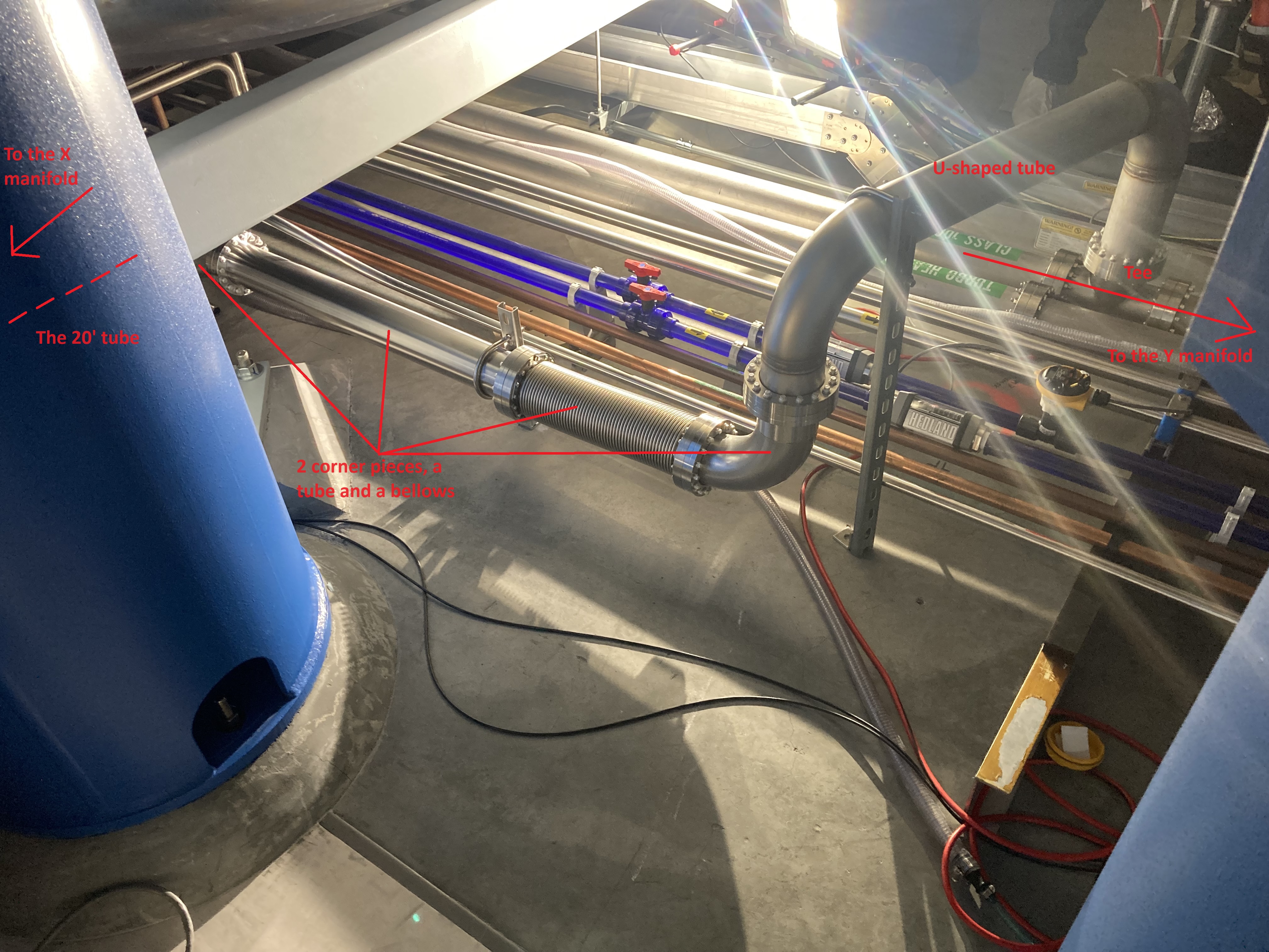
The connection of the X-manifold purge line to the main purge tubing system in the LVEA was finished today: - A 20' long tube was re-used from the H2 system leftover tubes after it was proven to be clean, to lengthen the X-manifold purge line - In the Y-manifold line, a tee was moved closer to the X-manifold, which was used for the connection - A U-shaped H2 leftover tubing was reused as a connection element over the other tubings and conduits - 2 more corner pieces, a straight tube, and a bellows were purchased to complete the connection This work still needed to be done after the decommissioning of the H2 system, as without this, the X-manifold could not be purged. This line is also essential for the regeneration of CP2 in the future. It was nice work from the vacuum team, the whole thing was done within 2 maintenance periods.
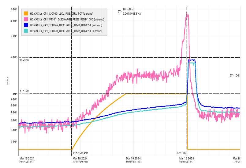
Tue Mar 19 10:10:49 2024 INFO: Fill completed in 10min 45secs
TITLE: 03/19 Day Shift: 15:00-23:00 UTC (08:00-16:00 PST), all times posted in UTC
STATE of H1: Commissioning
OUTGOING OPERATOR: None
CURRENT ENVIRONMENT:
SEI_ENV state: CALM
Wind: 4mph Gusts, 2mph 5min avg
Primary useism: 0.02 μm/s
Secondary useism: 0.19 μm/s
QUICK SUMMARY:
Maintenance today! Looks like we were up for a good number of hours overnight.
Workstations were updated and rebooted. Os packages were updated. Conda package 'gwinc' was updated to 0.6.0.
Naoki, Camilla, Evan, Sheila, Julian, Nutsinee
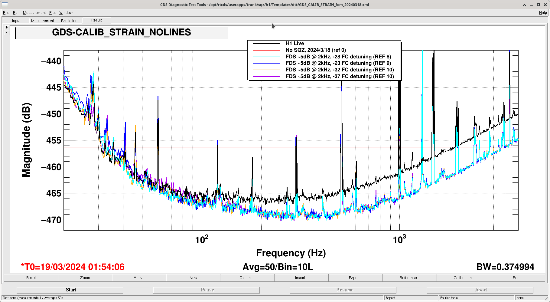
Many things happened with the squeezer this afternoon. A quick summary is we are back to 5 dB at kHz and we should be able to do this repeatedly. No PSAMs adjustment required at this time.
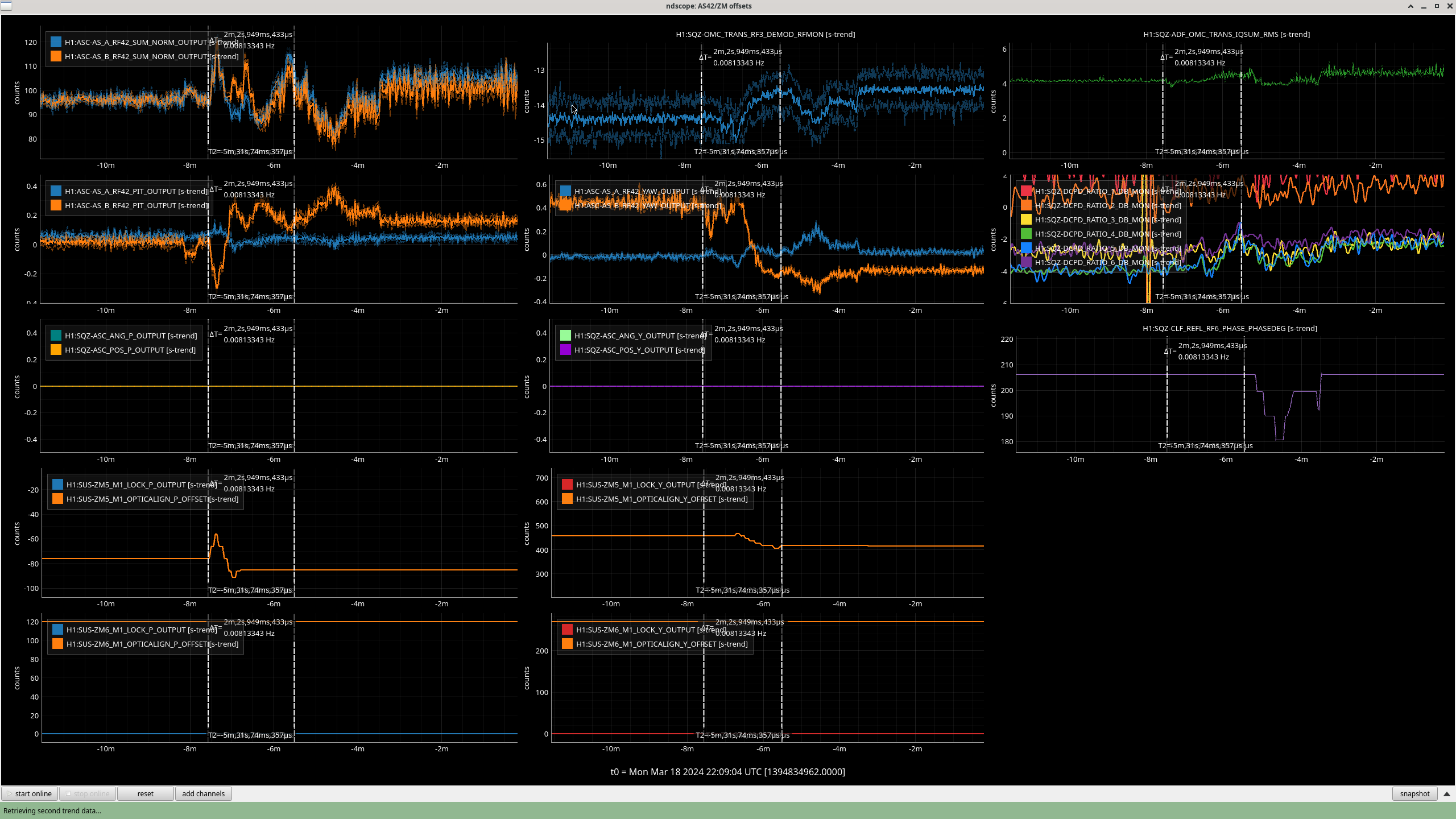
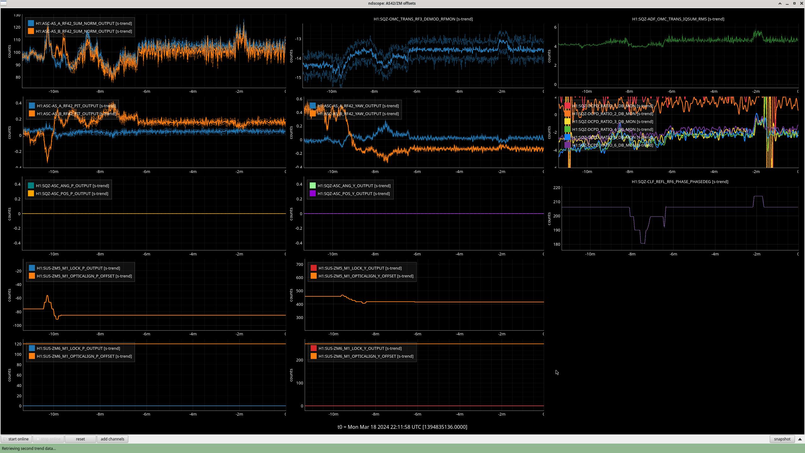
- When the IFO relocked this afternoon we adjusted ZM5 alignment to optimize ADF trans signal. By doing so we improved both the RF3 and the 42. However this made squeezing worse.
- We adjusted the SQZ angle. We couldn't make it better so we went the other way. This made squeezing worse and ADS TRANS went up with it. Note that this is the IQSUM channel. We didn't think that was a sensible behavior but we've seen it before.
- Sheila and Julian then optimized the crystal tempeature. The NLG for today was 17.3.
- Naoki measured the SQZ IFO sensing matrix. We found a big cross coupling between ZM5 P to AS42 B Y. Other than then everything else was sensible. A new improved sensing matrix has been implemented.
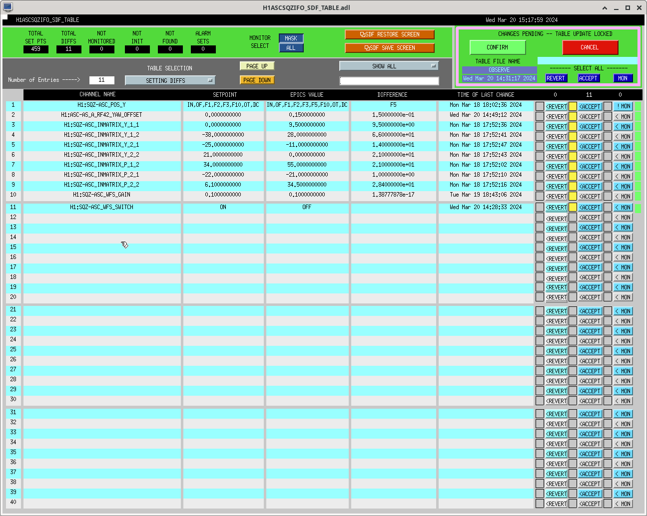
- We lost hours tracking down why the filter cavity failed to lock on green. A reminder to check SDF next time we run into mysterious problems.
- After everything went back to normal we recovered 5 dB of squeezing. DARM plot said so. BLRMS seemed slightly off. We tried turning the ASC loop off and optimizing the ZM alignment by hand to see if we could do any better than the loop. We couldn't. SQZ IFO ASC loop now works as it should.
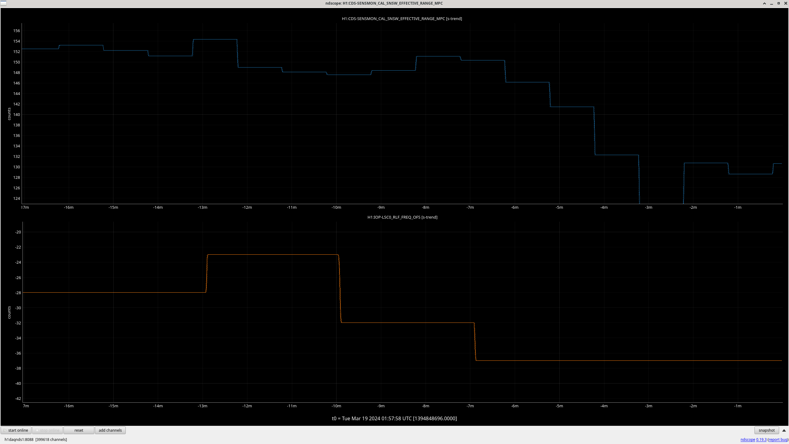
- We also optimized the filter cavity offset. Mostly to double checked that we were sitting at a good place. An offset of -28 (where we started) gave the best squeezing at low frequency.
We haven't got to increase CLF power today.
After a new CLF VCO installed we should revert the CLF sign to make sure everything was the same as before. In theory this shouldn't do anything.
Naoki Nutsinee
We changed "fcgs_trans_lock_threshold" to 120 today so FC wouldn't lock on higher order mode. The filter cavity was having trouble getting pass GR VCO lock so we have now reduced this power back to 80.
Accepted the new ASC_INMATRIX settings in sdf, see attached. Aslo accepted ASC_POS_Y's new minus sign and AS_A_RF42_YAW_OFFSET.
Accpeted the SQZ_ASC WFS as OFF. As decided, we will start the ER with SQZ ASC IFO off.
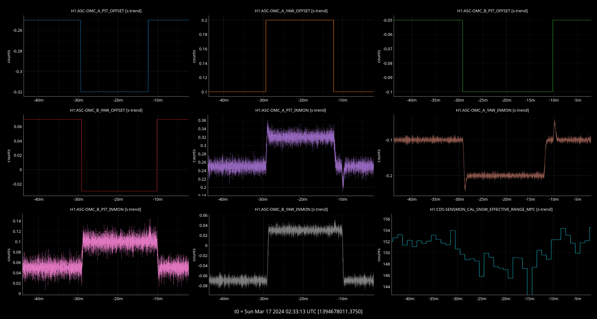
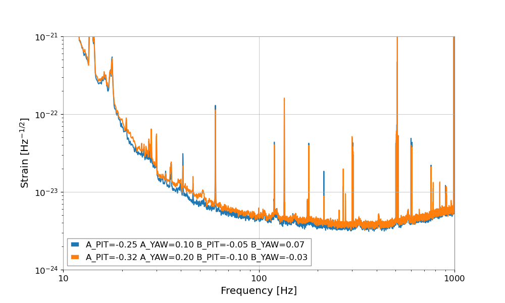
I tested again the OMC aligment with low frequency lines, as in 76335
It looks like there is still some modulation of the DARM line amplitude at 410.x Hz. There is also some effect on the pitch jitter line amplitude, but no effect on the yaw jitter line amplitude.
New offsets that simultaneously make the DARM calibration line maximum and the pitch jitter minimum:
| Old | Diff | New | |
|---|---|---|---|
| A PIT | -0.25 | -0.07 | -0.32 |
| A YAW | 0.1 | 0.1 | 0.2 |
| B PIT | -0.05 | -0.05 | -0.1 |
| B YAW | 0.07 | -0.01 | -0.03 |
I put those offsets in. The range dropped. So they are not good. I don't understand why. I reverted them. The range went back. A step in the other directions did not change the range much, but KAPPAC dropped.
I checked that indeed GDS-CALIB_STRAIN was worse with the alignment offsets that made the range lower
Disregard the previous plot, there were two glitches in the data. DARM is slightly worse, but as significantly as thought.
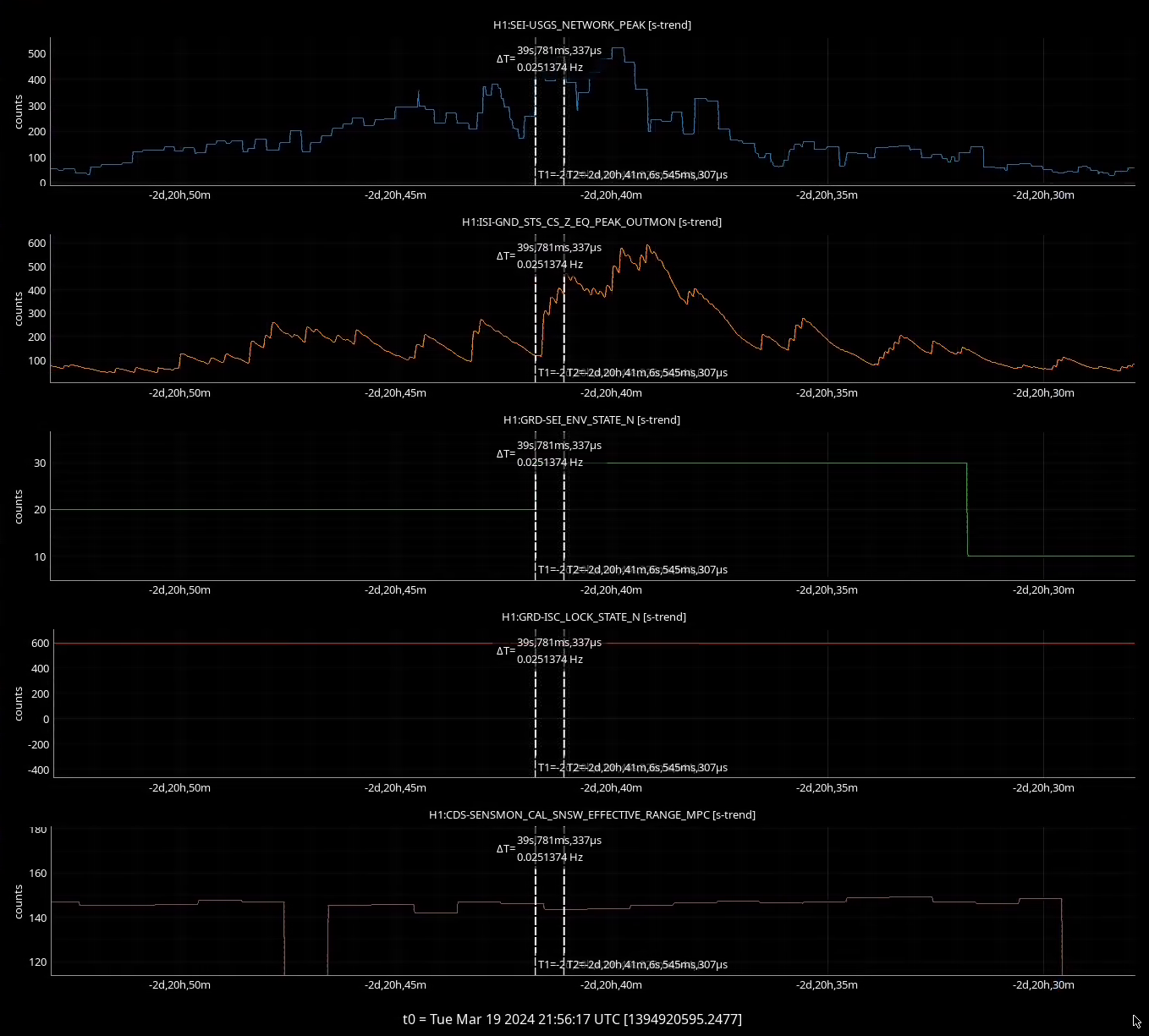
This has been the plan for a while, to add Picket Fence to the SEI_ENV earthquake transition. I more or less copied the logic for the PEAKMON tests that we use for the earthquake transitions and appliedt that to the network peak channel for picket fence. So if the network peak channel goes above 800nm/s that will cause SEI_ENV to transition to the appropriate earthquake state. I have convinced myself that the worst case scenario is we just won't transition early because of network lag in picket fence. I haven't seen any cases so far where a signal in picket fence would cause us to unnecessarily transition. I have seen many cases where picket fence gave ~30sec of early warning. The code is pretty simple and only got added to two or three state test in SEI_ENV, so if it breaks something it will be easy to remove.
There was a smaller earthquake over the weekend where SEI_ENV successfully transitioned based on the picket fence. Looks like there was a seismon alert, then picket fence and peakmon started seeing motion. Picket fence hit transition threshold first, SEI_ENV transition to earthquake mode. Worked more or less as hoped.
Attached trends show that picket fence triggered a transition about 40 seconds before peakmon would have, denoted by the gap between to T1 and T2 markers. IFO stayed locked, range didn't seem to be effected by this.
Guardian log details:
2024-03-17_01:02:20.270775Z SEI_ENV [CALM.run] Seismon active
2024-03-17_01:02:20.323350Z SEI_ENV JUMP target: SEISMON_ALERT
2024-03-17_01:02:20.323922Z SEI_ENV [CALM.exit]
2024-03-17_01:02:20.384479Z SEI_ENV JUMP: CALM->SEISMON_ALERT
2024-03-17_01:02:20.384479Z SEI_ENV calculating path: SEISMON_ALERT->AUTOMATIC
2024-03-17_01:02:20.386365Z SEI_ENV no path from SEISMON_ALERT->AUTOMATIC
2024-03-17_01:02:20.387211Z SEI_ENV executing state: SEISMON_ALERT (20)
2024-03-17_01:02:20.392798Z SEI_ENV [SEISMON_ALERT.enter]
2024-03-17_01:02:20.396653Z SEI_ENV [SEISMON_ALERT.main] timer['wait_for_eq'] done
2024-03-17_01:02:20.396879Z SEI_ENV [SEISMON_ALERT.main] timer['wait_for_eq'] = 0
2024-03-17_01:12:09.400662Z SEI_ENV [SEISMON_ALERT.run] Seismon expired, waiting for 10min.
2024-03-17_01:12:09.401201Z SEI_ENV [SEISMON_ALERT.run] timer['wait_for_eq'] = 600
2024-03-17_01:14:30.963091Z SEI_ENV [SEISMON_ALERT.run] Picket fence active, moving to earthquake state
2024-03-17_01:14:31.022819Z SEI_ENV JUMP target: EARTHQUAKE
2024-03-17_01:14:31.022819Z SEI_ENV [SEISMON_ALERT.exit]
2024-03-17_01:14:31.073148Z SEI_ENV JUMP: SEISMON_ALERT->EARTHQUAKE
2024-03-17_01:14:31.075567Z SEI_ENV calculating path: EARTHQUAKE->AUTOMATIC
2024-03-17_01:14:31.076049Z SEI_ENV no path from EARTHQUAKE->AUTOMATIC
2024-03-17_01:14:31.077111Z SEI_ENV executing state: EARTHQUAKE (30)
2024-03-17_01:14:31.080344Z SEI_ENV [EARTHQUAKE.enter]
2024-03-17_01:14:31.085106Z SEI_ENV [EARTHQUAKE.main] ezca: H1:GRD-SEI_CONF_REQUEST => EARTH_QUAKE
2024-03-17_01:14:31.086931Z SEI_ENV [EARTHQUAKE.main] timer['calm'] done
2024-03-17_01:14:31.087026Z SEI_ENV [EARTHQUAKE.main] timer['calm'] = 0
2024-03-17_01:14:31.149187Z SEI_ENV [EARTHQUAKE.run] timer['calm'] = 600
2024-03-17_01:24:31.149524Z SEI_ENV [EARTHQUAKE.run] timer['calm'] done
2024-03-17_01:24:31.209025Z SEI_ENV [EARTHQUAKE.run] Low ground for 10min, going back to CALM
2024-03-17_01:24:31.264932Z SEI_ENV JUMP target: CALM
2024-03-17_01:24:31.267722Z SEI_ENV [EARTHQUAKE.exit]
2024-03-17_01:24:31.329422Z SEI_ENV JUMP: EARTHQUAKE->CALM
2024-03-17_01:24:31.329664Z SEI_ENV calculating path: CALM->AUTOMATIC
2024-03-17_01:24:31.329812Z SEI_ENV no path from CALM->AUTOMATIC
2024-03-17_01:24:31.331824Z SEI_ENV executing state: CALM (10)
2024-03-17_01:24:31.332473Z SEI_ENV [CALM.enter]