Summary:
We restarted the alignment work. The angle and/or the position of the new OMC relative to the cage is significantly different from the old one, and we had to mechanicaly rebalance not just the OMC, but OM3 and OM2 too, and rotate the cage of OM3. We'll see if these were good enough tomorrow.
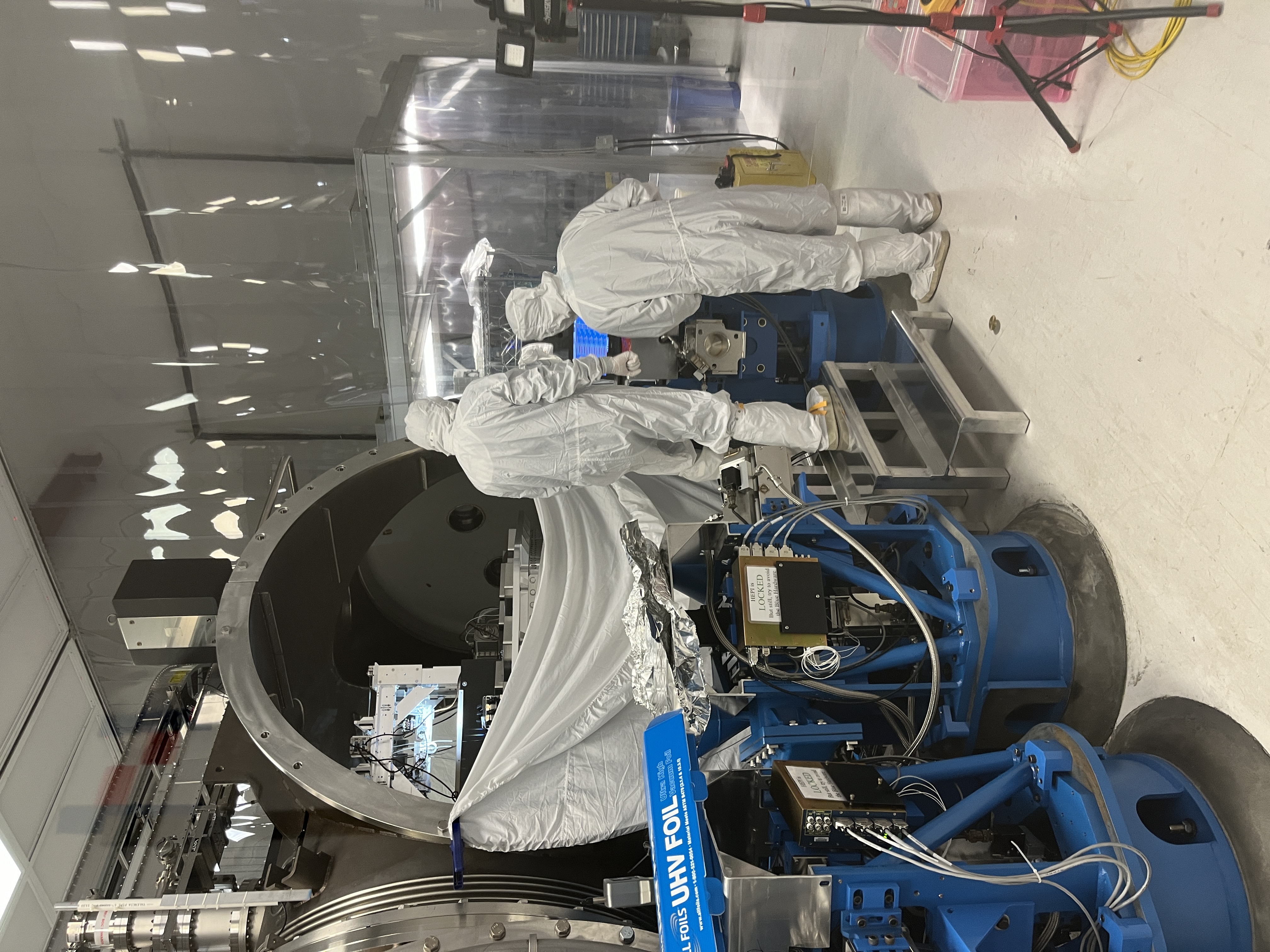
1. Rebalancing the OMC
Yesterday, we rebalanced the OMC, the beam was on both of OMC QPDs but we didn't have time to touch up OM1 and OM2 to center the beam on OMC QPDs. This morning we centered the QPDs and relieved the PIT offset of the OM3 as much as I could by using OM1 and OM2. Then we did another push of the balance mass, recentered the QPDs, and relieved PIT offsets of OM1/2/3 such that everybody kind of equally suffer. We ended up doing four iterations of this in total.
Following is the PIT/YAW offset slider values (ASC output to OM1/OM2 due to earlier WFS centering was already folded into these numbers).
Note1: OMn (n=1/2/3) sliders are not calibrated. Due to different EUL2OSEM matrix, OM2 apparent "range" for the sliders is about a factor of 1.7 larger than OM1 and OM3 (i.e. if you compare OM1 and OM2 coil output, the latter has a factor of 1.7 smaller output than the former given the same slider offset).
Note2: By "centering", we really mean centering w/o offsets. Since the position of the QPDs relative to the cavity mode differs from one assembly to another, there's no reason to assume that the good QPD offsets for the new OMC will be the same as the old one.
| |
OM1 PIT/YAW |
OM2 PIT/YAW |
OM3 PIT/YAW |
|
Offsets that worked for the Old OMC with WFS centering ON yesterday (note: OM2 was railing periodically.)
|
1023/-403 |
-1440/-3751 |
230/-930 |
|
New OMC before rebalancing yesterday (note: OMC QPDs couldn't be centered at all no matter what. OM2 was railing periodically.)
|
1663/-519 |
-2388/-2948 |
3200/0 |
| After the 4th round of OMC rebalancing. QPDs are nicely centered. |
973/-64 |
713/-1649 |
-70/1269
|
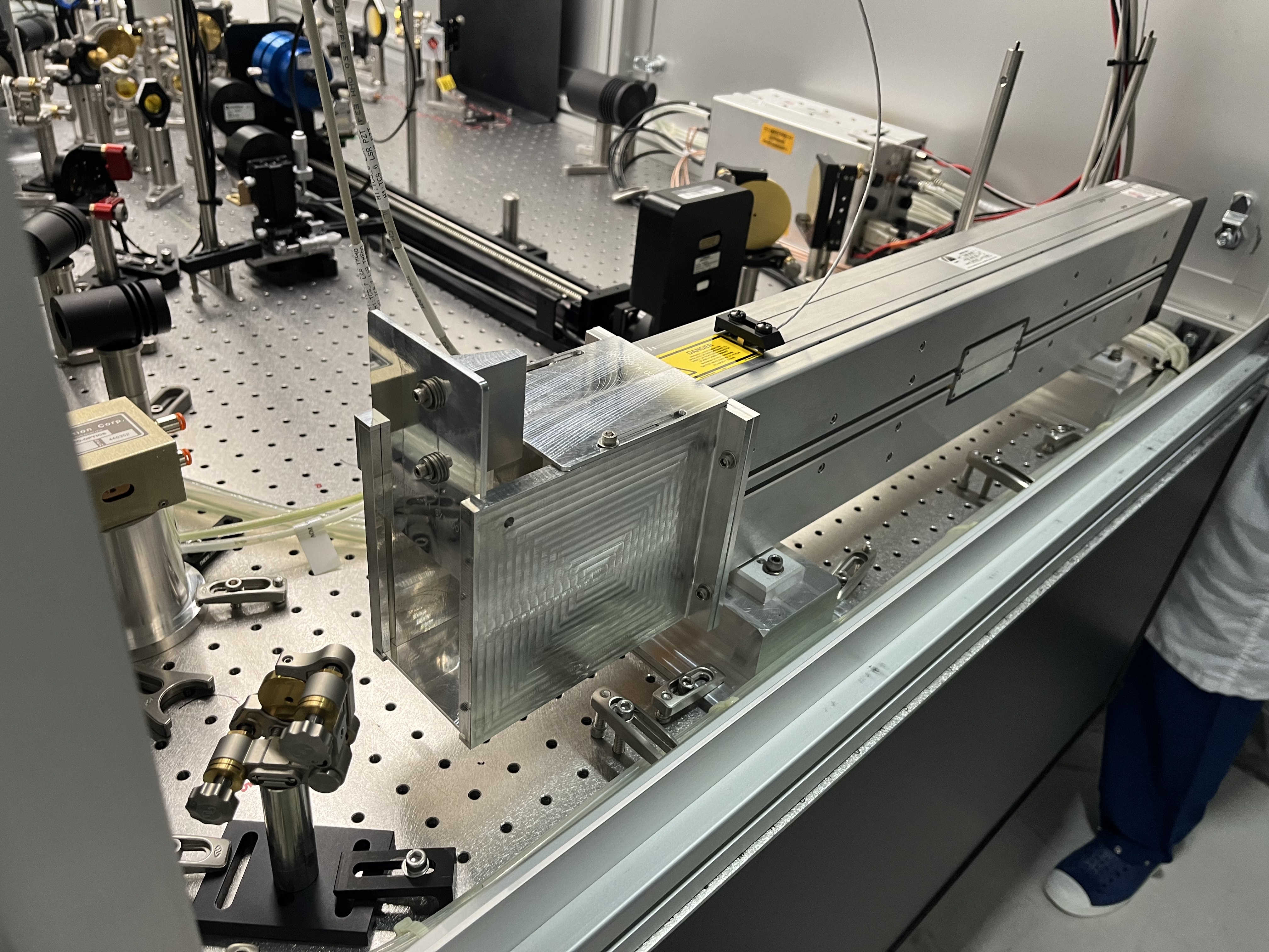
2. Beam height measurement, beam centering on OMs
At this point Koji measured the beam height at OM1, OM2 and OM3.
The beam was about 3/64" or about 1mm too high on OM1 (it was 5mm higher than 4" in the past) but it was too low on OM2 by ~16/64" or about 6mm. It quickly went up from OM2 to OM3 where the beam height was about 2/64" or about 0.8mm too low. The beam was clearing the input hole of the OMC shroud cleanly, and the OMCR beam was level.
These meant that OM2 was excessively tilted up and OM3 excessively down, both mechanically. Koji and I agreed that this is most likely due to the difference in angle for the old and the new OMC.
1/4" mis-centering on OM2 sounded too much to ignore to me, so we decided to bring the beam up at OM2 by using OM1 bias, and mechanically relieve the PIT of OM2/OM3 and YAW of OM3.
We're done with the 1st round of mechanical relieving. We adjusted OM2 PIT. We adjusted OM3 PIT and rotated OM3 cage for YAW while making sure that the beam is at least partially visible on both of the QPDs. After centering QPDA, the following shows the numbers as of now.
| |
OM1 |
OM2 |
OM3 |
| PIT/YAW offset |
0/-64 |
213/-1649 |
200/-539 |
|
Beam height (relative to the nominal height of 4")
|
3/64" |
-2/64" |
-2/64" |
Overall, this looks to be a good improvement, but the beam is still hitting QPDB at the edge. We still have to see if it's possible at all to center both QPDs without further mechanical relief.
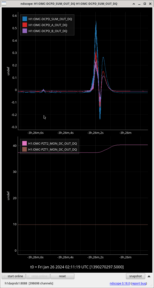
3. PZT and DCPD electronics are working
Koji scanned the OMC PZT and saw flashing on the DCPD A as well as B. PZT as well as the DCPD preamp are working.
Remaining tasks:
Center the OMC QPDs using mostly OM2 and OM3. If further mechanical relief is required, do.
After the OMC QPDs are centered, confirm that OMCR path is still reasonably level. Center the beam on the OMCR DCPD.
Center the AS_A and AS_B.
I don't know how to confirm that the OMC transmission will still hit the viewport for the camera. We'll try to use the card and the viewer combined.
Check the grounding.

