I dont know what caused that lockloss. PI's looked, ground motion and wind looked calm.
ASC signals look like they started moving about a second before LSC signals shook before the lockloss.
ryan.short@LIGO.ORG - posted 16:54, Wednesday 13 December 2023 (74794)
Streamlined SRC Steps During Initial Alignment and Lowered SRX/Y Triggering Thresholds
I've made an update to the INIT_ALIGN Guardian node so that SR2 alignment will now always run before SRC alignment while doing an automated initial alignment (reminder that SR2 alignment does not automatically run when manually going through the initial alignment steps). This allows for the other SRC alignment steps to go uninterrupted; previously when waiting for SRY to catch, INIT_ALIGN would start an SR2 alignment just because a timer expired, which should overall simplify the SRC alignment process and save some time.
We have also been having issues today during the SRY alignment steps where even after lowering the LSC SRCL triggering thresholds (see alog71573 and item 3 of alog71656), SRY will not catch. Since this appears to be a recurring issue, I've lowered the starting upper and lower SRX/Y triggering thresholds in lscparams.py from 0.35 and 0.25 to 0.315 and 0.23, respectively.
All changes are loaded in their appropriate Guardians and updated in svn.
sheila.dwyer@LIGO.ORG - posted 16:46, Wednesday 13 December 2023 - last comment - 23:06, Monday 18 December 2023(74790)
DARM filters switched to a new configuration as a test
Louis, Sheila, Jenne
Today we tried a new DARM loop configuration. We are not implementing this for observing right now, we would need to retune feedforward and redo calibration before we could do that.
There is a new guardian state in ISC_LOCK, called NLN_ETMY. This state turns off feedforward and transitions DARM control to ETMY (L3,L2, L1), it can be used when we are in nominal low noise (but not necessarily from any states before LOWNOISE_ESD_ETMX). This was tested Tuesday morning and today, so it has worked twice.
We set up a new configuration of filters for ETMX. Louis has been using pyDARM to model the DARM crossovers, and we will add more details about these new filters in a later alog. The first attached screenshot shows the configuration that we first transitioned to, without the new boost. This keeps the overall loop similar to our earlier configuration, the main differences are:
we no longer have some low pass and high pass filters in L2 and L3 drivealign (these were left over from a DARM loop design of a very long time ago which wasn't implemented, but relied on a distributed control idea and we've struggled to get rid of them in the past.)
The PUM plant inversion is also moved into L2 drivealign, and we have a crossover filter copied from LLO for the L2/L3 cross over. Now that we have removed the high pass and low pass and put our plant inversion in drivealign, it should be easier to make changes to this loop.
The UIM filters are kept mostly the same, with the plant inversion from L2 copied to L1 to avoid making a change. We would like to change this so that we have more offloading to the UIM, but decided to make fewer changes at the same time today and come back to changing the UIM in the future (this should be easier to do now).
Added a gentle 4.5Hz boost to the PUM designed by Gabriele, which reduces the drive to the ESD (which was our goal).
removed a boost from the DARM filter bank. (Moving low frequency gain from the DARM filter bank to the PUM lock should reduce our ESD drive nonstationarity.)
Measurements:
OLG: /ligo/home/sheila.dwyer/LSC/DARM/DARM_model/DARM_OLG.xml (ref 14 is previous configuration, ref 1 is the new configuration without the gentle pum boost, ref 2 is new configuration with the gentle pum boost) (1st screenshot)
PUM LOCK IN1/IN2: /opt/rtcds/userapps/trunk/lsc/h1/templates/DARM/PUM_crossover.xml (ref 20 new configuration without pum boost, ref 25 new configuation with pum boost).
the UIM crossover template needs to be retuned with the filter changes, but we didn't have time for that today.
The last attachment shows spectra of the DAC counts for ETMX, and DCPD SUM. The new configuration with the boost on reduces the RMS counts on the ESD by a little more than a factor of 2 compared to the configuration we've been using (most of the improvement is from the additional boost). The new configuration also supresses DCPD sum more below 10Hz.
Camilla looked at the MICH FF with the new configuration and saw that it needs to be retuned, she took measurements that can be used to do that.
We lost lock as I was trying to semi-manually transition DARM control back to ETMY from this new configuration.
Images attached to this report
Comments related to this report
louis.dartez@LIGO.ORG - 23:55, Wednesday 13 December 2023 (74798)
Gabriele's boost design string is
zpk([-29.9198+i40.0369;-29.9198-i40.0369],[-18.297+i23.0198;-18.297-i23.0198],1)
It's plotted in boost_filter.png in blue. The red trace is the 4.5kHz boost we want to replace. The new filter is meant to be less aggressive in magnitude and cost less in phase.
Images attached to this comment
louis.dartez@LIGO.ORG - 01:32, Thursday 14 December 2023 (74802)
Here's a quick plot of the DARM loop model with today's test changes in place. Zoomed out. Zoomed in.
The OLG measurements Sheila took match quite well. The PUM measurements still don't. And they suggest we're over estimated our phase margin at the PUM stage in the model.
Discussion to follow.
Images attached to this comment
jenne.driggers@LIGO.ORG - 11:13, Thursday 14 December 2023 (74812)
I'm hoping that it was just incidental and won't come back, but I would like for us to watch for increases in the bounce and roll modes (and maybe other peaks). They seemed a bit higher on the DARM FOM yesterday, and they also look a bit elevated in the plots in this alog thread (but that was all from the same time, so just a confirmation of what I thought I was seeing on the wall). If this new configuration (which gives us so many improvements) exacerbates those modes, we may have to remember to turn on some active damping for them.
louis.dartez@LIGO.ORG - 23:06, Monday 18 December 2023 (74882)
I've set up a new Guardian state in ISC_LOCK called DARM_RECOVER. This state is meant to be run from Sheila's NLN_ETMY to bring the IFO back into the nominal DARM loop configuration.
I will use test it after tomorrow morning's set of high-risk tests just before maintenance day.
anthony.sanchez@LIGO.ORG - posted 16:11, Wednesday 13 December 2023 (74793)
Wednesday Mid Eve shift report.
TITLE: 12/14 Eve Shift: 00:00-08:00 UTC (16:00-00:00 PST), all times posted in UTC STATE of H1: Lock Acquisition OUTGOING OPERATOR: Ibrahim CURRENT ENVIRONMENT:
SEI_ENV state: CALM
Wind: 5mph Gusts, 4mph 5min avg
Primary useism: 0.02 μm/s
Secondary useism: 0.22 μm/s QUICK SUMMARY:
IFO is currently in INITIAL_ALIGNMENT testing a new AND improved streamlined version of IA.
dana.jones@LIGO.ORG - posted 16:04, Wednesday 13 December 2023 (74787)
Comparing calibrated MICH to DARM in LHO and LLO
Dana, Jenne, Louis,
In alog 74477 we looked at how MICH couples to DARM (both calibrated to meters) in LHO during an excitation. In the attached figure, we compare this to LLO's MICH to DARM coupling during a similar excitation that took place on August 29th. Note: LSC feed forward was off for all measurements. We look at two different DARM channels in LLO, L1:CAL-DELTAL_EXTERNAL_DQ and L1:OAF-CAL_DARM_DQ and find they are nearly identical (see green and brown power spectrum traces). The data in all five channels plotted below had been whitened, so to calibrate we did the following:
L1: CAL-CS_MICH_CTRL_DQ - We applied a gain of 1e-6 to convert from um to m. We dewhitened by inverting the whitening transfer function, i.e., we set Poles = [1, 1, 1, 1, 1] and Zeros = [100, 100, 100, 100, 100].
H1:CAL-CS_MICH_CTRL_DQ - We applied a gain of 1e-6 to convert from um to m. We dewhitened by inverting the whitening transfer function, i.e., we set Poles = [1, 1] and Zeros = [100, 100].
L1:OAF-CAL_DARM_DQ - We applied the transfer function found within "/ligo/home/dana.jones/Documents/cal_MICH_to_DARM/L1_DARM_calibration_to_meters.txt".
L1:CAL-DETLAL_EXTERNAL_DQ - We applied the transfer function found within "/ligo/home/dana.jones/Documents/cal_MICH_to_DARM/L1_deltal_external_calib_dtt.txt".
H1:CAL-DELTAL_EXTERNAL_DQ - We applied the transfer function found within "/ligo/home/dana.jones/Documents/cal_MICH_to_DARM/H1_deltal_external_calib_dtt.txt".
For the transfer function DARM/MICH we would expect a magnitude of around 3.5e-3 m/m* starting at roughly 20 Hz. This is what we see in Livingston (green/blue trace in transfer function panel). In Hanford, however, DARM/MICH lies at around 5e-3 m/m at 20 Hz, off by roughly 40%. This means there is an increased coupling between MICH and DARM in LHO, and we are not sure exactly why.
*The expected coupling of MICH to DARM is 1/gain, where gain = (power inside the cavity) / (power outside the cavity) ≈ 2/pi * cavity finesse (this assumption hinges on the mirrors having near perfect reflectivity). Using a cavity finesse of 440, we get a gain of about 280 and thus a coupling of 3.57e-3 m/m.
ibrahim.abouelfettouh@LIGO.ORG - posted 16:02, Wednesday 13 December 2023 (74792)
OPS Day Shift Summary
TITLE: 12/13 Day Shift: 16:00-00:00 UTC (08:00-16:00 PST), all times posted in UTC STATE of H1: Lock Acquisition INCOMING OPERATOR: Tony SHIFT SUMMARY:
IFO is LOCKING
IFO reached NLN at 20:46 UTC.
IFO lost lock during commisioning at 23:27 UTC (2hr 40 min lock) due to comissioning work done by Sheila.
Putting IFO in initial align in order to test out new SRC changes made by Ryan S.
Ryan C doing some changes causes a false alarm "Guardian TEST Node in error" - this is a false alarm.
jenne.driggers@LIGO.ORG - posted 15:51, Wednesday 13 December 2023 - last comment - 16:47, Thursday 14 December 2023(74789)
Where are we on PR2?
After our clipping saga and moving PR3 to un-clip, we wondered where are we on PR2. The spot on PR3 should always be in the same position lock-to-lock, because it is in roughly the same Gouy phase as the ITMs, and we servo to the spot position on the ITMs. However, the pointing of PR3 is free to drift, which would make the spot on PR2 (and PRM I suppose) be free to be different. The pointing of PR2, PRM, and IM4 would follow any such PR3 drift to ensure that the cavity axis is normal to the PRM, since that's a requirement for resonance. This indicates that the spot position on PR2 could be a witness of sorts for PR3 pointing, since we seem to not be able to trust either the top mass PR3 OSEMs or the PR3 oplev over long periods.
I found that Gabriele and Elenna had most recently checked the spot position on PR2 in April 2023 (alog 69025) and minimized the lines in PRCL_IN1. The PR2 A2L gains have not changed since that time (until I temporarily changed them today). I'll note that, just to make it easy to re-find the link, around that time there was also some PR3 dithering done in alog 69026.
I dithered PR2 in yaw at 7.9 Hz, and looked at the peaks in both PRCL_IN1 and DARM_IN1. Just in case it matters, this first measurement was taken *before* Sheila changed the DARM offloading, but with all LSC FF off, and also quite early in the lock (so not fully thermalized). Somewhat confusingly, the yaw line heights seem to do *different things* in DARM vs PRCL when I change the Y2L gain. In the first attached screenshot, I've changed the Y2L gain from nominal -7.4 (blue trace in DTT) to further-from-center -7.7 (red trace in DTT), and the peak in PRCL (top panel of DTT) has increased while the peak in DARM (lower panel of DTT) has gone down. I would think that PRCL is the thing to trust, since that sould be a more direct measure of A2L coupling. But, overall, we probably want to be minimizing the effect in DARM (although, we don't really care in DARM at this low a frequency). Perhaps this is somewhat similar to the phenomenon we've seen where A2L gains for the test masses have to be set for DARM around 20 Hz to be effective, since the A2L values one would chose by looking at DARM below 10 Hz aren't good.
In the second attachment, I instead make a Y2L change when dithering PR2 at 24.1 Hz, and (moving PR2's Y2L gain closer to zero) both PRCL and DARM agree that moving closer to center of the optic makes the peak go down slightly. Also notable though is that we already seemed to be fairly close to the minimum peak height I could get with making Y2L step sizes of 0.1 for PR2. This means that the best place for the Y2L gain of PR2 has only changed by about 0.2 from April 2023 to Dec 2023. I'll have to look up what that means in mm, but it's going to be small. We don't have a measurement of where it was at any time between those times though, and in particular we don't know what value of A2L would minimize the coupling during the time when we had clipping issues.
In the third attachment, I had put the Y2L gain back to its nominal value of -7.4, and instead change the P2L value. Even though this measurement is at about 25 Hz, PRCL and DARM's responses are back to being opposite of each other. There was a dramatic lowering of the peak height in PRCL, but the peak got a bit bigger in DARM. Again, overall not a big change though.
Next steps: re-find the conversion between A2L units and mm for triples like PR2. Potentially could try small move of PR3, to see what is the effect on optimal A2L values, to see if PR2's A2L values can be used even as a rough reference for PR3 pointing.
Images attached to this report
Comments related to this report
jenne.driggers@LIGO.ORG - 16:47, Thursday 14 December 2023 (74822)
I did a little more of this today, while LLO was relocking.
One thing I noticed was that today while we were early in the lock (so still thermalizing), I could make pretty dramatic changes in the peak height of the pitch PR2 dither peak in PRCL, but there was very little change in the peak in DARM. I'm not really sure what that means, but PRCL is certainly where I expected it to show up more strongly, so maybe that's fine.
While dithering PR2 in pitch at ~25 Hz, I found that the optimal P2L value was again about -0.310 (same as yesterday). I then moved PR3 by about 0.5 urad in pitch, in steps of 0.03 urad, and tried to re-optimize the PR2 P2L gain, and found that it was more optimal at about -0.36 (when taking P2L steps of 0.05). So, there is a bit of an effect when moving PR3, although I can't promise that the effect was due to thermalization or something else.
When finished, I put the PR2 A2L values back to their nominals, and walked PR3 back to its nominal slider position. I'll note that I didn't see any glitches or anything 'bad' when moving PR3 in steps of 0.03 (which is already 3x larger than I was doing in Observe last week), so we can probably take slightly larger steps next time we do this, to make things go faster.
camilla.compton@LIGO.ORG - posted 15:38, Wednesday 13 December 2023 - last comment - 09:54, Thursday 14 December 2023(74791)
New MICHFF measurements taken 23:20UTC after 2h30 in NLN
New MICHFF measurements with the new DARM offloading on were taken at at 23:20UTC after 2h30 in NLN. Saved in /opt/rtcds/userapps/release/lsc/h1/scripts/feedforward
Followed the README in the same folder and used LSC_FF_PrepareData.ipynb to create mich_ff_tofit.txt, plan to fit this tomorrow morning so we can try new MICHFF during commissioning when we next turn on the new DARM offloading.
Comments related to this report
camilla.compton@LIGO.ORG - 09:54, Thursday 14 December 2023 (74808)
naoki.aritomi@LIGO.ORG - posted 13:50, Wednesday 13 December 2023 (74788)
Noise budget with hot OM2 on 20231210
Naoki, Vicky, Camilla
Before cooling down OM2 next week, we took LSC/ASC/jitter noise injection with hot OM2 in 74681. We ran the noise budget using the following time. The result is attached.
UTC: 2023-12-10 20:41:02 UTC
GPS: 1386276080
In this noise budget, we set 16dB generated squeezing, which is calculated by NLG calculator. The injection loss is set to 0.073, which is known loss of OPO, HAM7, OFI. The phase noise is set to 25 mrad, which is measured by NLG sweep on DARM in 74318.
Note: The noise injection of frequency and intensity noise is not done so the coupling of frequency and intensity noise is not updated since August in 72140.
Instruction of noise budget
The script of noise budget plot is in /ligo/gitcommon/NoiseBudget/aligoNB/production_code/H1/lho_all_noisebudgets.py. To run the script, you need conda activate aligoNB
The plot is saved in /ligo/gitcommon/NoiseBudget/aligoNB/out/H1/lho_all_noisebudgets
To change the gps time when you want to run the noise budget or change the quantum (squeezing) parameter file you want to refer, you should change /ligo/gitcommon/NoiseBudget/aligoNB/production_code/gps_reference_times.yml
The quantum parameter file is saved in /ligo/gitcommon/NoiseBudget/aligoNB/aligoNB/ifos
ibrahim.abouelfettouh@LIGO.ORG - posted 12:17, Wednesday 13 December 2023 (74784)
OPS Day Midshift Update
IFO is still down and attempting to lock.
After one initial alignment, with a manual SRC and ALS (X) locking, IFO failed at main alignment during ALS locking again. This got the attention of Sheila, Jenne and TJ. After a lot of moving, the issues were found to be related to the normalization of the X transmission signals. We renormalized the signals and finally locked ALS successfully for the first time today.
Additionally, an EQ in the Norweigan sea took us down (after DRMI locked).
As of now, DRMI is locked, the Earthquake is passed and we are (hopefully) headed for NLN.
christopher.soike@LIGO.ORG - posted 09:45, Wednesday 13 December 2023 (74781)
LVEA and out station VEA AHU pre filter change out
Yesterday during maintenance Tuesday the pre filters for corner station LVEA HVAC units SF1, SF2, SF3, SF4, SF5, and SF6 were all swapped out for new ones. The new batch of pre filters Bubba ordered that were used in replacement are MERV-13. Which is a step up in more filtration by a factor of +2 from MERV-11 that the previous pre filters were.
The pre filters at EY, MY, EX, and MX Supply Fan units, were all swapped out for new ones as well. These were replaced with older style but new MERV-11 level filtration pre filters. Unlike what was used to replace pre filters at the corner station LVEA units.
robert.schofield@LIGO.ORG - posted 09:23, Wednesday 13 December 2023 (74772)
Confirmation from laser vibrometry and beating shakers: the MC baffle by HAM3 has been producing noise in DARM and the one by HAM2 produces noise when 18 Hz vibration is increased by about 5; also, suggestions for mitigation during the January break
Summary: This investigation tested the recent hypothesis that the MC baffles in the input arm, particularly the one by HAM3, were producing noise in DARM (74175). I found strong support for this hypothesis: the varying amplitude of baffle motion from beating shakers matched the variation in DARM, and the velocity of the baffles measured with the laser vibrometer could roughly predict the scattering shelf cutoff in DARM. I think that we can be reasonably confident that improving these baffles during the break will result in gains of a few Mpc, and, by removing noise, make it easier to investigate the mystery noise band. I think the baffles are not angled enough and they retro-reflect light scattered from certain optics. The SLiC group and others are developing hardware and techniques to increase the angle of the baffles, patch bad spots, and increase their damping.
Introduction
We have shown that shutting down air conditioners in the corner station electronics bay when they run at 13.1 Hz, removes broad peaks in DARM at multiples of this frequency, improving range by 2 or 3 Mpc (74677, 73430). I have recently found that shaking of the input arm couples strongly to DARM at 13.1 Hz and 15.2 Hz, and that vibration increases at single-frequencies between about 12 and 18 Hz, by as little as a factor of two, can produce upconverted noise in DARM (74175). This makes this region also a likely source of more broad-band coupling of the CS HVAC and the ambient vibration background in this band. I suggested that the coupling was through scattering off of the MC baffles, most likely the one by HAM3. We have been tentativly planning on working on these baffles during the January break if they are confirmed as the source of this noise, the purpose of this investigation.
Laser vibrometery: MC baffle by HAM3 has resonance at 13.1 Hz, MC tube has axial resonance at 15.2 Hz and MC baffle by HAM2 has resonance at 18 Hz.
Figure 1 shows spectra from accelerometers and the doppler laser vibrometer when it was pointed at the different MC baffles, confirming that the baffle by HAM3 has a 13.1 Hz resonance. I had to shake the input arm broad-band in order to make the motion large enough for the laser vibrometer. The figure also has photographs of the vibrometer beam spot on the baffles. I checked the calibration of the laser vibrometer by shining it beside an accelerometer on the beam tube.
Single frequency investigations:
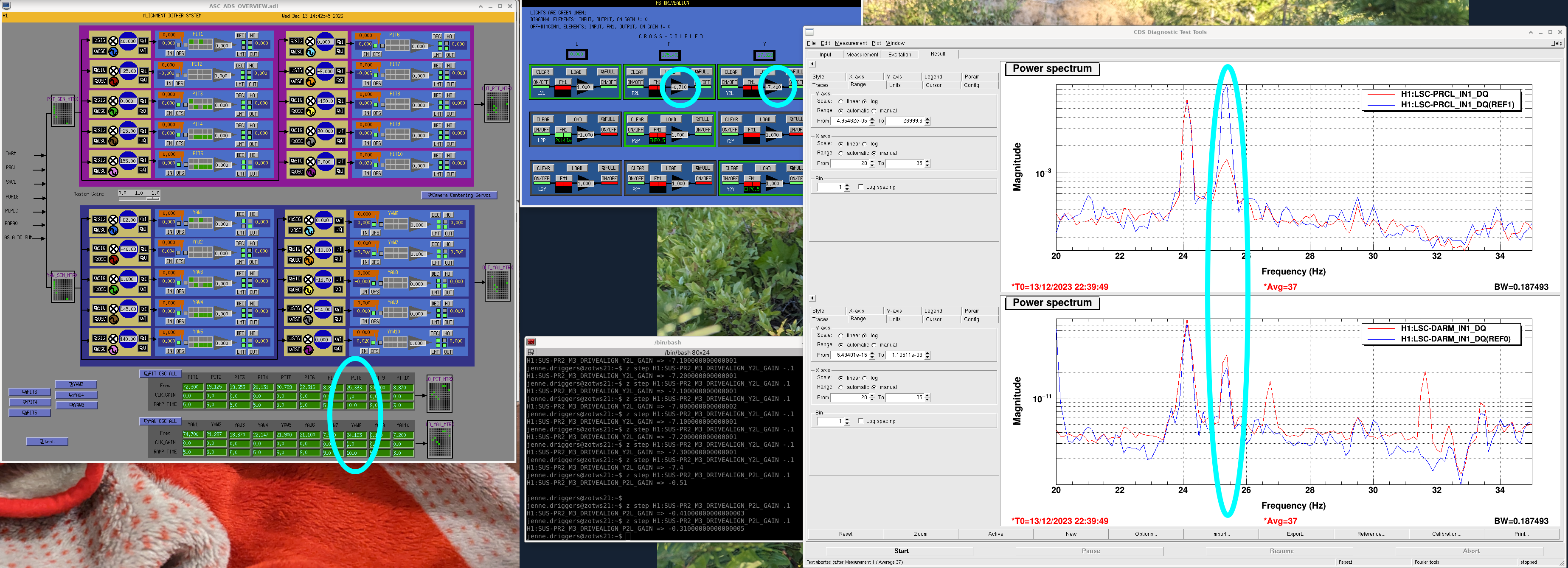
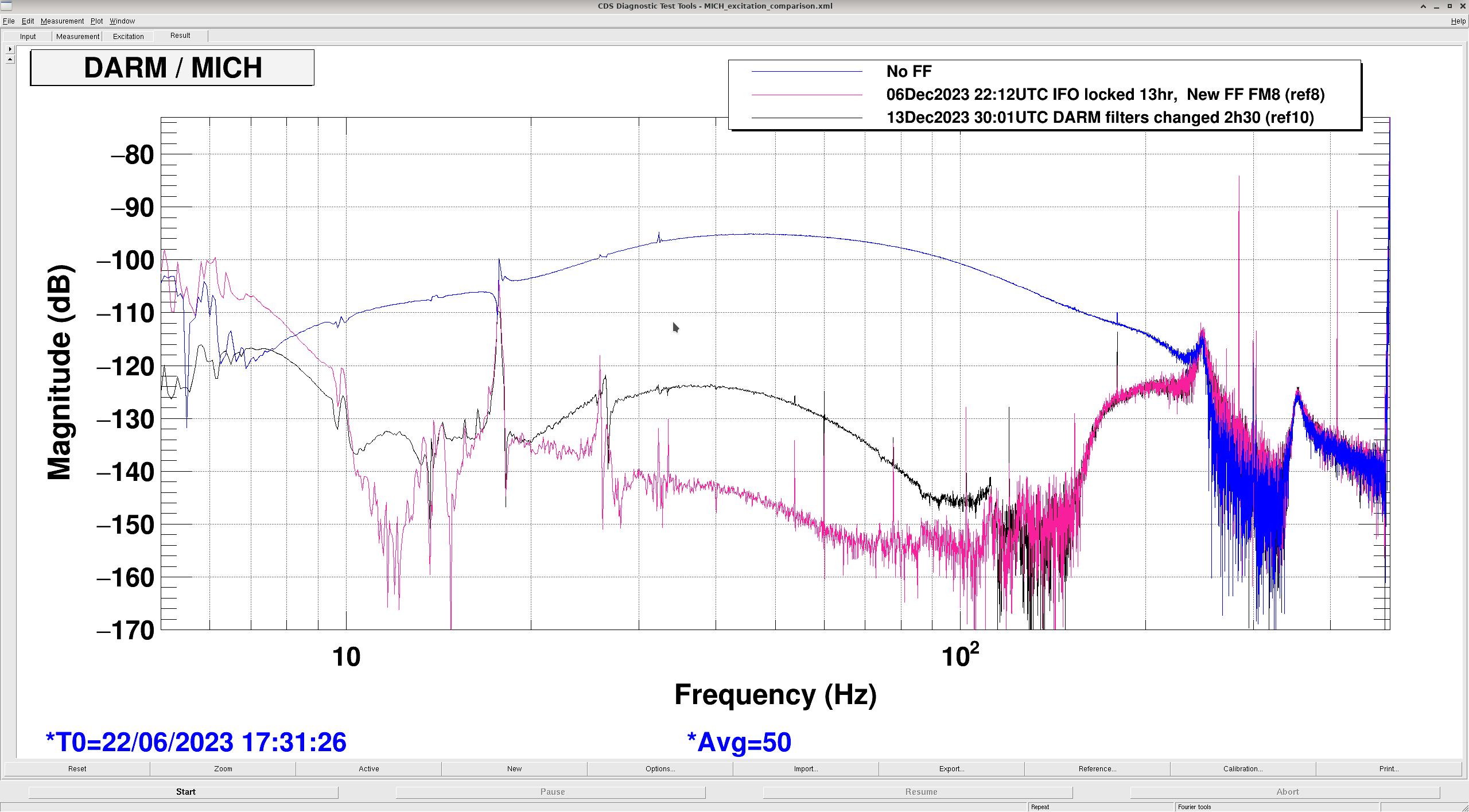
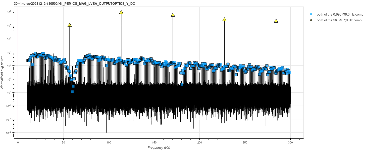
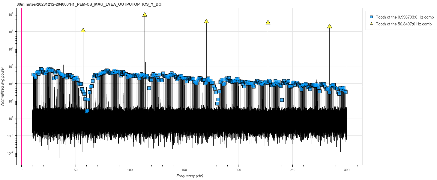
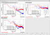
18 Hz – Beating shakers point to dominance of HAM2 MC baffle scattering at 18 Hz, velocity predicts scattering shelf edge, noise in DARM starts at about 5 times the 18 Hz vibration background: In order to determine if we should work on the baffle by HAM2 (strongest resonance at 18 Hz) in addition to the one by HAM3, I investigated whether the DARM noise from 18 Hz shaker injections was coming from the baffle at HAM2, or the one at HAM3, which also moves at 18 Hz during the injection. Figure 2 shows that both the beating shaker phase and the predicted shelf cut-off are consistent with coupling at the HAM2 MC baffle but not the HAM3 baffle. For my 18 Hz injection, the HAM2 MC baffle was moving about 230 microns per second, which predicts a scattering shelf cutoff of about 640 Hz, while the cutoff in DARM was at about 500 Hz, reasonable agreement. By slowly decreasing the shaking amplitude, I estimated that an increase in ambient at this frequency by about 5 would produce noise in DARM. There are many transients that can reach this level, and there may also be off-resonance coupling, so I think we should also work on the baffle by HAM2.
15.2 Hz – HAM2 and 3 MC baffles move about the same, was unable to determine which one dominates noise: The 15.2 Hz resonance is actually a beam-line resonance of the MC beam tube and so both baffles were moving about the same amount and I couldn’t distinguish between them by the shelf prediction. Unfortunately, I was also not able to distinguish between them with the beating shaker technique because my data were swamped by scattering from a 76 Hz resonance (the shaker was making higher harmonics). I was not able to eliminate this higher frequency shaking because one of the shakers broke down and I used a speaker as a shaker (which produced higher harmonics).
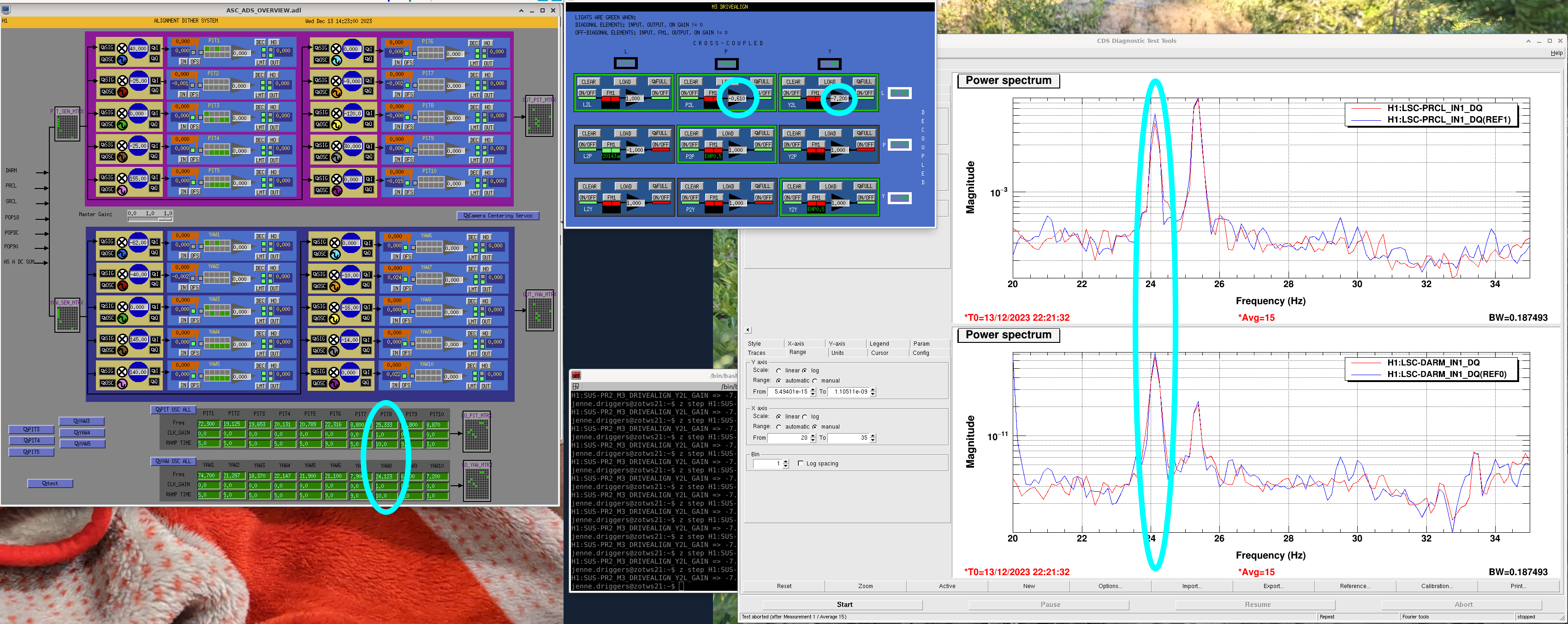
14.1 Hz – in between resonances, noise in DARM starts at about 3 times the 14.1 Hz vibration background: Figure 3 shows that noise starts appearing in DARM when vibration at 14.1 Hz is increased by about 3 over background. Since there is coupling over a 12-18 Hz band, a broad band increase of less than this would increase the velocity enough to show in DARM. As pointed out in (74175), this off-resonance coupling may be currently limiting DARM and be a source of broad-band HVAC coupling.
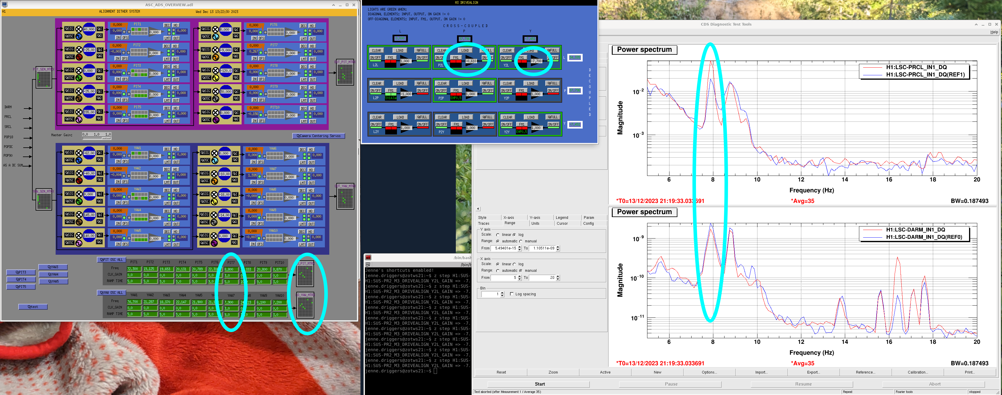
13.1 Hz – velocity of HAM3 MC baffle predicts DARM scattering shelf edge much better than velocity of HAM2 baffle – noise currently in DARM : The CER fans that cross 13.1 Hz increase motion of the MC tube by only a factor of 3 or so, strongly affecting DARM (73430), and my injections showed that at 13.1 Hz ambient noise levels may be limiting DARM at 13.1 Hz. For my larger injections, the vibrometer indicated that the sampled point on the baffle reached 120 um/s RMS, predicting a shelf cutoff of about 340 Hz, while the actual shelf cutoff was at about 450 Hz. So the part of the baffle doing the reflecting must be moving a little more than the point measured by the vibrometer. At 13.1 Hz, the motion of the MC baffle by HAM2 was more than an order of magnitude lower than the HAM3 baffle, excluding it.
When I return, it would be interesting to complement these single-frequeny injections with broader-band injections that could better determine the current contribution of ambient vibration to DARM.
Suggestions for mitigation
Figure 4 shows that the 5 degree angle of the baffles is small enough that some parts of the baffle are normal to scattered light from certain optics. The photographs in the figure, taken in 2017, show the retro-reflected light from the baffles at these optics. Betsy, Alena, Calum, Eddie, myself and others are working on the following mitigations:
1) Increase the angle of the baffles
2) Increase the damping of the baffles (Qs are now in the tens)
3) Attach small baffle panels to cover any remaining retro-reflective regions of the MC baffles
4) Reduce the buckling of the panels (74175), possibly by leaving out some bolts
5) We may eventually want to consider installing nozzle baffles where there are blanks, because of the 15 Hz resonance of the beam tube
ibrahim.abouelfettouh@LIGO.ORG - posted 08:17, Wednesday 13 December 2023 (74778)
OPS Day Shift Start
TITLE: 12/13 Day Shift: 16:00-00:00 UTC (08:00-16:00 PST), all times posted in UTC STATE of H1: Corrective Maintenance OUTGOING OPERATOR: TJ CURRENT ENVIRONMENT:
SEI_ENV state: CALM
Wind: 8mph Gusts, 6mph 5min avg
Primary useism: 0.02 μm/s
Secondary useism: 0.25 μm/s QUICK SUMMARY:
IFO is attempting to relock after ADC card failure in h1iopseib3. Erik, Richard and TJ worked on this about an hour before shift and got everything up and running again. See alog 74774 for details. EX seems misaligned (due to a trip) so may go through initial alignment if this lock attempt doesn't work.
Currently locking ALS though TJ mentioned lower ALSX/Y arm transmition than usual (by about 0.1/0.2 counts) - a weeklong issue apparently.
louis.dartez@LIGO.ORG - posted 01:05, Wednesday 13 December 2023 - last comment - 09:04, Wednesday 13 December 2023(74771)
Follow up to LHO DARM modeling efforts
Gabriele, Sheila, Artem, Louis
Since Gabriele found low frequency noise (~4 Hz) non-linearly coupling into DARM at higher frequencies (~15-25 Hz) (see LHO:73937), Sheila & I have been working to prop up a dependable model of the DARM loop that can be used to estimate stability margins and offload actuation from ETMX L3 to L2 and L1. N.B. we're not 100% certain that the noise we're chasing is due to the ETMX ESD.
1. The DARM Model
To estimate DARM loop stability, we've been primarily looking at modeling and directly measuring IN1/IN2 at the input to each stage's LOCK bank filter. IN1/IN2 at the input to the L3 LOCK bank filter (often measured as (IN1/EXC)/(IN2/EXC) so as to not be biased towards 1) is the open loop gain, G, of the DARM loop. We've been calling IN1/IN2 measured at the input to the L2 and L3 LOCK banks Gp and Gu, respectively. This is because they each behave somewhat like an effective open loop gain as measured at those points in the offloaded DARM loop. Similar to G, Gp, and Gu (the "OLGs"), we calculate the loop suppression, 1/(1-G), and the closed loop gain, G/(1-G), for each our three test points (G, Gp, and Gu) at the input of each ETMX LOCK bank filter.
Figure 1 above is a Bode plot of G, Gp, and Gu for the LHO DARM loop overlaid with measurements taken for G and Gu. The OLG, G, measurement was taken from a recent calibration swept sine and the measurement of Gu is courtesy of Sheila from LHO:74226. The two measurements shown for G and Gu match the model pretty well. There is some noise in the Gu measurement but the structure is in pretty good agreement between the model and the data. The measurement of G also matches pretty well but begins to deviate below 10 Hz. This is likely in large part due to error in fitting the sensing function, C, at low frequencies. It's worth noting that the UIM stage has multiple UGFs just below 2 Hz and 4 Hz; this is okay but not ideal.
We tried taking a measurement of Gp but we've been unable to get good agreement between the current DARM loop model and these measurements (this is mentioned in LHO:74264). We've only tried relatively low coherence measurements so far in this current sprint so we plan to get some better measurements of this soon to compare against the model. However, it's worth noting that the PUM has been a bear to model properly for a while (see for example the PUM discussion in LHO:63450). A few years ago Jenne successfully modeled length-to-pitch-to-length cross-coupling that matched data taken at the PUM stage (LHO:48738). In light of the recent modeling push, Sheila and I are have begun working to follow up on this work to include yaw in the hopes of modeling and suppressing this effect from coupling to DARM. More on that later as our current major goal is to reduce ETMX actuation as introduced at the top.
The Gu points in Figure 1 were calculated from a measurement of IN1/EXC at the input of the L2 stage LOCK bank filter. Direct measurement of Gu = IN1/IN2 was difficult due to low coherence. The relationship between Gu and IN1/IN2 is Gu = (IN1/EXC)/(1+(IN1/EXC)). See Section 4 of DCC:LIGO-T2300436 for a discussion on that relationship.
2. Comparison of LHO and LLO DARM Models
Here is a quick comparison of recent DARM loop models for LHO and LLO.
For searching purposes I'm writing their modeled OLG UGFs:
LHO UGFs:
1: 70.45 Hz, 26.97 degrees
LLO UGFs:
1: 78.75 Hz, 35.89 degrees
The DARM OLG magnitudes between LLO and LHO differ at low frequencies by roughly 3 orders of magnitude near 1Hz. Here's an even higher zoom near 1Hz: LHO_LLO_comparison_OLG_super_zoom_low_freq.png. As an independent check into whether that makes sense, Artem pulled up the external disturbance sent to each actuation stage at both sites using CAL-DELTAL_CTRL_{UIM,PUM,TST}_DBL_DQ and saw that they're similar between LLO and LHO (direct link to this plot). Then he looked at the LHO and LLO error signals and found a discrepancy of 2 orders of magnitude in the expected direction (direct link to this plot). So that all seems to roughly track, which is great news. See LHO:74744 for Artem's discussion.
3. Instability of 4.5Hz boost filter not predicted by DARM model
In LHO:74226, Sheila tried engaging a L2 LOCKL FM2, "boost4.5", which caused a lockloss. She successfully engaged the boost without a lockloss the day before just before the Tuesday maintenance period.
Here is a comparison of the LHO model with and without this boost engaged.
The hope was that we would look at the model with the boost included and be able to confirm that the resultant loop configuration is unstable. However, we aren't able to point to anything that obviously indicates that that's the case. The corresponding loop suppression plot shows some peaking near 10Hz but nothing that would have us consider it a smoking gun.
=====
So the DARM modeling efforts are progressing but there is still much to do..
Images attached to this report
Comments related to this report
louis.dartez@LIGO.ORG - 09:04, Wednesday 13 December 2023 (74780)
after discussing a bit with Gabriele this morning and taking a closer look at the scenario with the 4.5Hz boost applied, I think I was too quick to suggest that the instability disagrees with the model.
1. There is some minor gain peaking the TST stage near 10Hz with the boost applied compared to the nominal state.
2. Gp inches closer to unity at 10Hz. Given that we already don't trust the Gp model right now, this could put us close enough to unity to cause issues at 10Hz, which is also where the phase goes to 0.
3. OLG also starts to dip to unity near 10Hz.
all this together may actually suggest that the loop with the 4.5Hz boost engaged, or the transition from the nominal state to the new state with the boost engaged, could be unstable. So perhaps Sheila's experience with having the boost be fine one day and cause a lockloss the next day is consistent with the model afterall.
david.barker@LIGO.ORG - posted 11:01, Tuesday 12 December 2023 - last comment - 13:17, Wednesday 13 December 2023(74755)
WP11568 TW0 raw minute trends offload
As the first part of the TW0 raw minute trend file offload, tw0 is now writing to a new area freeing up the old files for transfer.
nds0 was restarted at 10:44 PST to serve the past 6 months of data from their temporary location as the files are being transferred to h1daqframes-0. The file copy takes about 30 hours.
Comments related to this report
david.barker@LIGO.ORG - 16:22, Tuesday 12 December 2023 (74769)
camilla.compton@LIGO.ORG - posted 08:26, Tuesday 12 December 2023 - last comment - 13:12, Wednesday 13 December 2023(74750)
ITM HWS Camera's Powered off at 16:15UTC, search for cause of DARM Comb
This morning at 8:15am (16:15UTC) I turned off the external power supply that powered both ITM HWS CCD cameras (Dalsa 1M60), located on the floor under the HWS table. We'll plan to check the magnetometer data to see if the 74738 comb is still present.
After we stopped HWS code and remotely turned off camera's in 74738, the DARM comb still remained. Dan, Daniel, Nutsinee expect this could be the framegrabber in the HWS computer still sending a 7Hz signal. We can troubleshoot this and how the camera's are grounded to the optics table later.
Comments related to this report
ansel.neunzert@LIGO.ORG - 09:29, Tuesday 12 December 2023 (74752)
Camilla says the camera was turned on but not initialized at 10:03 Pacific / 18:03 UTC. Took a 30m spectrum starting 18:05 utc, attached. There is a strong near-1Hz comb and a strong near-57 Hz comb.
Images attached to this comment
camilla.compton@LIGO.ORG - 12:44, Tuesday 12 December 2023 (74759)
At 20:40UTC (12:40PT) we powered off both ITM computers h1hwsmsr and h1hwsmsr1. Dave has been notified. In 30 minutes we can try power cycling the cameras to see if the computers are off whether they re-initalize causing a comb.
ansel.neunzert@LIGO.ORG - 13:34, Tuesday 12 December 2023 (74762)
Combs are still there with ITM computers off. Looks pretty much identical to the previous spectrum (very tiny frequency shift in the near-1Hz comb, though).
Images attached to this comment
camilla.compton@LIGO.ORG - 13:44, Tuesday 12 December 2023 (74764)
At 21:30UTC Erik unplugged the fiber connections that run from the back of the computers to the HWS cameras. Computers still off.
At 21:37UTC I power cycled the external supply to the cameras, to test if the cameras still turn on with a comb with no computer/frame grabber connection.
camilla.compton@LIGO.ORG - 16:37, Tuesday 12 December 2023 (74770)
When the camera's restanted with the fiber link to the computers disconneted, we again saw the 1Hz and 57Hz combs, plot attached. It appears default for ITMX is 57Hz and ITMY is 1Hz. We should check if the camera software allows us to to put these to zero/ off.
For now we've replugged in the fiber connections, turned on the computers and restarted the hws code, both at 7Hz (this created some sdf diffs from the H1:TCS-ITMY_HWS_{}_POS_{X,Y} channels restarting with default values that kicked us out of observing, sorry)
Lasers still off, will turn lasers on tomorrow during commissioning to avoid sdf diffs.
Images attached to this comment
camilla.compton@LIGO.ORG - 13:12, Wednesday 13 December 2023 (74785)
sheila.dwyer@LIGO.ORG - posted 15:44, Wednesday 15 November 2023 - last comment - 12:11, Friday 15 December 2023(74226)
DARM offloading
Louis and I have been looking at increasing the offloading of the signal from the ESD to the PUM and UIM, in light of 73913.
I have attempted a few times to make measurements by exciting at the L2 LOCK L filter, this results in poor coherence even for amplitudes that are quite large in DARM, and turning up the amplitude slightly has caused a lockloss by saturating the ESD.
On Tuesday morning I engaged the PUM boost (L2 LOCKL FM2, boost4.5 which is a boost with a little resG aaround 4.5Hz). Some history (with links to old alogs about this filter is here: 48767) we used to run with this boost but turned it off in early O3 because angle to length cross couplings were causing instabilities of the DARM loop. On Tuesday morning I engaged this boost, and we stayed locked. The first attachment shows a comparison of our ETMX drives to LLO's (LLO also uses ETMY L1 for DARM control, but I haven't plotted that here), H1's usual configuration is in gold and the time with the PUM boost engaged is in red. The ESD drive RMS is reduced by more than a fator of 2 with the PUM boost engaged. I quickly tried a swept sine injection, and saw that the coherence was somewhat better than earlier measurements with a very small amplitude injection, so it seemed promising that we might be able to get a better measurement of the cross over with the PUM boost engaged.
Today I engaged this boost again during commisoning time and we immediately lost lock. The third attachment shows that turning on the boost certainly seems to be the cause of the lockloss.
We can probably rely on the pyDARM model for the PUM crossover, since the calibration measurements validate the model above 10Hz. Today I was able to make a measurement of the UIM crossover, which Louis can use to compare to pyDARM from 1-10Hz.
Gabriele, Louis
The comparison between LLO's and LHO's ETMX L3 drive above (fist attachment in Sheila's post) confused us. The difference between the two LHO traces makes sense. But there are several things wrong with the channel from LLO (blue trace in top right hand plot). First of all, we do not have 2 orders of magnitude in difference between the L3 MASTER OUT drives at LLO vs LHO. Also, the calibration lines show up at the wrong frequencies in the LLO trace.
It turns out that if you use NDS2 and leave the Epoch Start date at the default 6/1/1980, DTT sees two of some channels with the same name (but different sampling frequencies!), see DTT_NDS_issue.png.
The result in this case was confusion of what DTT was plotting in Sheila's alog. We think that DTT got confused by having multiple channels with the same name but differing sampling frequencies in its lookup list, leading to DTT plotting the 16kHz channel but somehow applying the wrong sampling frequency.
To avoid this, we had to re-remember to be careful when copying and pasting similar channel names from one text box to another within DTT and to set the Epoch Start field to something more reasonable than 1980.