X End Station Measurement:
During the Tuesday maintenace, the PCAL team(Rick Savage, Dana Jones, & Tony Sanchez) went to EndX with Working Standard Hanford aka WSH(PS4) and took an End station measurements.
The EndX Station Measurements were carried out according to the procedure outlined in Document LIGO-T1500062-v15, Pcal End Station Power Sensor Responsivity Ratio Measurements: Procedures and Log, and was completed by 11:45 am.
Note:
After the normal measurement, we did a few auxilary measurments.
LIGO-T1500062-v15 Measurement Log
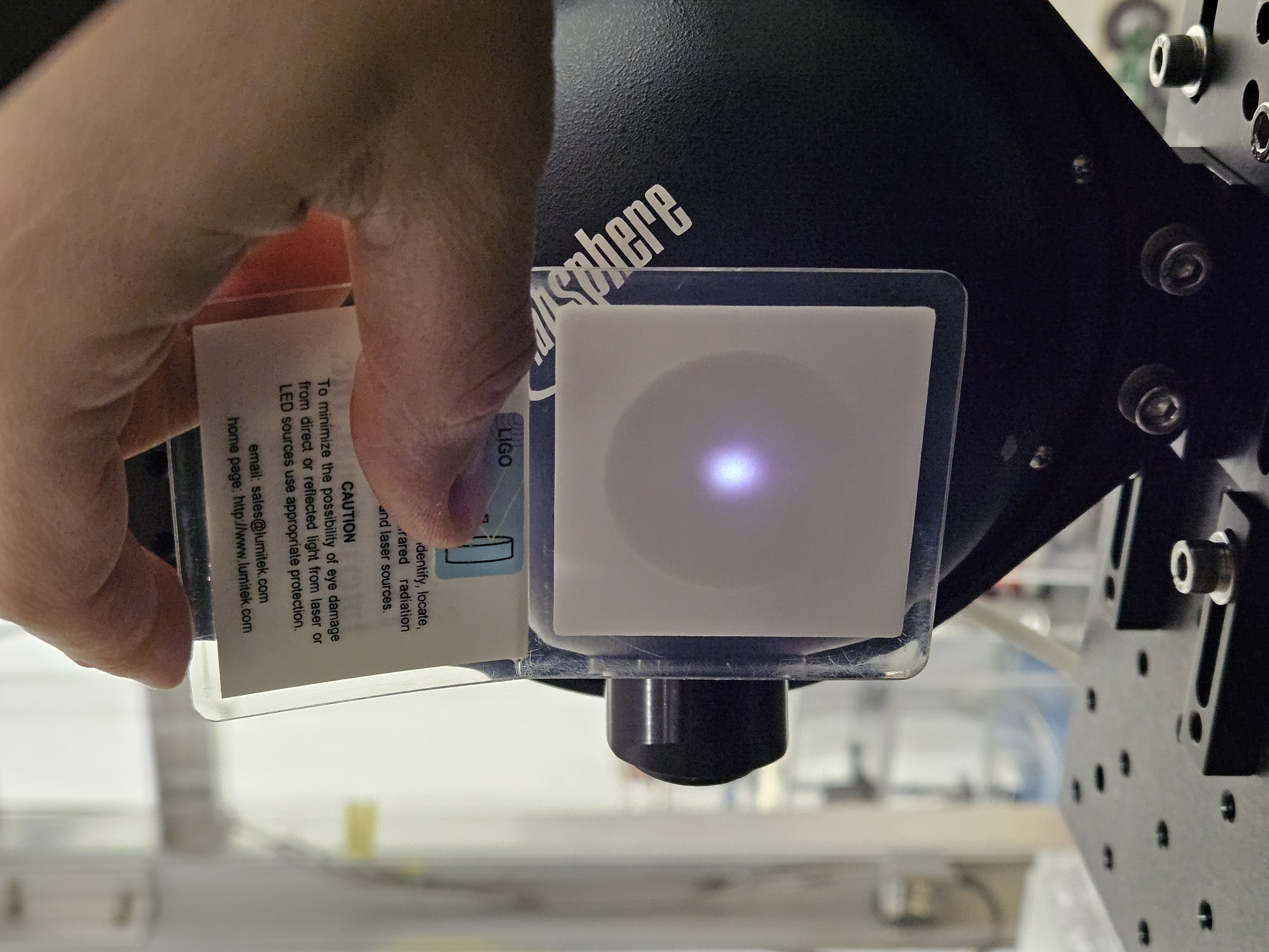
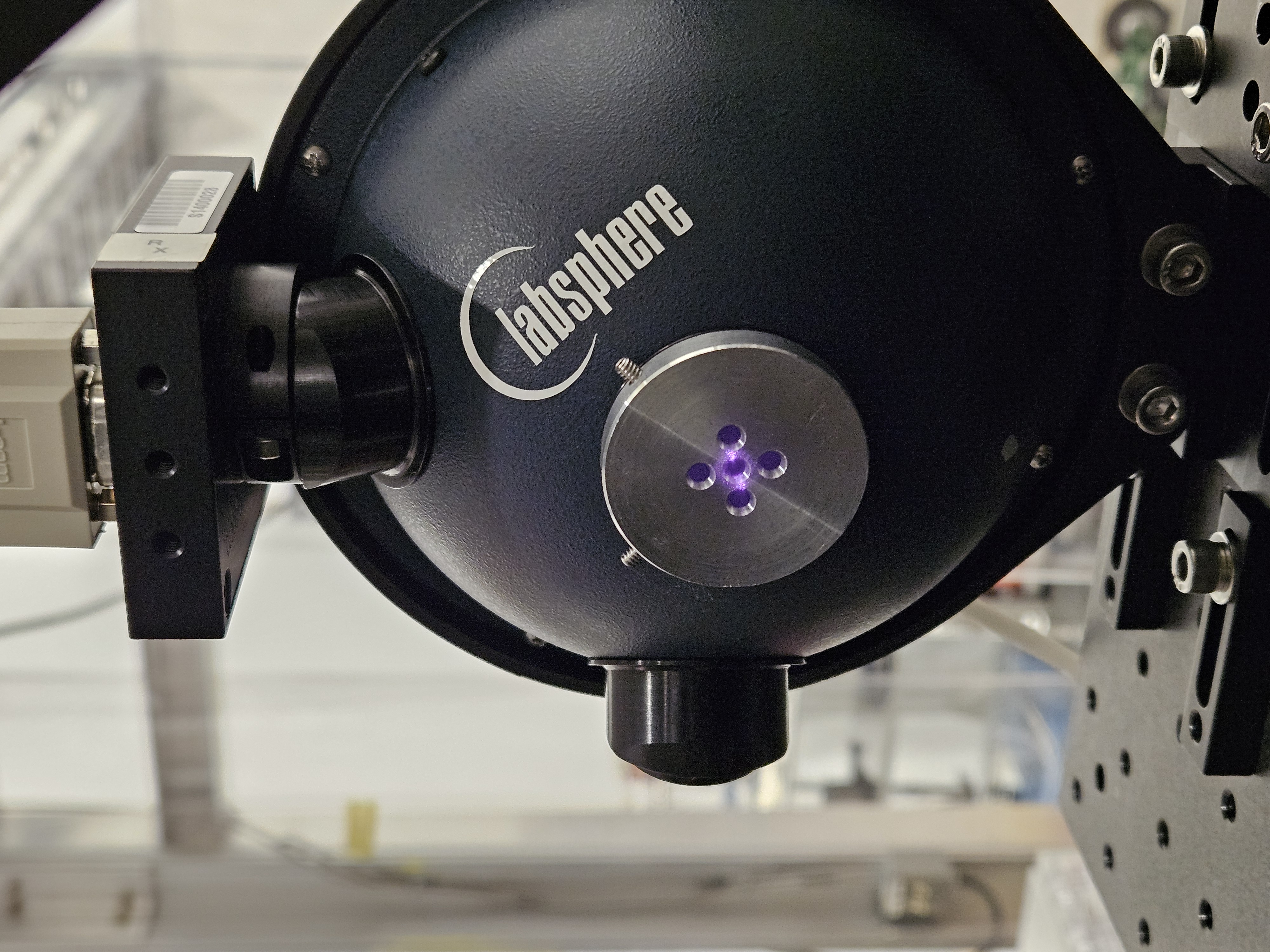
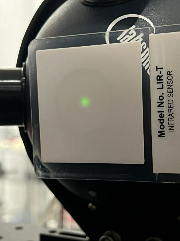
First thing we did is take a picture of the beam spot before anything is touched! I then put the target apature cap on the RX sphere to see how far off from center the beam is.
Martel:
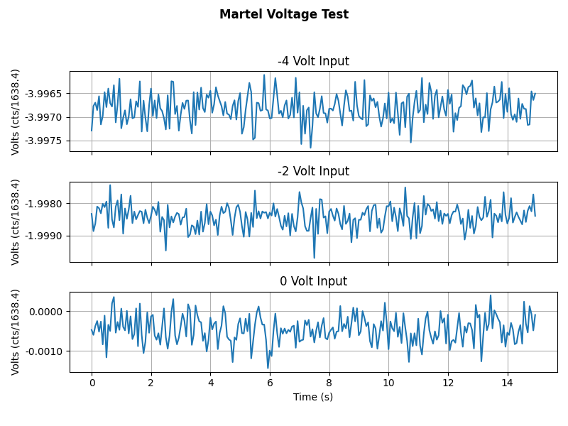
Martel Voltage sources voltage into the PCAL Chassis's Input 1 channel. We record the GPStimes that a -4.000V, -2.000V and a 0.000V voltage was applied to the Channel. This can be seen in Martel_Voltage_Test.png. We also did a measurement of the Martel's voltages in the PCAL lab to calculate the ADC conversion factor, which is included on the above document.
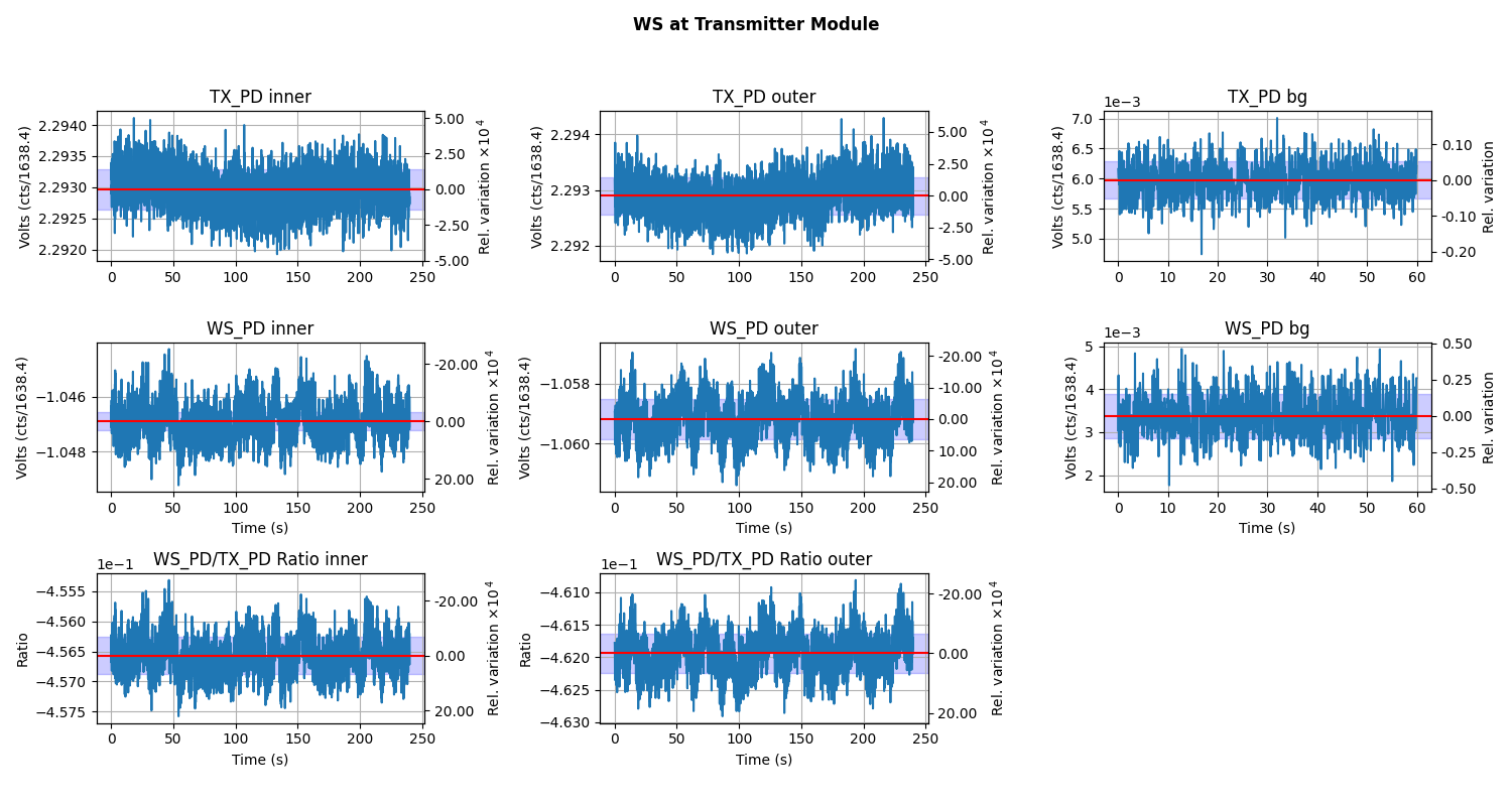
Plots while the Working Standard(PS4) is in the Transmitter Module during Inner beam being blocked, then the outer beam being block, followed by the background measurment: WS_at_TX.png.
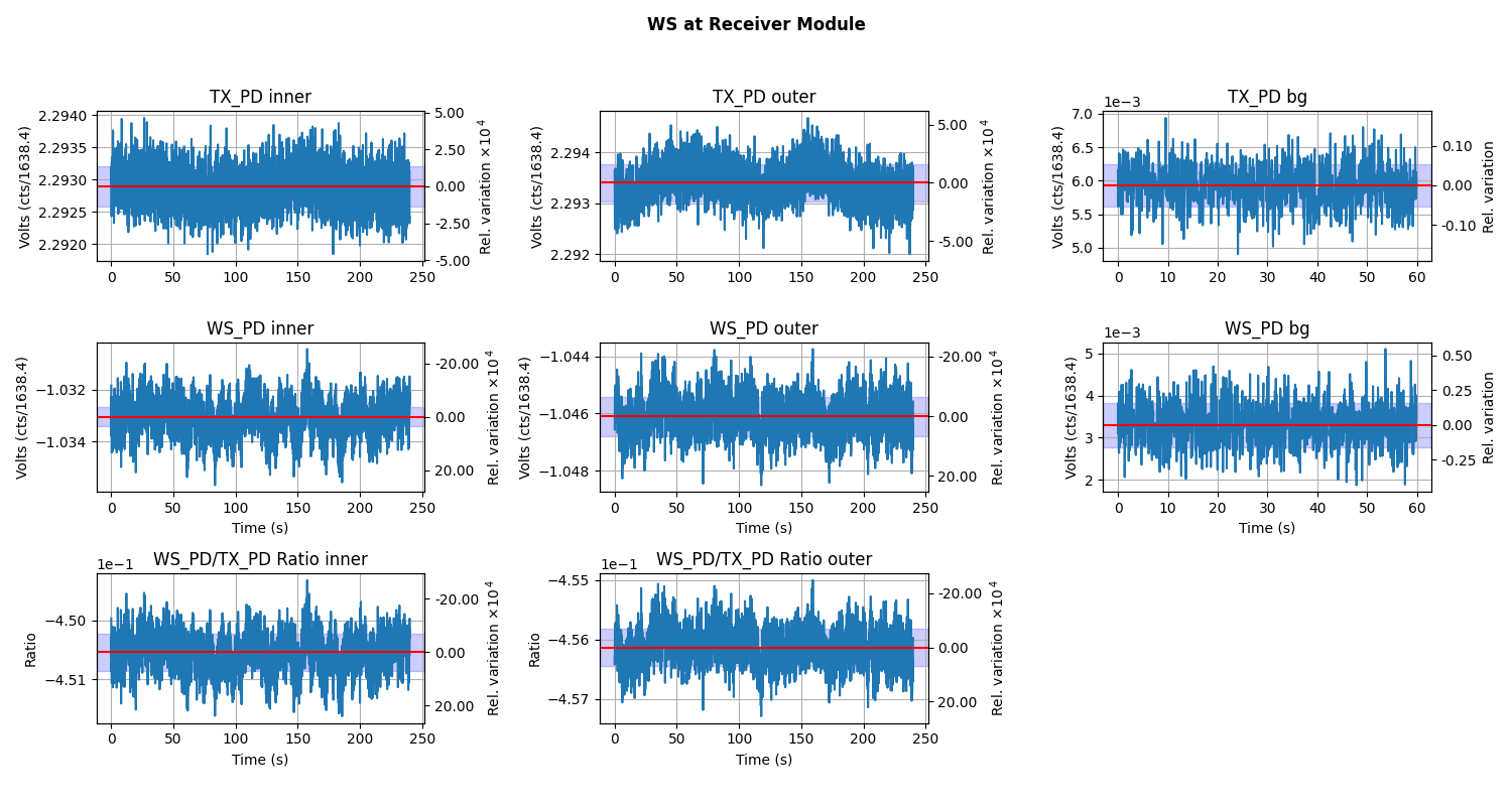
The Inner, outer, and background measurement while WS in the Receiver Module: WS_at_RX.png.
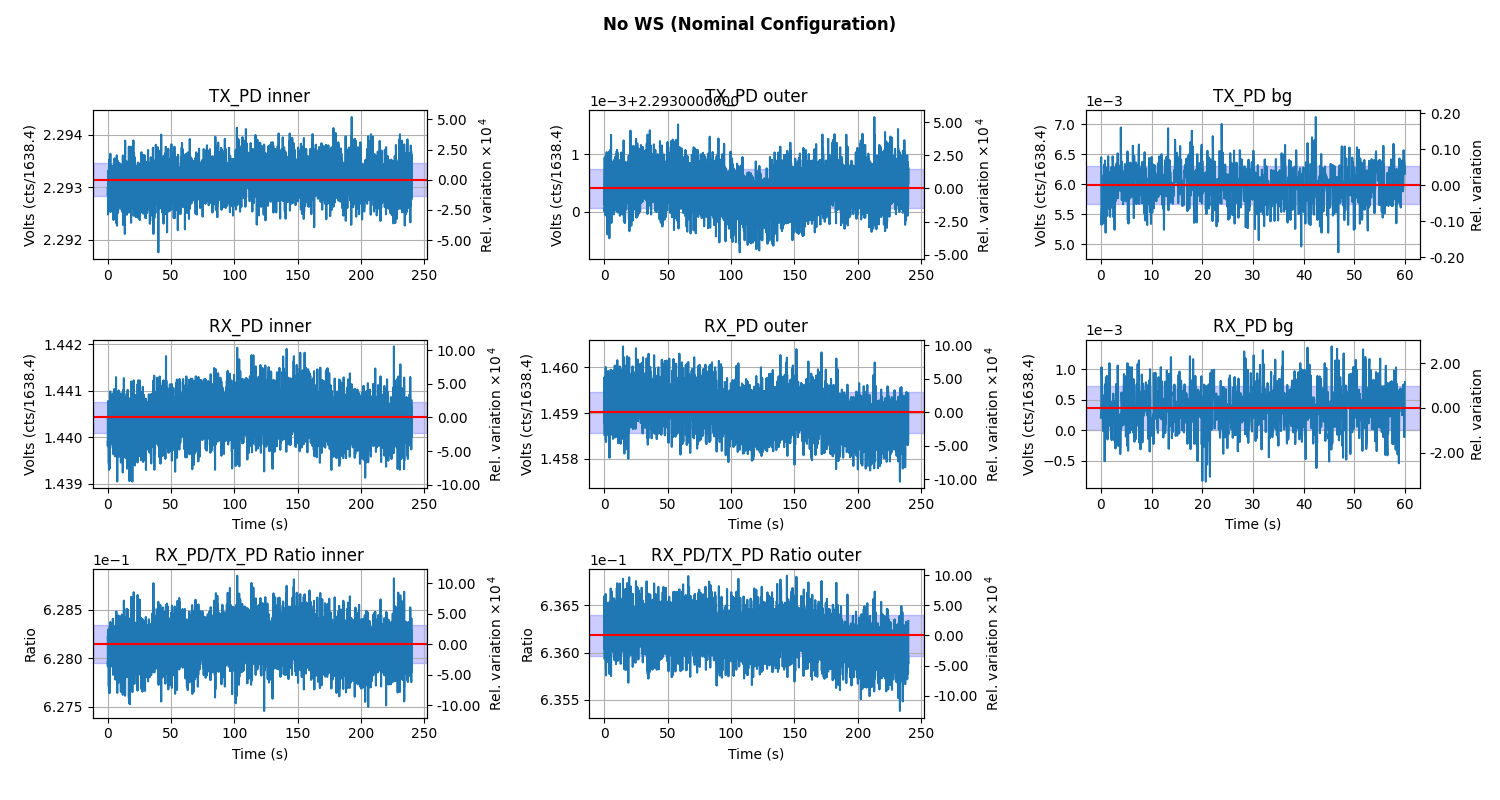
The Inner, outer, and background measurement while RX Sphere is in the RX enclosure, which is our nominal set up without the WS in the beam path at all.: TX_RX.png.
The last picture is of the Beam spot after we had finished the measurement. Note this beam spot is only ONE beam but the beam postitons were not adjusted during the measurement.
All of this data is then used to generate LHO_EndX_PD_ReportV2.pdf which is attached, and a work in progress in the form of a living document. This document was created with the PCALPARAMS['WHG'] = 0.916985 # PS4_PS5 as of 2023/04/18
And Not the latest number [PCALPARAMS['WHG'] = 0.91536 # 12/05/2023].
But I did run the report with the latest number just for my own curiosity and marked it down as a "Monday End Station measurement" performed on 2023-12-04 so it sits right behind the real measurement on the 5th and it doesn't vary by much: LHO_ENDX_PD_TEST_REPORT.pdf
All of this data and Analysis has been commited to the SVN :
https://svn.ligo.caltech.edu/svn/aligocalibration/trunk/Projects/PhotonCalibrator/measurements/LHO_EndX/
This is where the measurement normally ends, but instead we took a few more iteresting measurements.
Auxilary Measurements:
Rx Sphere is in it's nominal location and the WS was not in the beam path at all.
Opened the Shutter GPStime 1385839530
RxPD = 0.2234 before moving the beam block.
Moved the beam block allowing both beams to hit RX sphere.
start time 1385839590
End time 1385839890
Shutter both beams for a background measurement.
Start time 1385839945
RxPD = 4.30966e-5
End time 1385840005
The OFSPD_OFFSET was set to 6.0. This should be the maximum power we reach while normally operating.
start time 1385840225
RXPD = 0.805388
TXPD = 0.813297
End time 1385840525
PCAL Lab Responsivity Ratio Measurement:
A WSH/GSHL (PS4/PS5)FrontBack Responsivity Ratio Measurement was ran, analyzed, and pushed to the SVN.
The analysis of this measurement produces 4 PDF files which we use to vet the data for problems.
raw_voltages.pdf
avg_voltages.pdf
raw_ratios.pdf
avg_ratios.pdf
Obligitory BackFront PS4/PS5 Responsivity Ratio:
A WSH/GSHL (PS4/PS5)BF Responsivity Ratio measurement was ran, analyzed, and pushed to the SVN.
The analysis of this measurement produces 4 PDF files which we use to vet the data for problems.
raw_voltages2.pdf
avg_voltages2.pdf
raw_ratios2.pdf
avg_ratios2.pdf
This adventure has been brought to you by Rick Savage, Dana Jones & Tony Sanchez.