Famis 25079
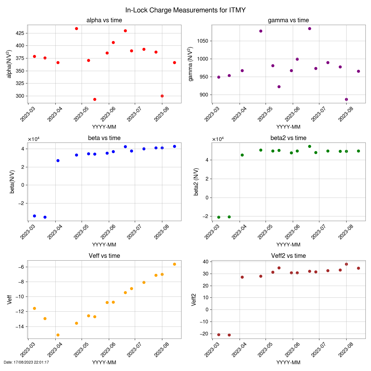
inLock SUS Charge Measurement
While searching for the files created by the inLock Sus Charge Measurments.
I noticed that there were multiples of a few of the files created today in the directory: /opt/rtcds/userapps/release/sus/common/scripts/quad/InLockChargeMeasurements/rec_LHO
ls -l | grep "Aug 15"
-rw-r--r-- 1 1010 controls 160 Aug 15 07:50 ETMY_12_Hz_1376146243.txt
-rw-r--r-- 1 1010 controls 160 Aug 15 08:22 ETMY_12_Hz_1376148152.txt
-rw-r--r-- 1 1010 controls 160 Aug 15 07:50 ITMX_14_Hz_1376146241.txt
-rw-r--r-- 1 1010 controls 160 Aug 15 08:22 ITMX_14_Hz_1376148154.txt
-rw-r--r-- 1 1010 controls 160 Aug 15 07:50 ITMY_15_Hz_1376146220.txt
-rw-r--r-- 1 1010 controls 160 Aug 15 08:08 ITMY_15_Hz_1376147322.txt
-rw-r--r-- 1 1010 controls 160 Aug 15 08:21 ITMY_15_Hz_1376148134.txt
listing all files, filtering for only files that contain the string ETMX, and then filtering those for files that contain "Aug 15" with the following command:
ls -l | grep "ETMX" | grep "Aug 15"
Returned no files, which means that while it looks like it was ran twice, it never completed ETMX.
I'm not sure if the analysis will run with out all the files or not.
SUS_CHARGE LOG:
2023-08-15_15:26:18.969345Z SUS_CHARGE LOAD ERROR: see log for more info (LOAD to reset)
2023-08-15_15:26:53.512031Z SUS_CHARGE LOAD REQUEST
2023-08-15_15:26:53.524359Z SUS_CHARGE RELOAD requested. reloading system data...
2023-08-15_15:26:53.527151Z SUS_CHARGE Traceback (most recent call last):
2023-08-15_15:26:53.527151Z File "/usr/lib/python3/dist-packages/guardian/daemon.py", line 566, in run
2023-08-15_15:26:53.527151Z self.reload_system()
2023-08-15_15:26:53.527151Z File "/usr/lib/python3/dist-packages/guardian/daemon.py", line 327, in reload_system
2023-08-15_15:26:53.527151Z self.system.load()
2023-08-15_15:26:53.527151Z File "/usr/lib/python3/dist-packages/guardian/system.py", line 400, in load
2023-08-15_15:26:53.527151Z module = self._load_module()
2023-08-15_15:26:53.527151Z File "/usr/lib/python3/dist-packages/guardian/system.py", line 287, in _load_module
2023-08-15_15:26:53.527151Z self._module = self._import(self._modname)
2023-08-15_15:26:53.527151Z File "/usr/lib/python3/dist-packages/guardian/system.py", line 159, in _import
2023-08-15_15:26:53.527151Z module = _builtin__import__(name, *args, **kwargs)
2023-08-15_15:26:53.527151Z File "<frozen importlib._bootstrap>", line 1109, in __import__
2023-08-15_15:26:53.527151Z File "<frozen importlib._bootstrap>", line 1030, in _gcd_import
2023-08-15_15:26:53.527151Z File "<frozen importlib._bootstrap>", line 1007, in _find_and_load
2023-08-15_15:26:53.527151Z File "<frozen importlib._bootstrap>", line 986, in _find_and_load_unlocked
2023-08-15_15:26:53.527151Z File "<frozen importlib._bootstrap>", line 680, in _load_unlocked
2023-08-15_15:26:53.527151Z File "<frozen importlib._bootstrap_external>", line 786, in exec_module
2023-08-15_15:26:53.527151Z File "<frozen importlib._bootstrap_external>", line 923, in get_code
2023-08-15_15:26:53.527151Z File "<frozen importlib._bootstrap_external>", line 853, in source_to_code
2023-08-15_15:26:53.527151Z File "<frozen importlib._bootstrap>", line 228, in _call_with_frames_removed
2023-08-15_15:26:53.527151Z File "/opt/rtcds/userapps/release/sus/h1/guardian/SUS_CHARGE.py", line 67
2023-08-15_15:26:53.527151Z ezca.get_LIGOFilter('SUS-ETMX_L3_DRIVEALIGN_L2L').ramp_gain(lscparams.ETMX_GND_MIN_DriveAlign_gain, ramp_time=20, wait=False)
2023-08-15_15:26:53.527151Z ^
2023-08-15_15:26:53.527151Z IndentationError: unindent does not match any outer indentation level
2023-08-15_15:26:53.527151Z SUS_CHARGE LOAD ERROR: see log for more info (LOAD to reset)
2023-08-15_15:29:10.009828Z SUS_CHARGE LOAD REQUEST
2023-08-15_15:29:10.011001Z SUS_CHARGE RELOAD requested. reloading system data...
2023-08-15_15:29:10.050137Z SUS_CHARGE module path: /opt/rtcds/userapps/release/sus/h1/guardian/SUS_CHARGE.py
2023-08-15_15:29:10.050393Z SUS_CHARGE user code: /opt/rtcds/userapps/release/isc/h1/guardian/lscparams.py
2023-08-15_15:29:10.286761Z SUS_CHARGE system archive: code changes detected and committed
2023-08-15_15:29:10.331427Z SUS_CHARGE system archive: id: 9b481a54e45bfda96fa2f39f98978d76aa6ec7c0 (162824613)
2023-08-15_15:29:10.331427Z SUS_CHARGE RELOAD complete
2023-08-15_15:29:10.332868Z SUS_CHARGE calculating path: SWAP_TO_ITMX->INJECTIONS_COMPLETE
2023-08-15_15:29:14.129521Z SUS_CHARGE OP: EXEC
2023-08-15_15:29:14.129521Z SUS_CHARGE executing state: SWAP_TO_ITMX (11)
2023-08-15_15:29:14.135913Z SUS_CHARGE W: RELOADING @ SWAP_TO_ITMX.main
2023-08-15_15:29:14.158532Z SUS_CHARGE [SWAP_TO_ITMX.enter]
2023-08-15_15:29:14.276536Z SUS_CHARGE [SWAP_TO_ITMX.main] ezca: H1:SUS-ITMX_L3_DRIVEALIGN_L2L_TRAMP => 10
2023-08-15_15:29:14.277081Z SUS_CHARGE [SWAP_TO_ITMX.main] ezca: H1:SUS-ITMX_L3_DRIVEALIGN_L2L_GAIN => 0
2023-08-15_15:29:17.820392Z SUS_CHARGE REQUEST: DOWN
2023-08-15_15:29:17.821281Z SUS_CHARGE calculating path: SWAP_TO_ITMX->DOWN
2023-08-15_15:29:17.822235Z SUS_CHARGE new target: DOWN
2023-08-15_15:29:17.822364Z SUS_CHARGE GOTO REDIRECT
2023-08-15_15:29:17.822669Z SUS_CHARGE REDIRECT requested, timeout in 1.000 seconds
2023-08-15_15:29:17.824392Z SUS_CHARGE REDIRECT wait for worker completion...
2023-08-15_15:29:17.895303Z SUS_CHARGE REDIRECT wait for worker completion...
2023-08-15_15:29:17.958976Z SUS_CHARGE REDIRECT wait for worker completion...
2023-08-15_15:29:18.018262Z SUS_CHARGE REDIRECT wait for worker completion...
2023-08-15_15:29:18.079443Z SUS_CHARGE REDIRECT wait for worker completion...
2023-08-15_15:29:18.130595Z SUS_CHARGE REDIRECT wait for worker completion...
2023-08-15_15:29:18.197848Z SUS_CHARGE REDIRECT wait for worker completion...
2023-08-15_15:29:18.253456Z SUS_CHARGE REDIRECT wait for worker completion...
2023-08-15_15:29:18.318549Z SUS_CHARGE REDIRECT wait for worker completion...
2023-08-15_15:29:18.378993Z SUS_CHARGE REDIRECT wait for worker completion...
2023-08-15_15:29:18.446375Z SUS_CHARGE REDIRECT wait for worker completion...
2023-08-15_15:29:18.507978Z SUS_CHARGE REDIRECT wait for worker completion...
2023-08-15_15:29:18.576823Z SUS_CHARGE REDIRECT wait for worker completion...
2023-08-15_15:29:18.641493Z SUS_CHARGE REDIRECT wait for worker completion...
2023-08-15_15:29:18.695114Z SUS_CHARGE REDIRECT wait for worker completion...
2023-08-15_15:29:18.774571Z SUS_CHARGE REDIRECT wait for worker completion...
2023-08-15_15:29:18.822999Z SUS_CHARGE REDIRECT wait for worker completion...
2023-08-15_15:29:18.823662Z SUS_CHARGE REDIRECT timeout reached. worker terminate and reset...
2023-08-15_15:29:18.831141Z SUS_CHARGE worker terminated
2023-08-15_15:29:18.849938Z SUS_CHARGE W: initialized
2023-08-15_15:29:18.871834Z SUS_CHARGE W: EZCA v1.4.0
2023-08-15_15:29:18.872835Z SUS_CHARGE W: EZCA CA prefix: H1:
2023-08-15_15:29:18.872835Z SUS_CHARGE W: ready
2023-08-15_15:29:18.872980Z SUS_CHARGE worker ready
2023-08-15_15:29:18.883790Z SUS_CHARGE EDGE: SWAP_TO_ITMX->DOWN
2023-08-15_15:29:18.884081Z SUS_CHARGE calculating path: DOWN->DOWN
2023-08-15_15:29:18.886386Z SUS_CHARGE executing state: DOWN (2)
2023-08-15_15:29:18.891745Z SUS_CHARGE [DOWN.enter]
2023-08-15_15:29:18.893116Z Warning: Duplicate EPICS CA Address list entry "10.101.0.255:5064" discarded
2023-08-15_15:29:20.216958Z SUS_CHARGE [DOWN.main] All nodes taken to DOWN, ISC_LOCK should have taken care of reverting settings.
ESD_EXC_ETMX LOG:
2023-08-01_15:07:01.324869Z ESD_EXC_ETMX REQUEST: DOWN
2023-08-01_15:07:01.325477Z ESD_EXC_ETMX calculating path: DOWN->DOWN
2023-08-15_15:02:53.269349Z ESD_EXC_ETMX REQUEST: DOWN
2023-08-15_15:02:53.269349Z ESD_EXC_ETMX calculating path: DOWN->DOWN
2023-08-15_15:08:26.888655Z ESD_EXC_ETMX REQUEST: DOWN
2023-08-15_15:08:26.888655Z ESD_EXC_ETMX calculating path: DOWN->DOWN
2023-08-15_15:29:20.255431Z ESD_EXC_ETMX REQUEST: DOWN
2023-08-15_15:29:20.255431Z ESD_EXC_ETMX calculating path: DOWN->DOWN
ESD_EXC_ITMX log:
2023-08-15_15:22:16.033411Z ESD_EXC_ITMX [RESTORE_SETTINGS.main] Restoring things to the way they were before the measurement
2023-08-15_15:22:16.033411Z ESD_EXC_ITMX [RESTORE_SETTINGS.main] Ramping on bias on ITMX ESD
2023-08-15_15:22:16.034430Z ESD_EXC_ITMX [RESTORE_SETTINGS.main] ezca: H1:SUS-ITMX_L3_LOCK_BIAS_GAIN => 0
2023-08-15_15:22:18.266457Z ESD_EXC_ITMX [RESTORE_SETTINGS.main] ezca: H1:SUS-ITMX_L3_LOCK_BIAS_SW1 => 8
2023-08-15_15:22:18.517569Z ESD_EXC_ITMX [RESTORE_SETTINGS.main] ezca: H1:SUS-ITMX_L3_LOCK_BIAS => OFF: OFFSET
2023-08-15_15:22:18.518166Z ESD_EXC_ITMX [RESTORE_SETTINGS.main] ezca: H1:SUS-ITMX_L3_LOCK_BIAS_TRAMP => 20
2023-08-15_15:22:18.518777Z ESD_EXC_ITMX [RESTORE_SETTINGS.main] ezca: H1:SUS-ITMX_L3_LOCK_BIAS_GAIN => 1.0
2023-08-15_15:22:38.431399Z ESD_EXC_ITMX [RESTORE_SETTINGS.main] ezca: H1:SUS-ITMX_L3_LOCK_BIAS_TRAMP => 2.0
2023-08-15_15:22:41.264244Z ESD_EXC_ITMX [RESTORE_SETTINGS.main] ezca: H1:SUS-ITMX_L3_DRIVEALIGN_L2L_SW1S => 5124
2023-08-15_15:22:41.515470Z ESD_EXC_ITMX [RESTORE_SETTINGS.main] ezca: H1:SUS-ITMX_L3_DRIVEALIGN_L2L => ONLY ON: INPUT, DECIMATION, FM4, FM5, OUTPUT
2023-08-15_15:22:41.515470Z ESD_EXC_ITMX [RESTORE_SETTINGS.main] all done
2023-08-15_15:22:41.632738Z ESD_EXC_ITMX EDGE: RESTORE_SETTINGS->COMPLETE
2023-08-15_15:22:41.632738Z ESD_EXC_ITMX calculating path: COMPLETE->COMPLETE
2023-08-15_15:22:41.632738Z ESD_EXC_ITMX executing state: COMPLETE (30)
2023-08-15_15:22:41.636417Z ESD_EXC_ITMX [COMPLETE.enter]
2023-08-15_15:22:41.764636Z ESD_EXC_ITMX REQUEST: DOWN
2023-08-15_15:22:41.764636Z ESD_EXC_ITMX calculating path: COMPLETE->DOWN
2023-08-15_15:22:41.764636Z ESD_EXC_ITMX new target: DOWN
2023-08-15_15:22:41.764636Z ESD_EXC_ITMX GOTO REDIRECT
2023-08-15_15:22:41.764636Z ESD_EXC_ITMX REDIRECT requested, timeout in 1.000 seconds
2023-08-15_15:22:41.768046Z ESD_EXC_ITMX REDIRECT caught
2023-08-15_15:22:41.768046Z ESD_EXC_ITMX [COMPLETE.redirect]
2023-08-15_15:22:41.824688Z ESD_EXC_ITMX EDGE: COMPLETE->DOWN
2023-08-15_15:22:41.824688Z ESD_EXC_ITMX calculating path: DOWN->DOWN
2023-08-15_15:22:41.824688Z ESD_EXC_ITMX executing state: DOWN (1)
2023-08-15_15:22:41.827615Z ESD_EXC_ITMX [DOWN.main] Stopping bias_drive_bias_on
2023-08-15_15:22:41.827615Z ESD_EXC_ITMX [DOWN.main] Stopping L_drive_bias_on
2023-08-15_15:22:41.827615Z ESD_EXC_ITMX [DOWN.main] Stopping bias_drive_bias_off
2023-08-15_15:22:41.827615Z ESD_EXC_ITMX [DOWN.main] Stopping L_drive_bias_off
2023-08-15_15:22:41.923244Z ESD_EXC_ITMX [DOWN.main] Clearing bias_drive_bias_on
2023-08-15_15:22:42.059154Z ESD_EXC_ITMX [DOWN.main] Clearing L_drive_bias_on
2023-08-15_15:22:42.216133Z ESD_EXC_ITMX [DOWN.main] Clearing bias_drive_bias_off
2023-08-15_15:22:42.349505Z ESD_EXC_ITMX [DOWN.main] Clearing L_drive_bias_off
2023-08-15_15:29:20.260953Z ESD_EXC_ITMX REQUEST: DOWN
2023-08-15_15:29:20.260953Z ESD_EXC_ITMX calculating path: DOWN->DOWN
2023-08-15_15:18:31.953103Z ESD_EXC_ITMX [L_DRIVE_WITH_BIAS.enter]
2023-08-15_15:18:34.481594Z ESD_EXC_ITMX [L_DRIVE_WITH_BIAS.main] Starting 14Hz Sine injection on H1:SUS-ITMX_L3_DRIVEALIGN_L2L_EXC
2023-08-15_15:18:34.482160Z ESD_EXC_ITMX [L_DRIVE_WITH_BIAS.main] timer['Injection duration'] = 62
2023-08-15_15:19:36.482043Z ESD_EXC_ITMX [L_DRIVE_WITH_BIAS.run] timer['Injection duration'] done
2023-08-15_15:19:36.516842Z ESD_EXC_ITMX [L_DRIVE_WITH_BIAS.run] Injection finished
2023-08-15_15:19:38.908908Z ESD_EXC_ITMX [L_DRIVE_WITH_BIAS.run] Stopping injection on H1:SUS-ITMX_L3_DRIVEALIGN_L2L_EXC
2023-08-15_15:19:39.011256Z ESD_EXC_ITMX EDGE: L_DRIVE_WITH_BIAS->TURN_BIAS_OFF
2023-08-15_15:19:39.011836Z ESD_EXC_ITMX calculating path: TURN_BIAS_OFF->COMPLETE
2023-08-15_15:19:39.012099Z ESD_EXC_ITMX new target: BIAS_DRIVE_NO_BIAS
2023-08-15_15:19:39.018534Z ESD_EXC_ITMX executing state: TURN_BIAS_OFF (15)
2023-08-15_15:19:39.019024Z ESD_EXC_ITMX [TURN_BIAS_OFF.enter]
2023-08-15_15:19:39.019710Z ESD_EXC_ITMX [TURN_BIAS_OFF.main] Ramping off bias on ITMX ESD
2023-08-15_15:19:39.020547Z ESD_EXC_ITMX [TURN_BIAS_OFF.main] ezca: H1:SUS-ITMX_L3_LOCK_BIAS_GAIN => 0
2023-08-15_15:19:58.934813Z ESD_EXC_ITMX [TURN_BIAS_OFF.main] ezca: H1:SUS-ITMX_L3_LOCK_BIAS_OFFSET => 0
2023-08-15_15:19:58.935544Z ESD_EXC_ITMX [TURN_BIAS_OFF.main] ezca: H1:SUS-ITMX_L3_LOCK_BIAS_TRAMP => 2
2023-08-15_15:19:58.935902Z ESD_EXC_ITMX [TURN_BIAS_OFF.main] ezca: H1:SUS-ITMX_L3_LOCK_BIAS_GAIN => 1
2023-08-15_15:20:01.140528Z ESD_EXC_ITMX EDGE: TURN_BIAS_OFF->BIAS_DRIVE_NO_BIAS
2023-08-15_15:20:01.141391Z ESD_EXC_ITMX calculating path: BIAS_DRIVE_NO_BIAS->COMPLETE
2023-08-15_15:20:01.142015Z ESD_EXC_ITMX new target: L_DRIVE_NO_BIAS
2023-08-15_15:20:01.143337Z ESD_EXC_ITMX executing state: BIAS_DRIVE_NO_BIAS (16)
2023-08-15_15:20:01.144372Z ESD_EXC_ITMX [BIAS_DRIVE_NO_BIAS.enter]
2023-08-15_15:20:03.673255Z ESD_EXC_ITMX [BIAS_DRIVE_NO_BIAS.main] Starting 14Hz Sine injection on H1:SUS-ITMX_L3_LOCK_BIAS_EXC
2023-08-15_15:20:03.673786Z ESD_EXC_ITMX [BIAS_DRIVE_NO_BIAS.main] timer['Injection duration'] = 62
2023-08-15_15:21:05.674028Z ESD_EXC_ITMX [BIAS_DRIVE_NO_BIAS.run] timer['Injection duration'] done
2023-08-15_15:21:05.697880Z ESD_EXC_ITMX [BIAS_DRIVE_NO_BIAS.run] Injection finished
2023-08-15_15:21:07.987796Z ESD_EXC_ITMX [BIAS_DRIVE_NO_BIAS.run] Stopping injection on H1:SUS-ITMX_L3_LOCK_BIAS_EXC
2023-08-15_15:21:08.072581Z ESD_EXC_ITMX EDGE: BIAS_DRIVE_NO_BIAS->L_DRIVE_NO_BIAS
2023-08-15_15:21:08.072581Z ESD_EXC_ITMX calculating path: L_DRIVE_NO_BIAS->COMPLETE
2023-08-15_15:21:08.073301Z ESD_EXC_ITMX new target: RESTORE_SETTINGS
2023-08-15_15:21:08.076744Z ESD_EXC_ITMX executing state: L_DRIVE_NO_BIAS (17)
2023-08-15_15:21:08.079417Z ESD_EXC_ITMX [L_DRIVE_NO_BIAS.enter]
2023-08-15_15:21:10.597939Z ESD_EXC_ITMX [L_DRIVE_NO_BIAS.main] Starting 14Hz Sine injection on H1:SUS-ITMX_L3_DRIVEALIGN_L2L_EXC
2023-08-15_15:21:10.598481Z ESD_EXC_ITMX [L_DRIVE_NO_BIAS.main] timer['Injection duration'] = 62
2023-08-15_15:22:12.598413Z ESD_EXC_ITMX [L_DRIVE_NO_BIAS.run] timer['Injection duration'] done
2023-08-15_15:22:12.633547Z ESD_EXC_ITMX [L_DRIVE_NO_BIAS.run] Injection finished
2023-08-15_15:22:15.937968Z ESD_EXC_ITMX [L_DRIVE_NO_BIAS.run] Stopping injection on H1:SUS-ITMX_L3_DRIVEALIGN_L2L_EXC
2023-08-15_15:22:16.018077Z ESD_EXC_ITMX EDGE: L_DRIVE_NO_BIAS->RESTORE_SETTINGS
2023-08-15_15:22:16.018395Z ESD_EXC_ITMX calculating path: RESTORE_SETTINGS->COMPLETE
2023-08-15_15:22:16.018676Z ESD_EXC_ITMX new target: COMPLETE
2023-08-15_15:22:16.019499Z ESD_EXC_ITMX executing state: RESTORE_SETTINGS (25)
2023-08-15_15:22:16.019891Z ESD_EXC_ITMX [RESTORE_SETTINGS.enter]
2023-08-15_15:22:16.020220Z ESD_EXC_ITMX [RESTORE_SETTINGS.main] Finished with all excitations
2023-08-15_15:22:16.033260Z ESD_EXC_ITMX [RESTORE_SETTINGS.main] Saved GPS times in logfile: /opt/rtcds/userapps/release/sus/common/scripts/quad/InLockChargeMeasurements/rec_LHO/ITMX_14_Hz_1376148154.txt
2023-08-15_15:22:16.033411Z ESD_EXC_ITMX [RESTORE_SETTINGS.main] Restoring things to the way they were before the me

