Displaying reports 75181-75200 of 83068.Go to page Start 3756 3757 3758 3759 3760 3761 3762 3763 3764 End
Reports until 14:33, Thursday 17 October 2013
LHO VE
john.worden@LIGO.ORG - posted 14:33, Thursday 17 October 2013 (8149)
Beam Tube Insulation Removal

Insulation removal started in earnest on Tuesday of this week. The vendor is using a soft sided 54 foot trailer to load waste insulation into. Once a day they fill the trailer and take it to the city dump where they have stationed another forklift to help push the insulation off of the trailer.

They are making very good progress - starting at the LVEA they have progressed to the third double door which is ~2400 feet down the arm or ~800 feet per day.

Photos show the work in progress and the end result - a clean beam tube enclosure.

Images attached to this report
LHO General
john.worden@LIGO.ORG - posted 14:23, Thursday 17 October 2013 (8147)
Roofing Progress

A few pictures of the recent state of our roofing project. The first two photos show the XEND station roof from the backside. The metal trim is in process. This is the first of the trim work.

The other 3 pictures show today's state of the LVEA roof. I expect the membrane on this level to be complete early next week.

Images attached to this report
LHO VE
patrick.thomas@LIGO.ORG - posted 14:23, Thursday 17 October 2013 (8148)
Set the HIHI alarm level values and severities for the beam tube pressures
I ran the following:

caput HVE-EY:Y1_423BTORR.HIHI 4.77e-08
caput HVE-MY:Y5_246BTORR.HIHI 5.11e-08
caput HVE-MY:Y1_243BTORR.HIHI 3.81e-08
caput HVE-LY:Y4_124BTORR.HIHI 8.47e-08
caput HVE-EX:X1_523BTORR.HIHI 4.08e-08
caput HVE-MX:X5_346BTORR.HIHI 1.48e-08
caput HVE-MX:X1_343BTORR.HIHI 2.12e-08
caput HVE-LX:X4_144BTORR.HIHI 2.69e-08
caput HVE-EY:Y1_423BTORR.HHSV MAJOR
caput HVE-MY:Y5_246BTORR.HHSV MAJOR
caput HVE-MY:Y1_243BTORR.HHSV MAJOR
caput HVE-LY:Y4_124BTORR.HHSV MAJOR
caput HVE-EX:X1_523BTORR.HHSV MAJOR
caput HVE-MX:X5_346BTORR.HHSV MAJOR
caput HVE-MX:X1_343BTORR.HHSV MAJOR
caput HVE-LX:X4_144BTORR.HHSV MAJOR
H1 AOS
douglas.cook@LIGO.ORG - posted 14:18, Thursday 17 October 2013 (8146)
BSC3 ACB rough position first look
I looked at the ITMx ACB position for any gross positional errors with respect to the ITMx. Athough the ISI and ITM are on stops the indication from the total station is the ACB will not interfere with the fine alignment of the ITMx. The ITMx rough position looking from the spool is good as far as the optic cap centering goes. I predict that we will need little elevation or lateral adjustment.
We won't know about longitudinal position or pitch and yaw until the ISI and SUS are leveled, TFs are done and the optic is suspended.
LHO VE
patrick.thomas@LIGO.ORG - posted 14:00, Thursday 17 October 2013 (8144)
Accidently set the value of the beam tube pressure
I intended to change the channel's alarm level, but accidentally set the value of the channel itself.

HVE-EY:Y1_423BTORR got briefly changed from 4.77394e-09 to 4.77e-08.

A plot of the change is attached.
Non-image files attached to this report
H1 CDS
david.barker@LIGO.ORG - posted 10:53, Thursday 17 October 2013 (8141)
h1sush34 problems, needed restart

h1sush34 developed a timing error at 09:45 PDT. I activated the IOP DACKILL and restarted all the models (MC2, PR2, SR2 and IOP), which cleared the problem. The IOP Watchdogs in turn tripped h1seih23 (h1seih45 was already tripped). 

The cause of the timing error is currently unknown. I'm leaving all systems tripped.

X1 SUS
james.batch@LIGO.ORG - posted 10:37, Thursday 17 October 2013 (8139)
(From Yesterday) Started nds process, restarted daqd on tripleteststand
From late Wednesday afternoon - After issues were encountered running a Matlab script I looked at the tripleteststand.  Checked the system time and the model time, found them to be as close as can be expected.  Noted that the NDS process was not running, and couldn't be kept running when started.  Killed the daqd process, started the nds process, then restarted the daqd process.  

Checked the ability to get data from _DQ and testpoint channels using dataviewer, all appeared OK.  Jeff Bartlett confirmed that the Matlab script could be run successfully this morning.
LHO VE
patrick.thomas@LIGO.ORG - posted 09:55, Thursday 17 October 2013 (8137)
Added channels to the vacuum alarm handler configuration file
I created a new group called BeamTube_Pressure in the vacuum alarm handler configuration file and added the following channels to it:

HVE-LX:X4_144BTORR
HVE-MX:X1_343BTORR
HVE-MX:X5_346BTORR
HVE-EX:X1_523BTORR
HVE-LY:Y4_124BTORR
HVE-MY:Y1_243BTORR
HVE-MY:Y5_246BTORR
HVE-EY:Y1_423BTORR

I committed the changes to subversion.
X1 SUS
jeffrey.bartlett@LIGO.ORG - posted 09:21, Thursday 17 October 2013 (8136)
Phase 1b Testing of H1-OMC
Jeff B and Andres R

  We have taken and plotted the damped and undamped transfer functions and power spectra for H1-OMC. The results look positive for exiting Phase 1b testing. The plots are attached below.   
   
Non-image files attached to this report
H1 PSL
joseph.areeda@LIGO.ORG - posted 08:52, Thursday 17 October 2013 (8134)
ref cav alignment
it seems like the ref cav alignment is still bad.  Trend attached, there was a power glitch 9/30, ever since the ref cav trans power has been dropping although the PMC trans has been steady.  

This is sheila, Sorry I'm logged in as Joesph areeda
Images attached to this report
H1 SEI
greg.grabeel@LIGO.ORG - posted 08:23, Thursday 17 October 2013 (8133)
BSC 9 Move

Trying to adjust for the misalignment that Jason saw RichM and myself tried to move ETM-X to correct.

Initial Dial Indicator readings:

Initial 1 2 3 4
X 0.486 -- -- 0.734
Y 0.437 0.426 0.540 0.302
Z 0.382 0.402 0.379 0.438

We tried to make a move 3mm W and 1mm Down. As well as a 940μr rotation CCW, as per Jason. 8126 8116

Adjusted 1 2 3 4
X 0.499 -- -- 0.706
Y 0.313 0.400 0.565 0.427
Z 0.407 0.435 0.407 0.474

This may not be as much of a swing west as we need, and the rotation amount was a bit of a guess. Getting another IAS shot at this point will help us to fine tune the alignment. 

H1 SUS
arnaud.pele@LIGO.ORG - posted 00:58, Thursday 17 October 2013 - last comment - 11:53, Thursday 17 October 2013(8132)
ETMX transfer functions

Started M0 and R0 undamped ETMX transfer functions

Comments related to this report
mark.barton@LIGO.ORG - 09:10, Thursday 17 October 2013 (8135)

Checked at 9:00 am: still running, had reached R0 R.

mark.barton@LIGO.ORG - 11:53, Thursday 17 October 2013 (8142)

TFs had finished when checked at 11:30 am. The very last band of the very last DOF of R0 was interrupted by a watchdog trip, presumably from ISI work, but the rest of the data should be usable. 

I reset the watchdogs, enabled the damping and turned off the measurement status indicator.

Plots pending.

H1 ISC
lisa.barsotti@LIGO.ORG - posted 22:06, Wednesday 16 October 2013 (8128)
(Almost) understanding the (now old) REFL WFS mode mismatch problem - Summary
This is an entry that I was supposed to write some time ago but I never did..here it is, "Kissel style".

Problem : Keita  found  a couple of weeks ago that the mode as measured after the REFL WFS telescope in HAM1 was not what expected, and that mode, propagated through the REFL WFS sled, would give 35 degrees Gouy phase separation between the sensors, and even less between the tip-tilts actuators. Very bad. Sheila had to move the tip-tilts to compensate for that. We were puzzled because the mode as reaching HAM1 from HAM2 was not very far off from what expected (Paul's calculations, same entry), the telescope lengths were close to nominal, the sled was built according to the "nominal" design..everything was close to nominal, but somehow we ended up very far from the 90° Gouy phase separation we wanted.

Short version of the story: My best guess, based on the alamode model attached, is that all these "small" variations from nominal are indeed relatively small, but they all add up together to create the badness that we saw. My alamode file is attached.

Long version of the story

*All "nominal" parameters as designed:

Gouy separation between RM1 and RM2 is 66.5778
Gouy separation between WFS is 89.7558°

*Adding as built REFL WFS sled

Gouy separation between RM1 and RM2 is 66.5778°
Gouy separation between WFS is 68.0585°


* Adding as built REFL WFS telescope

Gouy separation between RM1 and RM2 is 56.7438°
Gouy separation between WFS is 66.3777°

*Adding as measured input beam parameters in HAM1, before the REFL telescope

- Horizontal

Gouy separation between RM1 and RM2 is 55.6327°
Gouy separation between WFS is 56.3534°

- Vertical

Gouy separation between RM1 and RM2 is 49.9092°
Gouy separation between WFS is 50.4782°

*This is still not quite as bad as Keita measured, but between the uncertainty on the mode measurement after the TTs and the tolerances on the ROC
of the curved mirrors (it looks like we are indeed sensitive to variations from nominal of the +1.7m mirrors), we might be quite close to explain what we saw.


The message : No major problem, small things add together to make big things, need to measure the beam before and after the telescope to (hope to) get this right. 
 
Additional message : The current REFL WFS telescope gives us 90° Gouy phase separation by having one of the WFS at the waist. I don't think this is really what we want: the beam size on the WFSs is different by a factor of 3, and having one of the WFS at the waist makes us more sensitive to errors in our measurements/calculations. Not a problem in the near future, but we might want to keep this in mind for when HAM1 is open again. I will see if I can find another solution similar to the "design" one.
 
Non-image files attached to this report
H1 SEI
richard.mittleman@LIGO.ORG - posted 20:36, Wednesday 16 October 2013 - last comment - 15:31, Friday 18 October 2013(8131)
HAM6 CPS and CPS Grounding in General

Over the last few days I've been taking some passive noise spectra of the ISI-CPS on HAM6 to try and determine what the best grounding strategy is (Jeff made a nice cartoon of the options in T1300871).


Along the way I found out a few things


  1) The HAM 6 CPSs had two problems that canceled each other out

                 There as a master in each crate  (the box near the chamber that hold the CPS controllers)

                 and the cable which brings the sync signal from the power board was either bad or plugged in backwards (it isn't keyed)

                I tunred one of the masters into a slave and replaced the cable

  2)  All of the racks that I have tested have there chasis grounded, so placing them on a cable tray creates a ground and possible ground loop.

  3) Currently it is pretty likely that ALL of the CPS that are installed have grounds in the electroncs room rack AND at the chamber (Ground Loop Gaore)

  4) The resistance to ground from the power cable ground to the chamber is 0.6ohms

  5) the sync cable carries a ground from one rack to the next


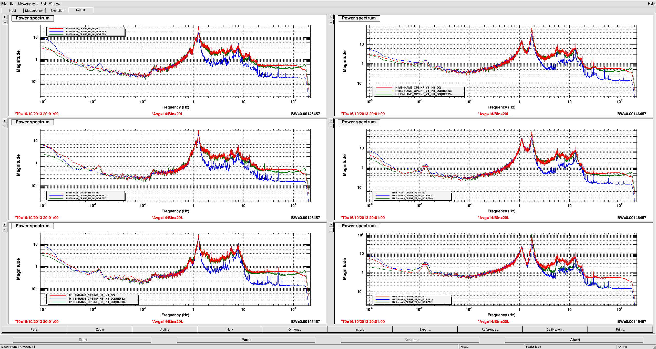
 After fixing the problems I took spectra under three conditions

   Multiple grounds (electroncs room and chamber) these were bad

  Single ground in the electronics room, red and green lines in the attached png (clean room on/off are the differences)

  Single ground at the chamber, blue lines in the attached png


   Given that set of data i think that we should plan on converting to a single ground at the chamber.


   The attached pdf shows one spectra converted to m/rthz and the expected noise (we have measured something close to the expected noise on the bench for every unit in use)

  I don't really know what to say about this except yuck


Images attached to this report
Non-image files attached to this report
Comments related to this report
richard.mittleman@LIGO.ORG - 15:31, Friday 18 October 2013 (8168)

I left the CPS on HAM6 with a signal ground (+) at from the electronics room, the boxes are not in contact with the cable trays, there is an extra ground which connects the two boxes via the sync cable

H1 PSL
jeffrey.kissel@LIGO.ORG - posted 16:51, Wednesday 16 October 2013 (8130)
PSL FSS transmitted power drifting downwards
(Stefan, on Jeff's computer)

The FSS wasn't locking anymore, because H1:PSL-FSS_TPD_DC_OUTPUT fell below the threshold value of 0.5V. Attached is a 90day trend of the  H1:PSL-FSS_TPD_DC_OUTPUT and H1:ALS-C_FIBR_INTERNAL_DC_POWER. Both channels thow the same trend, i.e. the power loss is real.

For now I lowered the threshold to 0.4V.
Images attached to this report
LHO General
dale.ingram@LIGO.ORG - posted 12:21, Wednesday 16 October 2013 - last comment - 15:46, Wednesday 16 October 2013(8124)
Wednesday Midday
Jeff B will take the ops chair this afternoon.

** We've started strip tools on a TV screen and on an ops workstation screen to monitor the pair of vacuum gauge readouts on both ends of the X1 arm section (between the CS and MX) where insulation is coming off.  These are the PT-343 and PT-144 cold cathodes. 
** Hugo will make remote measurements on HAM3 this afternoon.  We're not aware of other HAM3 work that would conflict with this.
** Filiberto worked on ISC cabling in the racks near H1 PSL this morning.
** Gerardo and Thomas have been working on the ACB at the LVEA test stand.
** The ETMX and TMS speedometer needles noticed Betsy's entry into the chamber at EX.
** Intermittent dust alarms in the low hundreds (3um) have occurred on the vac prep and diode room dust monitors through the morning although it seemed that people were not in these spaces.
Comments related to this report
jeffrey.bartlett@LIGO.ORG - 15:46, Wednesday 16 October 2013 (8129)
13:45 Betsy W. working at SUS test stand in LVEA
14:01 Travis S. working on cabling on ITMX
15:20 Rich M. and Greg G. out to End-X to work on HEPI shift of BSC9
16:00 Gerardo M, Thomas V, Mitch R, and Apollo crew installed the ACB-X Suspension.  
H1 SUS
betsy.weaver@LIGO.ORG - posted 15:51, Tuesday 08 October 2013 - last comment - 10:52, Thursday 17 October 2013(8054)
ETMx SUS cables connected

Betsy, Travis

This afternoon, we connected the 5 ETMx SUS cables and the ringheater cable to the inside of the feedthru flange.  We then had issues with signal faults.  We investigated and found the out-of vac cables not plugged in well at the outside of the feedthru.  Apon fixing, all looked well with the signals.  The suspension is still not fully suspended although we pulled out all of the extra teflon stopping brackets and prepped it for full unlock after SEI is done float/balance, after IAS is done figuring out where to put us.

Comments related to this report
jim.warner@LIGO.ORG - 10:52, Thursday 17 October 2013 (8140)

Note - Yesterday (Oct 16) we discovered that we had incorrectly pugged the cables into the internal side of the feedthru.  This was due to the fact that the cable connectors were mounted in the table bracket slightly incorrectly.  We remedied this yesterday.

H1 IOO
sheila.dwyer@LIGO.ORG - posted 11:48, Monday 07 October 2013 - last comment - 12:36, Thursday 17 October 2013(8012)
IMC transmitted beam on IOT2L

I used thenano scan to measure a beam profile on IOT2L.  near the periscope, the vertical waist diameter is 4411um.  The horizontal beam isnot gaussian, the waist diameter fit is 4007um.  (screen shot is first image attached to this report) This was taken 3 and 1/2" from the bottom periscope mirror, the periscope height is 23 and 1/2 ", and the top periscope mirror is approx 2'8 and1/2" from the viewport.  This data is saved as IOT2L1 on the nanoscan computer.  

I moved the scan head back to  14"  behind the botttom periscope mirror, and measured 4405 um diameter vertical , the horizontal beam still is non gaussian, but the diameter is 4070 um.  (screen shot is second image attached)

This data is now transfered to http://www.ligo-wa.caltech.edu/~sheila.dwyer/NanoScanData/IO/

Images attached to this report
Comments related to this report
rodica.martin@LIGO.ORG - 12:36, Thursday 17 October 2013 (8143)

According to these alogs - 6403 and 6265 - the IMC Trans beam might be clipping at the HAM2 viewport. 

Displaying reports 75181-75200 of 83068.Go to page Start 3756 3757 3758 3759 3760 3761 3762 3763 3764 End