SQZTeam [Lee, Wen, Camilla, Georgia, Sheila, Keita] took new data for the ZM4 PSAMS to revisit the analysis in LHO60377, which also plugs into the analysis of ZM5's PSAMS. That log perhaps will explain more than this one. Executive summary, the SQZ beam profiling agrees rather well with the Camille M. and Co's calibrations at CIT.
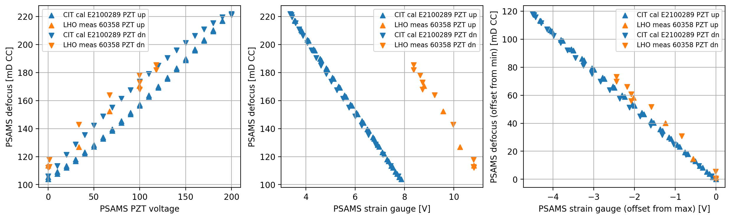
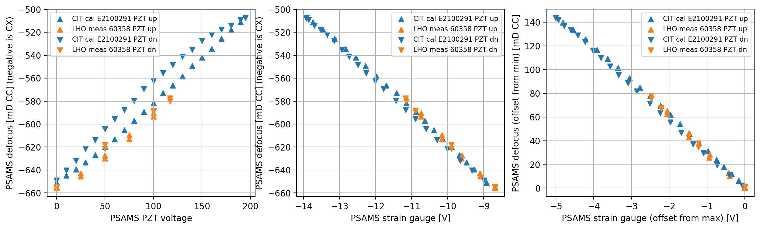
For those wishing to compare defocus with PZT's and strain gauges, the data is in ZM4_ZM5_data.mat ZM4_ZM5_data.txt (yaml). It is plotted against the CIT calibrations in ZM4.png and ZM5.png. I think the difference in the strain gauge for ZM4 is because it wasn't measured at CIT with the same bridge circuitry, and ZM5 agrees very well up to an overall offset.
The new data we took was measuring the beam before and after ZM4, using a pickoff just before ZM5. This time, we carefully monitored beam before ZM5. The beam profiler is ~9mm aperture and the beam is 4mm diameter. The ~1% region of interest (ROI) that it uses to clip its calculation spans ~8mm. We suspect that the beam in our previous measurements was drifting from defocus-deflection and the ROI was walking off the scanner, biasing the fits. We corrected this in these measurements. We also took several data points with horizontal and vertical orientation of the scanner, but except for a couple of outliers they are consistent.
Also, in my previous analysis, I was using the incorrect distance for the post-ZM5 profiling measurements. I hadn't corrected for the distance of the profiler to the ISI edge (whoops), and I realized this as I incorporated this new ZM4 data. For this reason, we did not take new ZM5 profiling measurements, since they were otherwise good.
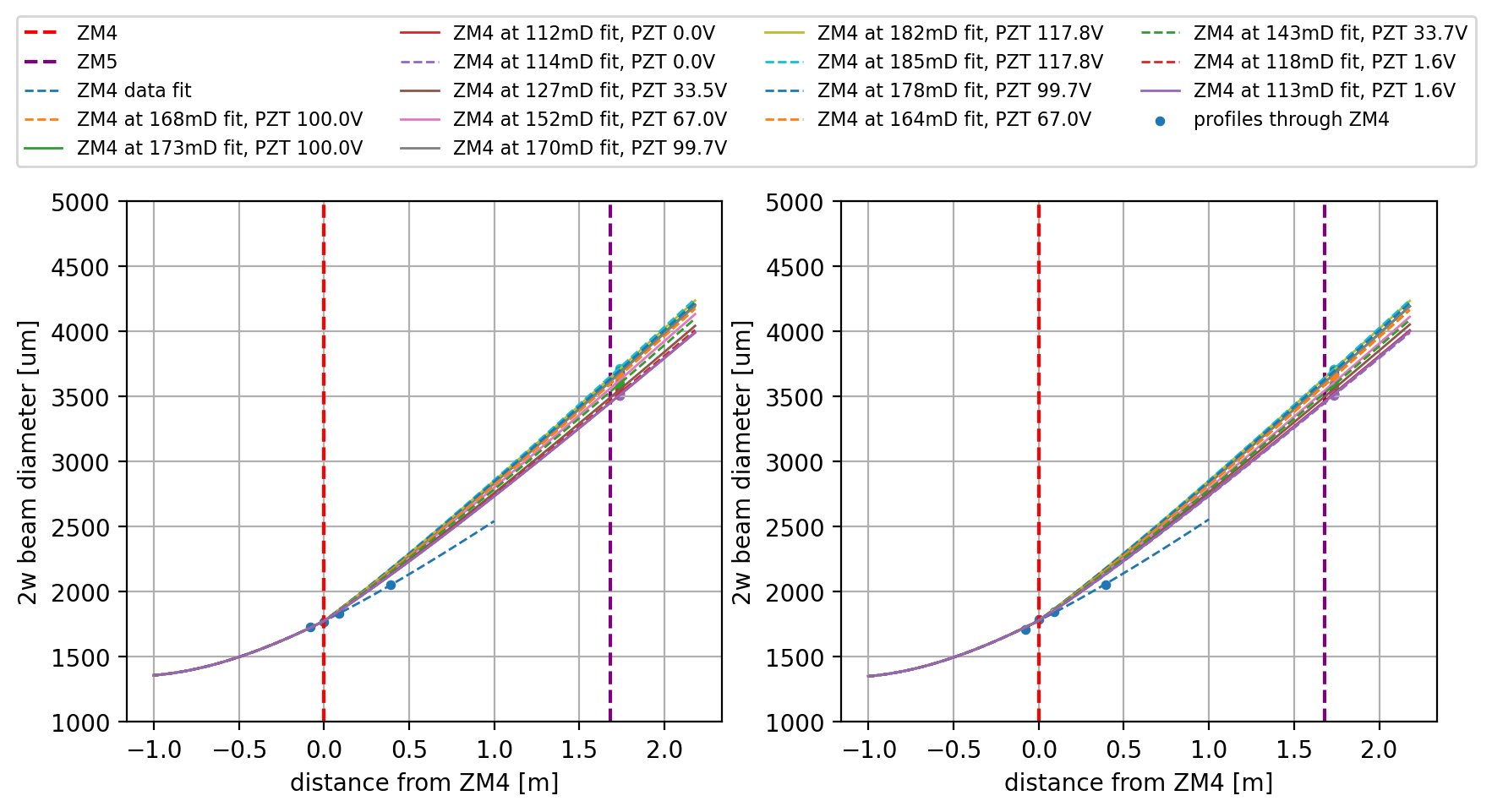
HAM7_beam_profiles.png shows the new ZM4 data, which is more consistent between X and Y now. Dashed and solids show the two orientations of the profiler
ZM4 PZT [V] ZM4 strain diam X [um] defocus X diam Y [um] defocus Y H or V
gauge [V] [mD] [mD]
------------- ------------ ------------- ----------- ------------- ----------- --------
100 8.73 3670 168.002 3651 154.063 V
100 8.73 3684 172.874 3675 162.404 H
0 10.81 3510 112.121 3525 110.137 H
0 10.81 3514 113.523 3510 104.891 V
33.5 10.25 3552 126.828 3561 122.712 H
67 9.57 3625 152.325 3609 139.448 H
99.7 8.79 3677 170.438 3674 162.056 H
117.8 8.37 3710 181.913 3708 173.858 H
117.8 8.37 3720 185.388 3713 175.592 V
99.7 8.63 3699 178.09 3695 169.348 V
67 9.22 3658 163.824 3654 155.106 V
33.7 9.97 3598 142.904 3590 132.828 V
1.6 10.8 3526 117.727 3520 108.389 V
1.6 10.8 3512 112.822 3518 107.69 H
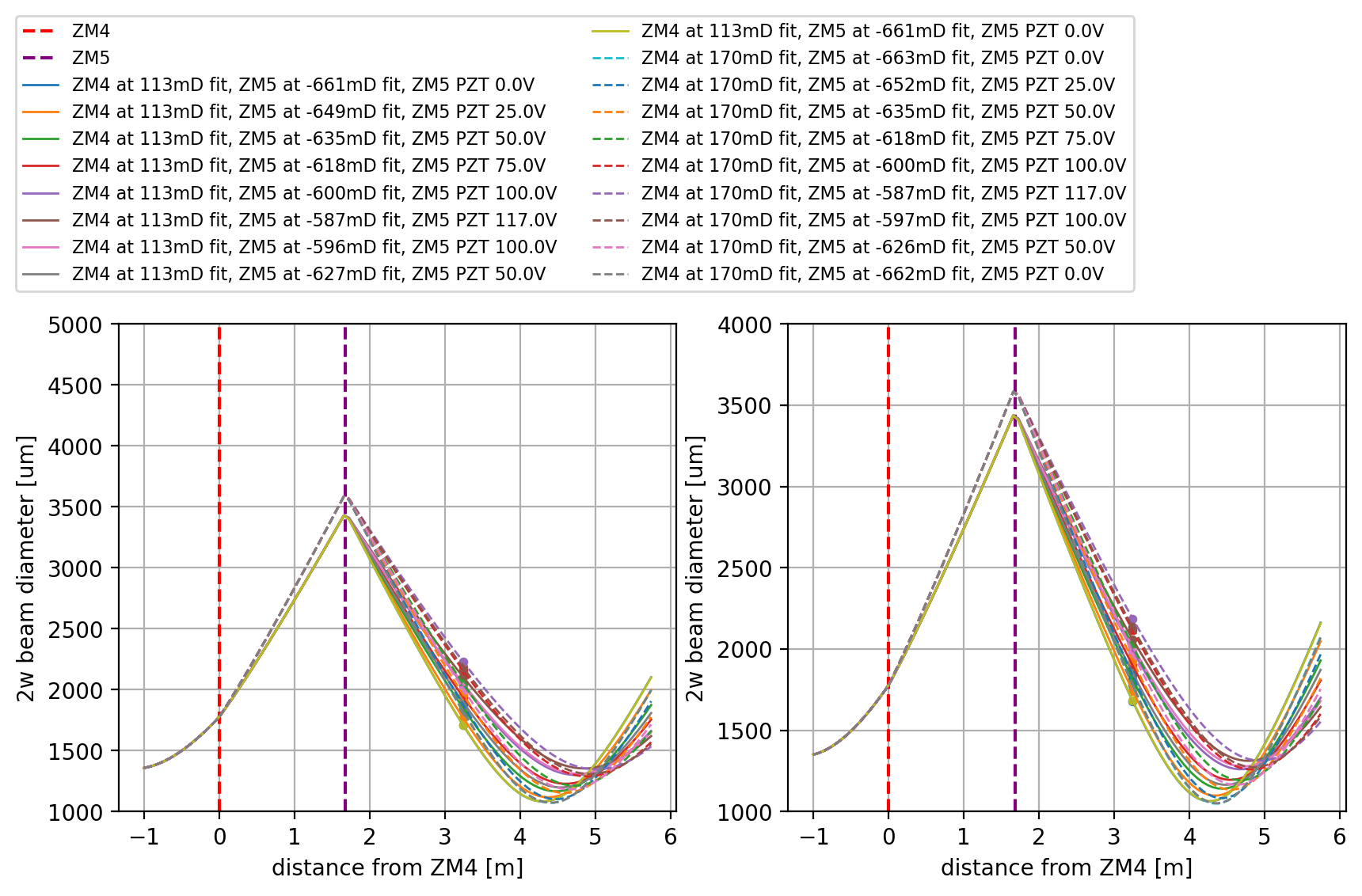
HAM7_beam_profiles_ZM5.png shows the new ZM5 fits with the correct profiler distance. The data corresponds to the table:
ZM4 PZT [V] ZM4 strain ZM4 defocus ZM4 defocus ZM5 PZT [V] ZM5 strain diam X [um] ZM5 defocus diam Y [um] ZM5 defocus ZM5 q_X ZM5 q_Y
gauge [V] X [mD] Y [mD] gauge [V] X [mD] Y [mD]
------------- ------------ ------------- ------------- ------------- ------------ ------------- ------------- ------------- ------------- ------------- -------------
0 11.03 113 109 0 -8.68 1710 -654.813 1681 -661.301 -2.634+0.863i -2.587+0.835i
0 11.03 113 109 25 -9.1 1770 -642.946 1744 -648.848 -2.709+0.919i -2.663+0.891i
0 11.03 113 109 50 -9.6 1849 -627.403 1815 -634.89 -2.813+1.001i -2.753+0.961i
0 11.03 113 109 75 -10.16 1941 -609.405 1900 -618.271 -2.942+1.111i -2.868+1.055i
0 11.03 113 109 100 -10.73 2038 -590.532 1993 -600.186 -3.088+1.244i -3.001+1.173i
0 11.03 113 109 117 -11.16 2105 -577.549 2061 -587.019 -3.194+1.350i -3.104+1.272i
0 11.03 113 109 100 -10.89 2051 -588.01 2016 -595.727 -3.108+1.264i -3.035+1.205i
0 11.03 113 109 50 -9.9 1897 -618 1853 -627.449 -2.880+1.056i -2.804+1.002i
0 11.03 113 109 0 -8.68 1711 -654.615 1683 -660.904 -2.635+0.863i -2.589+0.837i
100 8.97 170 162 0 -8.68 1821 -655.763 1777 -663.248 -2.741+0.844i -2.675+0.813i
100 8.97 170 162 25 -9.08 1875 -645.686 1838 -651.829 -2.811+0.893i -2.751+0.865i
100 8.97 170 162 50 -9.62 1960 -629.886 1929 -634.872 -2.927+0.978i -2.871+0.951i
100 8.97 170 162 75 -10.16 2052 -612.861 2021 -617.813 -3.061+1.082i -3.001+1.051i
100 8.97 170 162 100 -10.74 2158 -593.329 2116 -600.272 -3.228+1.224i -3.145+1.171i
100 8.97 170 162 117 -11.15 2230 -580.106 2188 -587.022 -3.350+1.335i -3.262+1.275i
100 8.97 170 162 100 -10.89 2183 -588.734 2135 -596.772 -3.270+1.261i -3.176+1.197i
100 8.97 170 162 50 -9.9 2006 -621.364 1976 -626.148 -2.993+1.028i -2.937+1.001i
100 8.97 170 162 0 -8.68 1823 -655.39 1781 -662.497 -2.743+0.846i -2.680+0.816i
This data is all on the files linked above. The beam parameters on the ZM5 data correspond to the SQZ beam parameter leaving ZM5. The defocus is fit from the beam size at the profiler, assuming the beam size on ZM5 from the defocus fit for the ZM4 actuator.
Finally, here are the projections of the SQZ beam to the SRM AWCmeshSQZ_SRM.pdf and OMC AWCmeshSQZ_OMC.pdf. Look primarily at the left plots. These are unsatisfyingly explained a bit at the bottom of LHO60377. These new projections extend through the full (expected) 200V range of ZM4 and ZM5, with the brown diamonds forming the grid of beam parameters accessible to the SQZ beam. The lines in the brown diamond grid correspond to 100V on either actuator. While we are "only" 99.2% with respect to (my model's) target, we can reach high 99's%, assuming my model is representative and astigmatism doesn't bite us. We are now measuring <10mD astigmatism in the actuators, though our measurements are at best \pm 5mD accuracy. This is consistent with the 5-10mD observed in the Zygo wavefront measurements, but we don't really have the accuracy to reach strong conclusions.
The "x" and "+" points in these plots represent the beam parameters of the SRC and of the arm relayed through the SR mirrors. The different colors represent different forms of wavefront detunings in the vertex. I chose the scales of those detunings arbitrarily. The contours represent the mismatch loss of a given beam size and iROC w.r.t. (my model's) "nominal" SRC mode or OMC mode, depending on which plot your are looking at.


Marie requested that someone fit the strain gauge vs defocus numbers above, for use in the P-SAMS online control. I made a quick script which imports Lee's mat file above and does a quick linear fit of the data and makes plots (see attachments).
The slop and offset for ZM4 and ZM5 are tabulated below. Here I've averaged the parameters from the x and y fits.
| ZM4 | ZM5 | |
| slope [mD/V] | -27.6 | -30.5 |
| offset [mD] | 409.2 | -924 |

J. Kissel

Encouragingly, as shown in G2102228, -v3 page 16 and 17,
	H1 SUS ZM4 (SN1) fit from the CIT data is -25.8 [mD/V]
and from page 16,
	H1 SUS ZM5 (SN4) fit from CIT data is -31.1 [mD/V]
which is consistent with the calibration (slopes) derived by Georgia above,
	H1 SUS ZM4 from LHO is -27.6 [mD/V] (7.0% difference)
	H1 SUS ZM5 from LHO is -30.5 [mD/V] (2.0% difference)

Notes:
   - From G2102228 page 10, we hope for a precision of the calibration to be within +/- 4 [mD/V], or within +/-12.5% to get us within 12 [mD] of "perfect" mode matching, which should be very achievable within the 150 [mD] of range of the PZT.
   - These measurements were taken with the beam spot poorly centered on ZM5 (identified later in LHO:60425), and as such the team plans to remeasure this data again. This shouldn't affect the calibration, but we desire unambiguous systematic free measurements.
   - The strain gauge voltage in these LHO measurements were taken directly from the "to beckhoff" output out of the HPDS driver, via a fluke, *not* as *intended* by design via a Beckhoff ADC. However, the Beckhoff ADC was incapable of reading out the voltage as it exceeded the +/- 10 Vp range of the Beckhoff ADC. A redesign of the circuit is underway to allow for the application of an analog voltage offset to the strain gauge readout voltage that both (a) comfortably brings the strain gauge voltage within the range of Beckhoff ADC, and (b) allows to compensation of any analog offset in the strain gauge voltage. This change to the circuit, nor the eventual application of an additive voltage offset should change the *slope* of the calibration, just the absolute value of the defocus in [mD] for a given absolute voltage value.