(Sheila, Alexa)
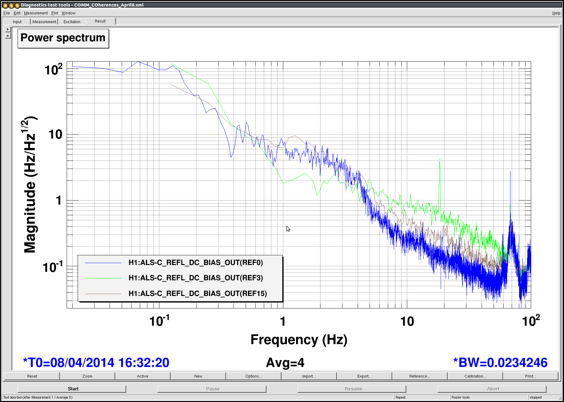
We have been trying to search for the 1/f feature present at 1-50Hz in the noise plots. We tried a few different things as described below. The noise spectrum under nominal conditions is represented in REF0-2.
- Hepa fan on/off on ISCTEX: We turned the HEPA fans on and noticed that the 1/f feature appeaared to be upconverted; the noise improved around 1 Hz, but got worse from 5-50Hz (see REF 3-5).
-
Modulation frequency: Under the nominal conditions the modulation frequency is at 24.407363MHz with a 12dB attenuator. We changed the attenuation in this path several times and found no noticable/significant difference in the noise.
- 6dB attenuation --> REF 6-8
- 0dB attenuation ---> REF9-11
- 18dB atttenuation --> REF 12-14
- Laser power: The nominal power after the second faraday is 53mW; the nominal power at the bottom periscope is 47mW. We adjusted the HWP before the faraday to reduce the power at the second faraday to 25mW. We found that the noise increased by a factor of 2 from around 4Hz to 50Hz as seen in REF 15-17.
All these plots can be found under /ligo/home/sheila.dwyer/ALS/HIFOX/COMM/COMM_COherences_April8.xml. In the set of three, the first reference is always the power spec, the second the RMS, and the third a coherence plot. I have attached an image which shows the nominal power spectrum and the cases with the HEPA fan on and one with the power reduced (NoiseSearchPic1).
For future improvement of the QPD servos, we adjusted the input beam onto the QPDs with the servo off, such that the beam was fairly centered onto both QPDS. We did not get a chance to work on the actual servos though.
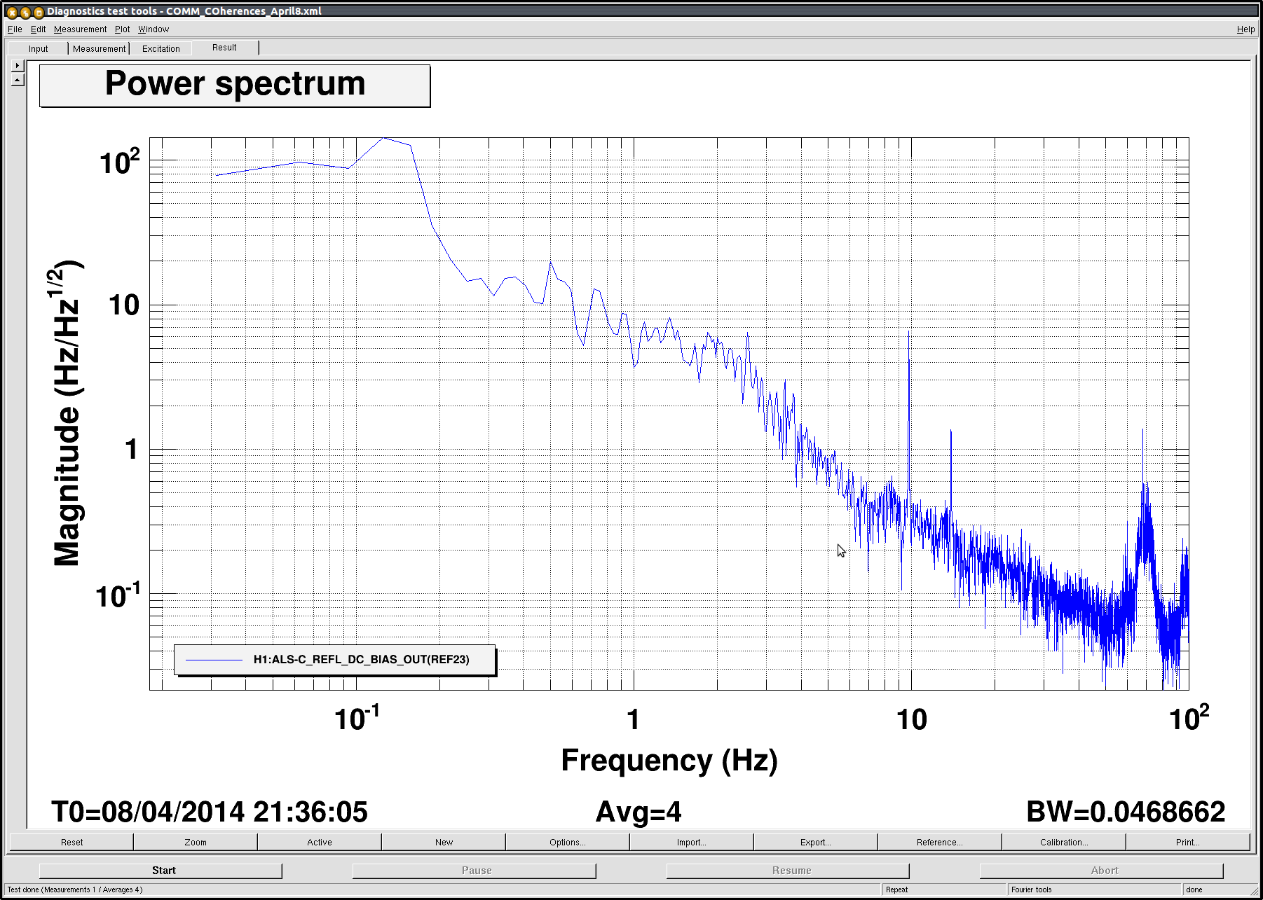
We proceeded to do some more noise hunting, but halted the effort when we saw two new spikes in the noise spectra. One spike was at 9.8Hz and the other at 13.8Hz (see second png). Turns out these are the bounce and roll modes of the suspension that must have got rung-up during an ISI trip. (Refer to Sheila's alog).
(Sheila, Chris, Alexa)
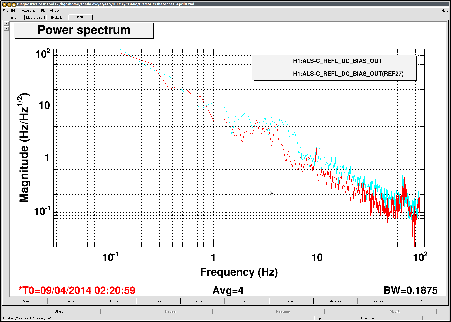
Since we had seen a difference in the 1/f noise by decreasing the laser power at EX, we decided to try the following -- we placed an ND filter in the path of the x-arm green transmission on ISCT1. With the ND filter the ALS-C_TRX counts dropped from 0.94 to 0.471. We saw an increase by a factor of 2 in the 1/f noise. We would expect a factor of Sqrt(2). We should repeat this measurement by decreasing the power further. The red line in the attached figure is the nominal spectra; while the light blue line (REF 27) is with the ND filter in place. (Overall these spectra look higher then those posted earlier in the attached alog; it's possible that this change came from alignment drift).
Subsequently, we decided to look into the noise at the COMM BBPD.
Signal from the PD w/ no RF pre-amp @ 100Hz BW:
- signal carrier: -33dBm
- secondary peak due to RF pick-up: -73dBm
- shot+dark noise/analyzer limit: -100dBm
With PD blocked and no RF pre-amp @ 100Hz BW:
- RF pick-up signal: -69dBm
- noise floor: -100dBm
With PD blocked and RF pre-amp (+13dBm) @ 100Hz BW:
- noise floor: -93dBm
- RF pick-up had several peaks: -51dBm, -59dBm, -60dBm, -61dBm
Instead of using the beatnote signal from the PD, we used a signal generator (-31dBm at 79.8Mhz) to lock the PLL and measured the in loop noise spectrum (with the input gain of the PLL at -25dB w/ the two compensation filters off). We will posts plots tomorrow. At first glance; however, this does not appear to be the 1/f noise source we have been hunting.
I have attached the plots and data we collected last night. The noise spectrum was measured out of IMON of the PFD with the PLL locked to a signal generator instead of the PD signal. This noise spectra is loop suppressed by the COMM PLL loop. The COMM PLL had an input of -25dB with the two common filters off (unlike the nominal settings). We took a OLTF of this modified loop.

