Chris, Keita, Evan
Today we were able to lock the outer ISS loop with the modecleaner at 20 W (and no interferometer). We looked at several PSL/IOO PD signals (the FSS transmission PD, the ISS inner-loop PDs, the IM4 transmission PD, and the ISS outer-loop PDs) and tried to understand their behavior in different ISS configurations.
Naively one would expect all these signals (except the in-loop ISS PDs) to agree with each other, since they should all be out-of-loop sensors for the RIN leaving the PMC. Together, these signals monitor three of the four PMC ports: the FSS transmission sees the RIN of one port, the out-of-loop inner-loop ISS PD sees the RIN of another port, and IM4 trans and the out-of-loop outer-loop ISS PD sees the RIN of yet another port.
These are the behaviors we observed (see attached pdf):
- When neither ISS loop is closed, both the FSS and IM4 transmission PDs see the noise of the HPO (about 1×10⁻³/Hz1/2 at 10 Hz). From 10 to 100 Hz, these PDs are coherent with each other and with the HPO PD. All four of the ISS PDs are swinging rail-to-rail in this configuration, so they are not useful. [Apricot traces.]
- When the inner ISS loop is closed, the FSS PD, IM4 PD, and outer-loop ISS PDs see a RIN that is a few times 10−5/Hz1/2 at 10 Hz, with a 1/f slope. These three signals are coherent with each other between 10 and 100 Hz. However, the inner-loop PDs are in some parallel universe in which the inner-loop appears to be happily stabilizing the laser RIN to better than 10−6/Hz1/2 at 10 Hz. The inner-loop PD signals have low coherence with the FSS, IM4, or outer-loop PDs between 10 and 100 Hz. [Red and blue traces.]
- When the inner and outer ISS loops are closed, the outer-loop PDs seem to behave sensibly. The out-of-loop RIN is slightly better than 10−7/Hz1/2 at 10 Hz. The IM4 PD more or less agrees. However, the FSS RIN seems to show no change from the previous measurement (inner ISS loop only), and no longer has very much coherence with the IM4 and outer-loop PDs. The FSS has some coherence above 100 Hz with the outer-loop PDs. The inner-loop PDs now see the 1/f RIN of the FSS PD, and they are coherent with this PD. [Purple and green traces.]
We think that a possible explanation for these effects is that both ISS PDs are seeing some correlated noise that is not seen by either the FSS PD or the post-IMC PDs. In this scenario, the inner-loop ISS would suppress the HPO noise but impress this correlated noise on the light entering the PMC.
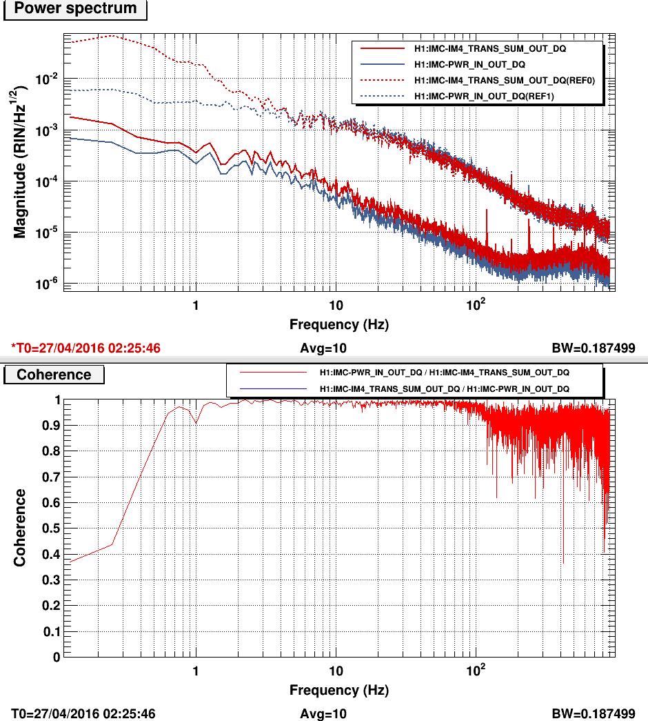
Briefly we entertained the idea that the light circulating in the PMC could be multimoded (either from the NPRO or the HPO), but judging from the RIN before and after the IMC, this seems to not be the case (png attachment).
One other idea is that some of the 808 nm light is getting through the PMC and onto the ISS.

Is this really incompatible with jitter? There are a lot of variations visible on the PMC reflected camera. The finesse of the PMC isn't that great (~100), and neither is jitter supression. If there is a static misalignment into the PMC, there would also be a linear term for the jitter to intensity conversion. The two inner loop detectors see rather different signals at 10Hz, if the inner loop is engaged but not the outer one.
Certainly the jitter seen on the IMC WFS is worse than before the HPO turn-on.
Before the turn-on, the jitter below 100 Hz was 1 nrad/Hz1/2 or so (LHO#21212). Now it is 10 nrad/Hz1/2 at 10 Hz, with a 1/f slope.
The attachment shows IMC signals with the inner ISS loop off (dashed) and on (solid).

Update: BS alert. Read the next entry.
Jitter is much larger than before, but the jitter alone doesn't seem to explain all of our observations at the same time when the 1st loop is closed but the 2nd loop open.
PDA=P+a*J+Sa, PDB=P+b*J+Sb, IM4=P+x*c*J+Sim4
P is the intensity noise leaving the AOM. When the loop is open it's just the free running noise P0.
J is the beam jitter (01 amplitude relative to 00) coming out of PMC.
a, b and c are the jitter to intensity coupling at PDA, PDB and IM4 trans due to clipping or diode inhomogeneity or whatever.
x is the attenuation of 01 mode amplitude by IMC, which is about 0.3%.
Sa, Sb and Sim4 are the sensing noise.
When 1st loop is closed, J is imprinted on P:
P=P0/(1+G) - G/(1+G) *(b*J + Sb) ~ P0/G - b*J - Sb,
PDA ~ P0/G + (a-b)*J +Sa-Sb,
IM4 ~ P0/G + (x*c-b)*J + Sim4-Sb ~ P0/G -b*J +Sim4-Sb. (note x=3E-3.)
where G is the OLTF.
Allowing some conspiracies but not extreme ones, lack of coherence between PDA and IM4 is explained in either of the following:
- b~0, PDA~a*J, IM4~P0/G+sensing.
- a-b~0 (e.g. common clipping like a particulate on the AR side of the PMC mirror), PDA~P0/G+sensing, IM4~b*J.
The first case is false because swapping PDA and PDB makes no difference in IM4.
In the second case, PDA spectrum should look like all sensing noise, but this "sensing" noise in reality is big at 10Hz.
So, even if the clipping effect is common in PDA and PDB so the PDA and IM4 becomes incoherent, we need another noise that is not unlike big sensing noise, i.e. of about the same amplitude on PDA and PDB, is incoherent between PDA and PDB, and does not appear on downstream sensors.
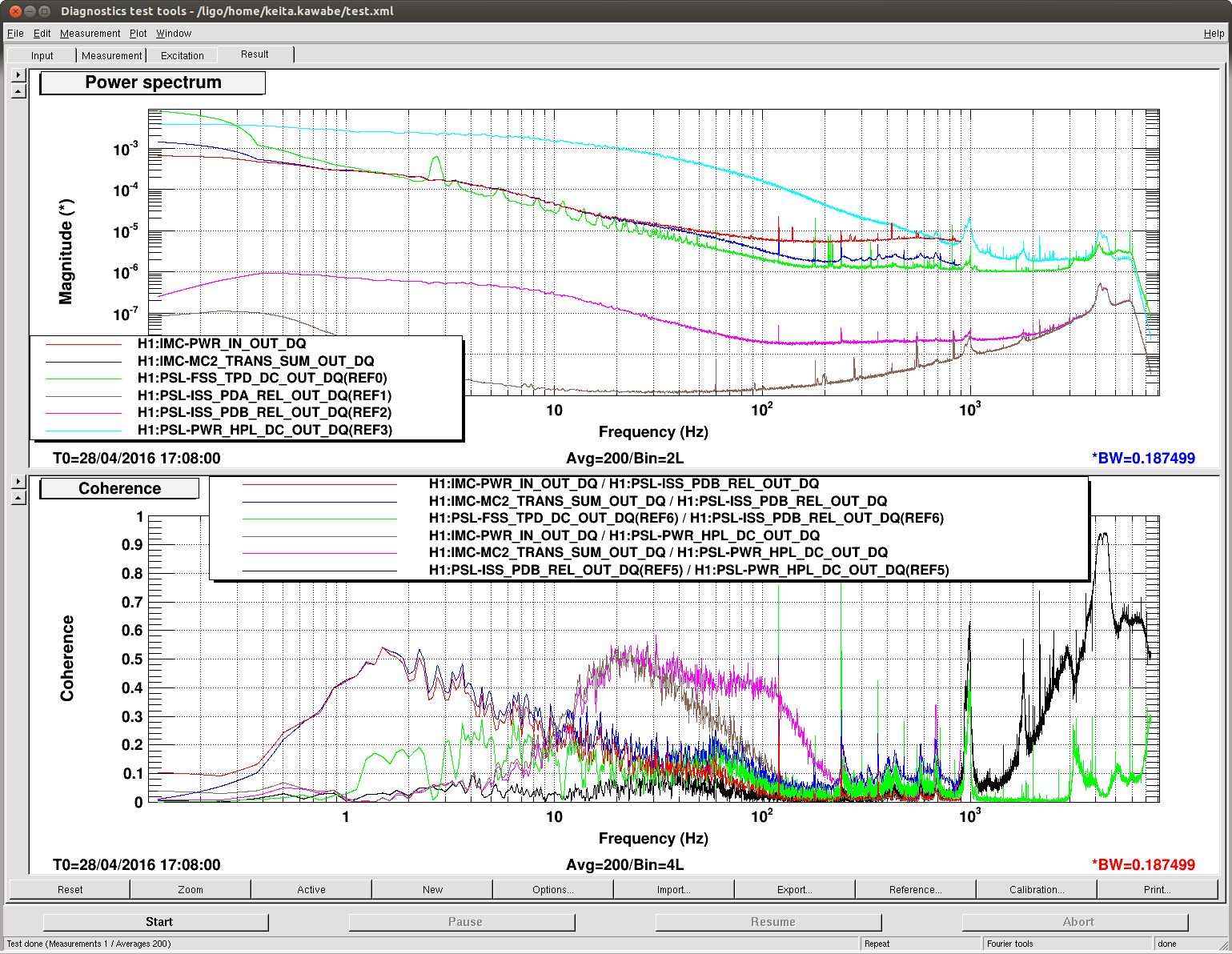
I take my words back about PDA-downstream coherence.
I was looking at the coherences from this morning, and it seems like when only the first loop is on, 1st loop out of loop sensor is coherent with downstream sensor before and after the IMC (attached, bottom red and blue). The plot is calibrated in RIN.
Note that we switched the control photodiode from PDB to PDA last night, so in this plot the out of loop sensor is PDB. I switched them back again at 17:49:10 UTC.
Anyway, out of loop sensor is more coherent with downstream sensors than HPL monitor is at f<10Hz (bottom red|blue VS brown|pink), but HPL is more coherent from 10 to 200 Hz. Difference between bottom brown and bottom pink probably doesn't mean much, just the noise floor difference between IMC-PWR and MC2_TRANS.
Some thinking necessary, but at the moment I cannot say that jitter cannot explain everything.