jeffrey.kissel@LIGO.ORG - posted 14:35, Friday 25 February 2022 (61927)
H1SUSETMX PUM Driver (and, newly, AOSEM) Response Compensation Installed (and, newly, with Always ON, Zero Crossing switch settings)
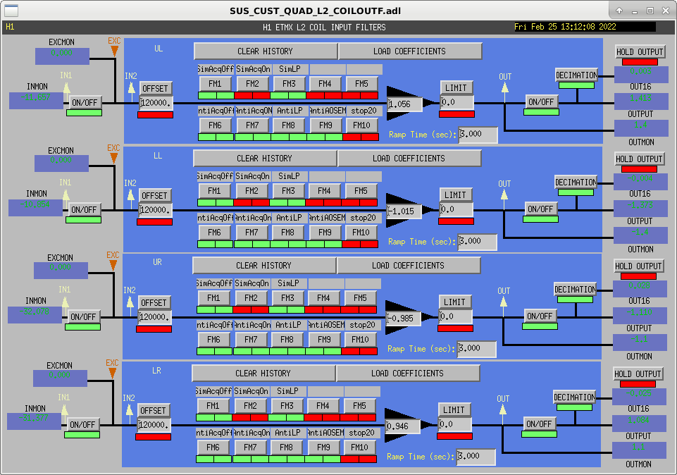
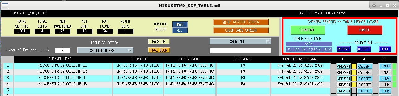
J. Kissel

Following the measurement & fitting (LHO:61313), and subsequent modeling of systematic error impact of various levels of compensation accuracy (LHO:61729), I've installed the updated compensation (in the ETMX_L2_COILOUTF filter bank) for the analog frequency response change to the H1SUSETMX PUM (or "L2") driver (described in E2100204, installed in Dec 2021).

While the modeling effort (LHO:61729) only discussed State 3 for brevity, and "only" the analog low-pass filter in State 3 changed, I also installed updates to the compensation for the Acquire ON and Acquire OFF response as well, because previous measuring / fitting attempts (47166) were flawed: the measurement was done with the AOSEMs still engaged, leaving the AOSEM inductance zero in play which confused the fitting routine. Let's be serious, I really just didn't know what I was doing and I was rushed. Now I'm far more confident in my results because I understand the system much better, and I had the time to calmly measure all the pieces of the puzzle independently. The differences to State 1 and State 2 are small, but now *any* state we choose to run in during observation will be supremely compensated (at the 0.1% / 0.1 deg level, at least below 1 kHz), rather than just "OK" compensated (at the 1% / 1 deg) level.

In addition, all the switchable compensation filters (the "Sim"s in FMs 1-3 and "Anti"s FMs 5-7) have all been converted from "Zero History" input and "Immediately" output to having their input "Always ON" and output set to "Zero Crossing." This feature of the coil driver switching had been lost in the sands of time: having recently re-explained "how the switching and compensation works and why" to Brad, I remembered a slide from a 2009 presentation of mine, G0900112 Slide 9 (be sure to download the .pptx as the animations are critical to the point), and the last bullet on there covers that, under this "SimDW," "AntiDW," and "DW" "dance of the de-whitening plum fairies" model of compensation, the switching should be done on a Zero Crossing in order to minimize glitching that may result from the large, high frequency, gain changes between State 2 and State 3 when we run "LOW NOISE COIL DRIVERS" after achieving full IFO lock/resonance on our way to NOMINAL LOW NOISE.

Finally, for the first time ever, and motivated by the modeling work, I've included an AntiAOSEM filter, which compensates for the non-negligible ~855 Hz zero that arises from the coil's inductance. This filter remains ON at all times, regardless of the state of the coil driver. As such, because there's no intent to ever switch this filter on the fly, I left the input and output filter switch settings as "Zero History" and "Immediately."

Note: I've left the L2_COILOUTF gains as is, bu these will need to be retuned, since (a) the measurement method (LHO:11392 and LHO:9453).  involves driving a line a ~3 or 4 Hz, and there was significant frequency-dependent systematic error in the compensation around that frequency which was unrelated to the actual overall gain imbalance, and (b) there're brand new R and C electrical components in the State 3 path, so I anticipate some ~1% level change in the over all gain (and the coil balancing method claims to achieve 0.1% level accuracy in compensating for gain imbalance).

Attached is a screenshot of how the new filter bank looks when the BIO_REQUEST for L2 is set to State 2.
Also attached is a screenshot of me accepting the turning ON of FM9, which is where I've chosen to house the AntiAOSEM compensation.
Also, also attached is a new version of the State Machine Diagram, conveying which state has which analog response, and corresponding the compensation scheme.
Finally attached is a list comparing old vs. new filter poles and zeros.
Images attached to this report
Non-image files attached to this report

