Since violins are super high and annoying, DCPD whitening chassis was pulled and the unused OMC B filters were changed to provide less whitening at the violin frequency and up. (The chassis can support two OMCs, each having two DCPDs, and we've been using OMC A filters until now.)
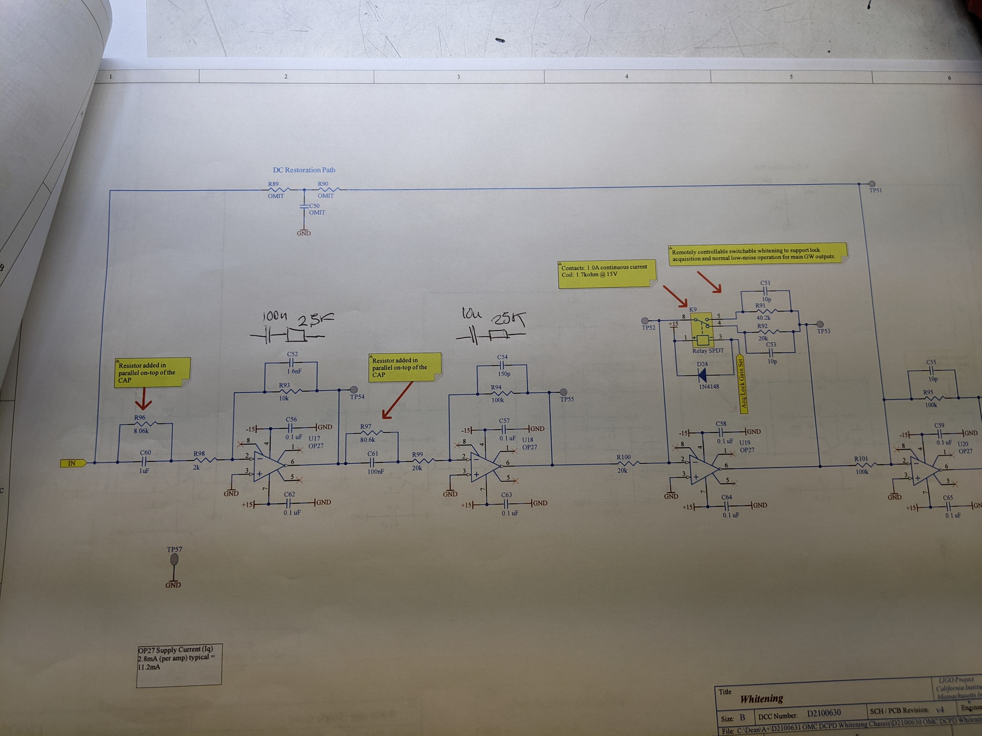
In each of the whitening stages, a feed back cap was replaced with a cap and a resistor in series. See attached.
In addition to already existing zeros and poles, double poles at 127.324Hz and double poles at 636.62Hz (i.e. a factor of 25 gain duction in total for high frequency).
Modified chassis was put in place, cables were swapped to use OMC B filters. Daniel is working to quickly put the dewhitening filters in the frontend.
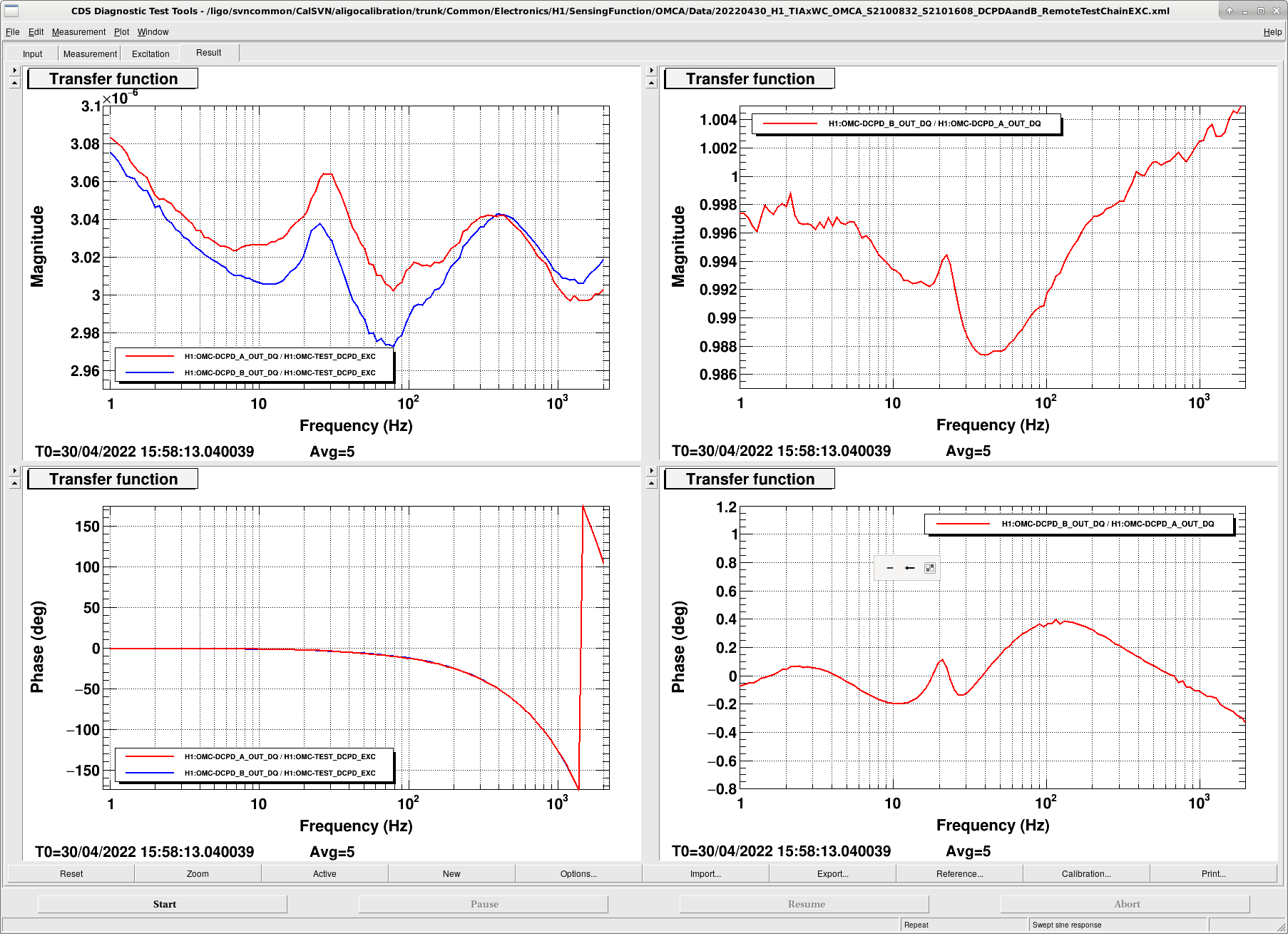
Daniel put the filter in and made this measurement. It's fairly flat, compensation is good.

Tagging the CAL group.
*sigh*
#FridayNightModsToCriticalHardware

Implicit in Keita's comment is that Daniel has already installed compensation for this whitening filter change.
The compensation lives in the OMC-DCPD_A and OMC-DCPD_B filter banks, under FM8, called "antiB," which for both DCPDs, has the following design:
     zpk([91.44;111.63;127.32;127.32],[18.1;22.3;636.62;636.62],1,"n").
This *replaces* the "antiWh" filter that has Dripta's fits from both channels (fits are in LHO:62187 and the compensation scheme is described in the first half of LHO:62653).
The bold zeros and poles are what's new, and you'll notice that these are the same analytically calculated values that Keita quotes above.
The non-bold zeros and poles, i.e. [91.44;111.63]:[18.1;22.3] are Dripta's fits for DCPDA, but these have been loosely copied over to DCPD B as well.

The measurement that Keita posts is a repeat of what's described in the second half of LHO:62653, namely it includes *many* more electronics components than just the whitening chassis, as well as the all compensation. BUT, if the whitening chassis filter is the only thing that's changed, and Daniel has compensated for it, then this DAC driven measurement should remain "fairly flat," and thus the conclusion that "the compensation is good."

The compensation for DCPD B (i.e. the blue trace in from the above new measurement) is not as good as A, because it's a (loose) copy of A's fitted results.
But, this is a whole different board (the OMC B board) that's been modified, so there's no reason to complain about loosely copying the careful fits, because if we'd look carefully, the fits to this OMC B chain would be different anyway.
In a way, it's encouraging that these two channels on a totally different board can be compensated well with the fit results from another channel on another board.

*sigh* Have a good weekend y'all!
Since there was some rise in the measured TF at higher frequencies, I adjusted the pole frequency from 127.32 to 130.28Hz, The first attached plot shows the new TF. The second plot shows the new (blue) and old whitening TF. At 500Hz there is a good factor 10 less gain; about 4dB at 100Hz and 10dB at 200Hz.
Changes to OMC B side of the board (D2100630; s/n S2101608):
- C12 from 1.6nF to 100nF in series with 2.49K
- C14 from 150p to 10nF in series with 24.9K
To change between the 2 whitening filters:
- Turn off the power to the DCPD (rear chassis, or front panel switches)
- Switch DB25 cable at front panel between A and B.
- Switch DB9 cable labeled "to AA" between A and B.
- Update the whitening compensation in the DCPD_A and B filter banks:
Select FM3 for A side, or FM8 for B side.
Just to be super clear, when Daniel says
    "I adjusted the pole frequency from 127.32 to 130.28Hz"
in comment LHO:62903, he means he's adjusted the OMC_DCPD_A and OMC_DCPD_B digital compensation filter to be the following:
    FM8    "antiB"    zpk([91.44;111.63;130.28;130.28],[18.1;22.3;636.62;636.62],1,"n")
(i.e. it's not that he made further changes to the electronics.)

We are still actively using this new B path.

Also, I've copied over Daniel's latest measurement from where he keeps his person store of these results,
    /ligo/home/daniel.sigg/Desktop/DCPD/DCPD_220430_A.xml
to a more permanent place with a more explicit name:
    /ligo/svncommon/CalSVN/aligocalibration/trunk/Common/Electronics/H1/SensingFunction/OMCA/Data/
        20220430_H1_TIAxWC_OMCA_S2100832_S2101608_DCPDAandB_RemoteTestChainEXC.xml

Attached is the same transfer function, but cast into linear magnitude rather than dB so one more easily read off this compensation scheme's the percentage discrepancy from flat. In short, if we expect this transfer function to have a gain of ~3.051e-6 [mA / DAC ct] at 1 kHz from LHO:62653, then the residual frequency-dependent systematic error is of the order +/- 2%.

Note, I'll have to work out what Daniel's description of these components means for the ~10 kHz super Nyquist poles, but hopefully we don't like this change so much that we run with this system long enough to need to change the plan for the low-latency calibration pipeline's GDS compensation of these super-Nyquist poles.
Here's a plot demonstrating the difference between
    - the 2022-03-16 meas't using the OMCA DCPD path,
    - the 2022-04-19 meas't using the OMCA DCPD path, and
    - the 2022-04-30 meas't using the OMCB DCPD path

Recall this measurement drives through a large collection of electronics and compensation, so it's pretty convoluted to attribute a change to one particular component if other things are still "on the move." But, we can still try -- assuming the only thing that has changed.

Our best guess of why there's a change between the March and April data is non-linearity of the same whitening chassis channel (waives hands furiously about different excitation levels, even though they were the same).

There *should* be a big difference between the April 2022-04-19 and what I'll call the "May" 2022-04-30 data:
    - It's a brand new whitening filter board (OMCB's instead of OMCA's),
    - A brand new AA and ADC readout of the whitened data (switched to the "to AA" output of the OMCB path), and
    - A new compensation scheme.
and in we do in fact see this.

For example, the 10 [deg] phase "gain" seen in the ratio of the May / Apr data is due to the new components in the upper part of the RC network of the feed-back paths of the whitening filters, C12 (100nF) + 2.49k resistor, and C14 (10nF) +24.9k resistor, (see Keita's redlines of the drawing), which remove each of the 10 kHz pole frequencies that come from each stage (confirmed by Daniel's analytical modeling plots in dcpd_tf.pdf)

But, there's also still the more subtle things going on too:
    - the TIA may still be evolving as a function of temperature, and
    - there's likely jut as much non-linearity in the OMC B channel set as in the OMC A channel set, so we'd see the ratio of those two non-linear things in this data set.

A lot of me wants to say "this is a temporary change. Don't spend too much time understanding, measuring, modeling, fitting, and compensating." But I seem to not be able to help myself...