The temporary name of the models that are running on the new segregated front-end are named OMZ instead of OMC. This is temporary until we switch to this FE permanently. All channel names associated with the new system also use an H1:OMZ prefix.
The main difference between the new and old OMZ/C models are 2 additional filter modules, named DCPD_A0 and DCPD_B0, that are running in the IOP at 524kHz and are in front of the still existing DCPD_A and DCPD_B that run in the user model at 65kHz. This allows for a higher Nyquist frequency when correcting the analog low pass filters. This also requires an explicit decimation filter that can be chosen appropriately. The window comparators for the DCPDs were moved to the IOP model all together.
There are no analog AA filters now, but the 4 channels sent from the DCPD whitening chassis are duplicated 4 times to channels 0 to 15, with channels 0, 4, 8 and 12 sampling DCPD_A, channels 1, 5, 9 and 13 sampling DCPD_B, and similarly for the 2 corresponding PI channels. The later 2 will disappear with the new DCPD whitening chassis. In the IOP model each set of channels sampling the same signal are added together. Together with the fact that the low noise ADC is 18 bits, the signals are 16 times larger in counts compared to the old front-end.
Next, all filters of the OMC model were copied to the new OMZ model. Then, the filters from the DCPD_A and B modules were copied into the DCPD_A0 and B0 modules using the same poles and zeros but different digital representation due to the higher processing speed.
The first attached plot shows a comparison the DCPD signals between new and old. There is no significant difference except at the high end where the AA seems to make a difference. The second plot shows a spectrum with the full bandwidth with an added trace from one of the PI channels. The later was scaled by 1E-6 to give a similar amplitude around 10kHz.

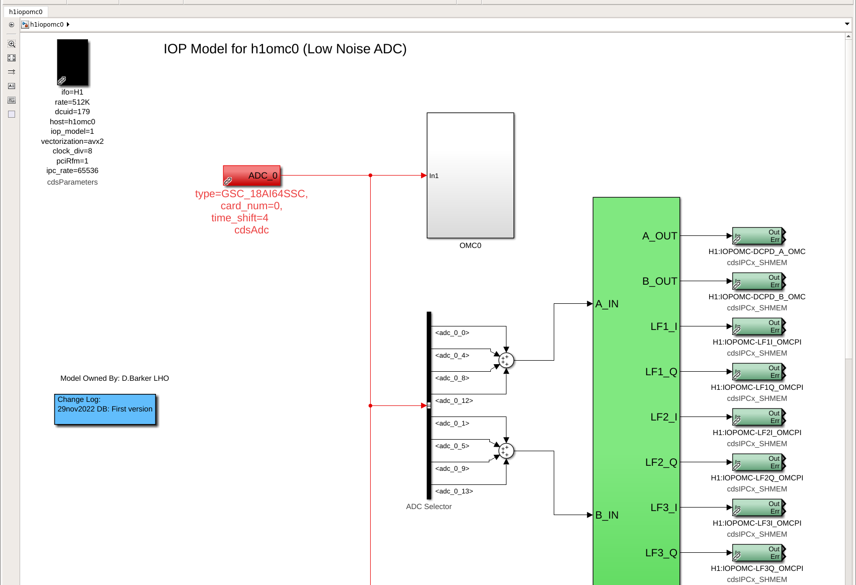
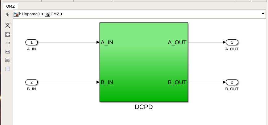
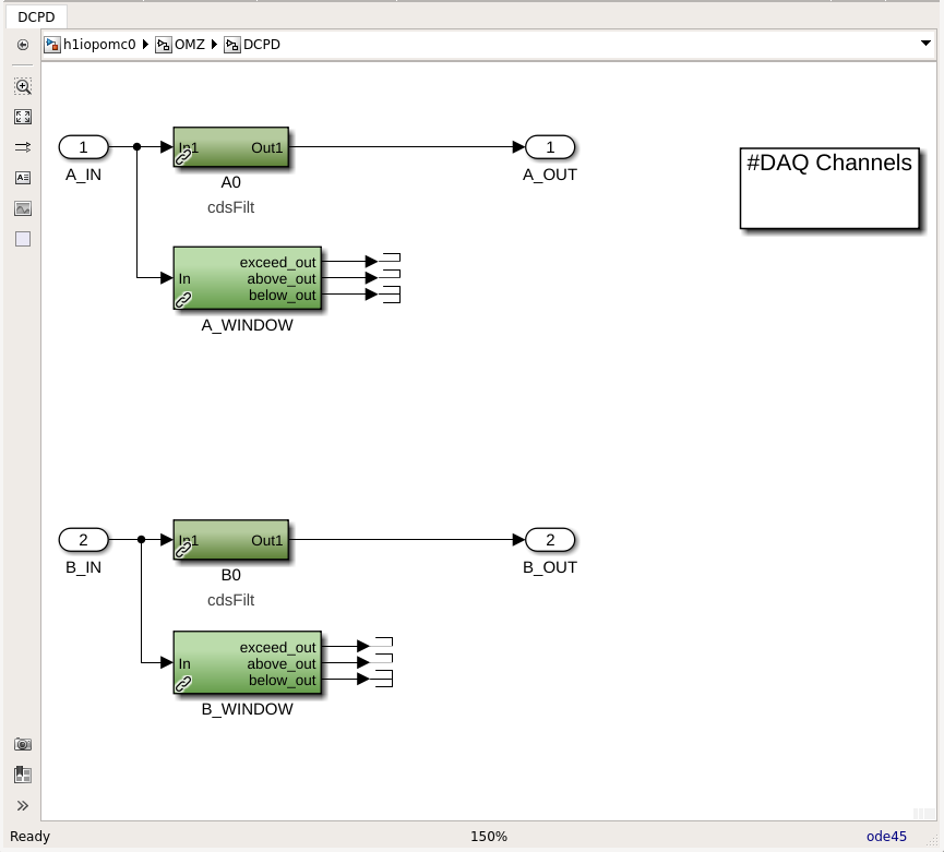
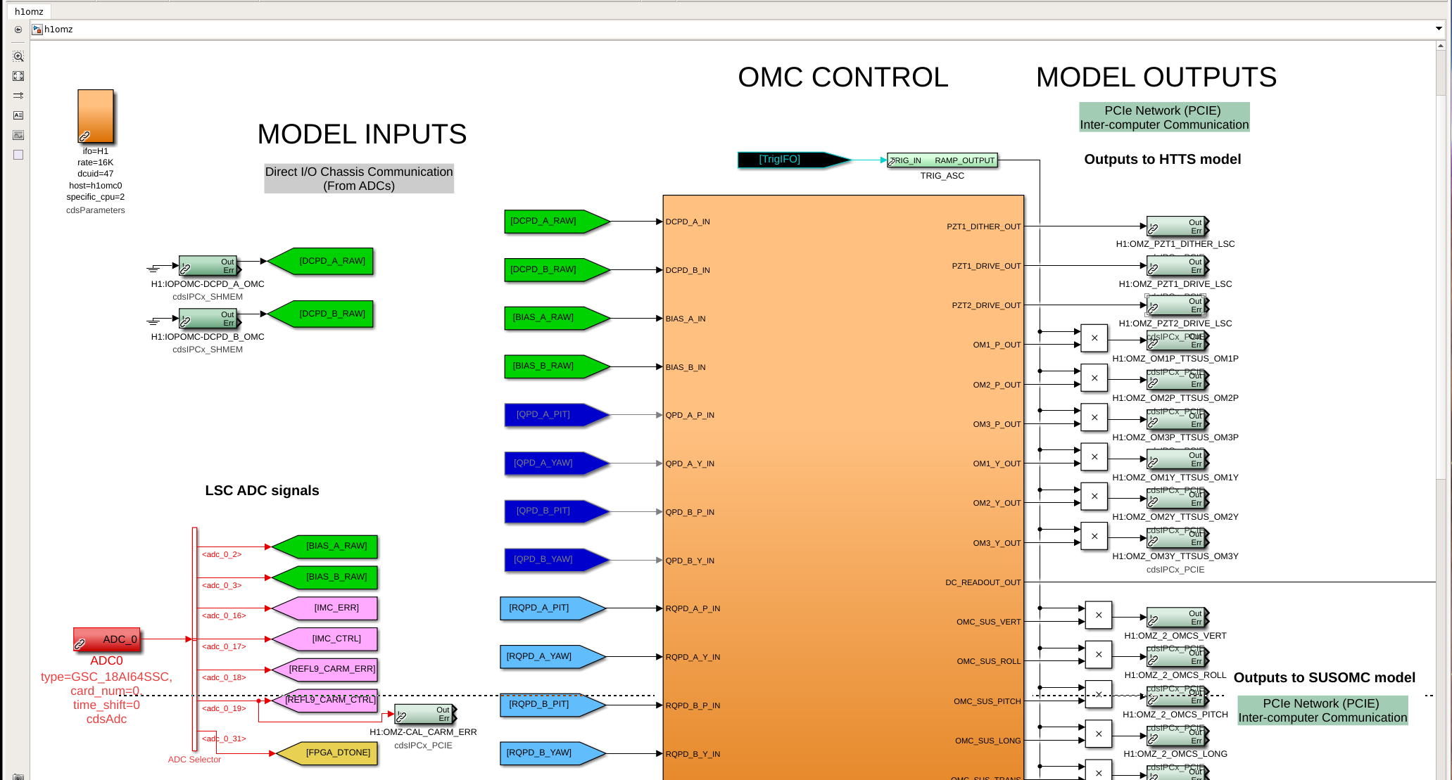
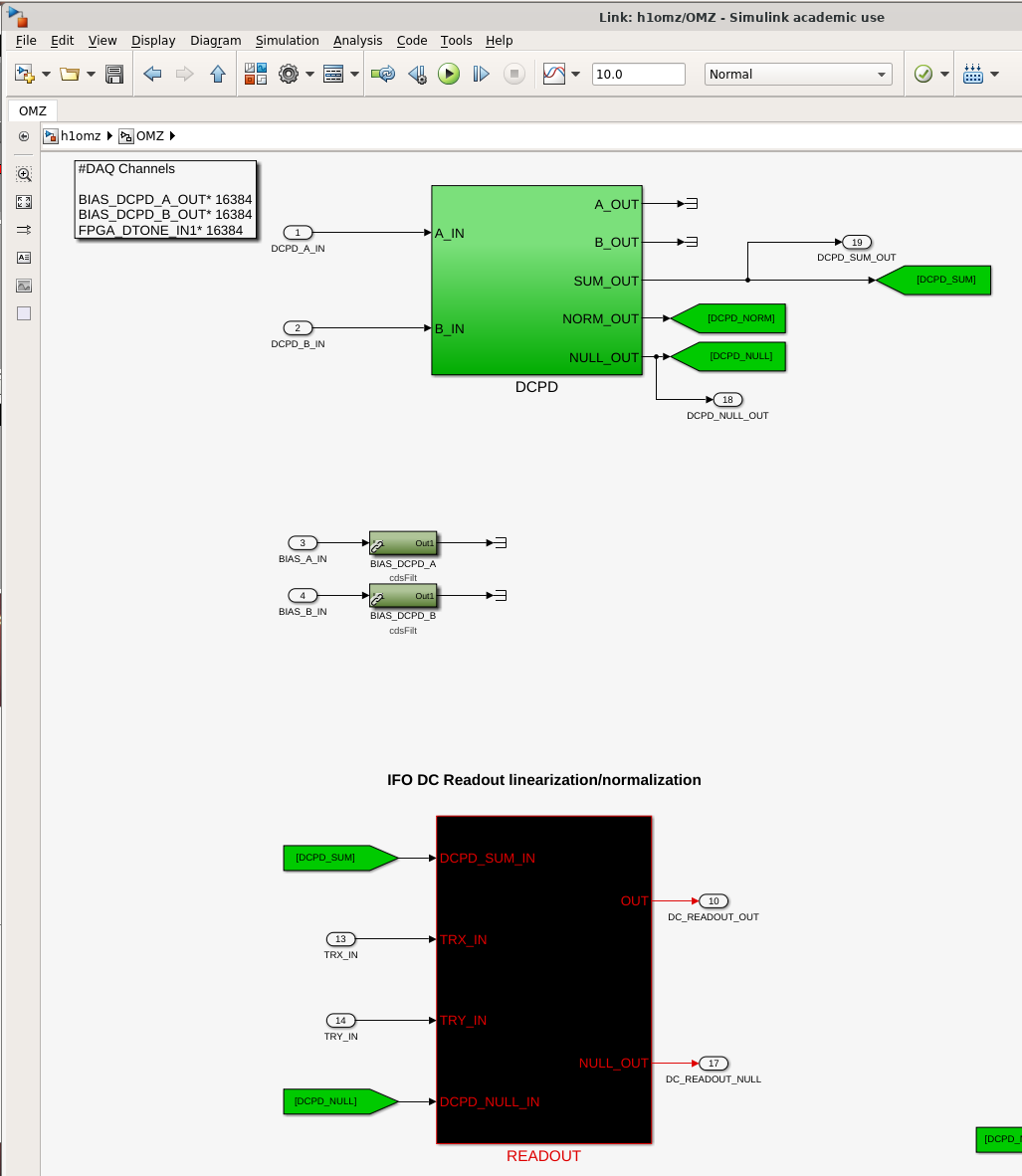
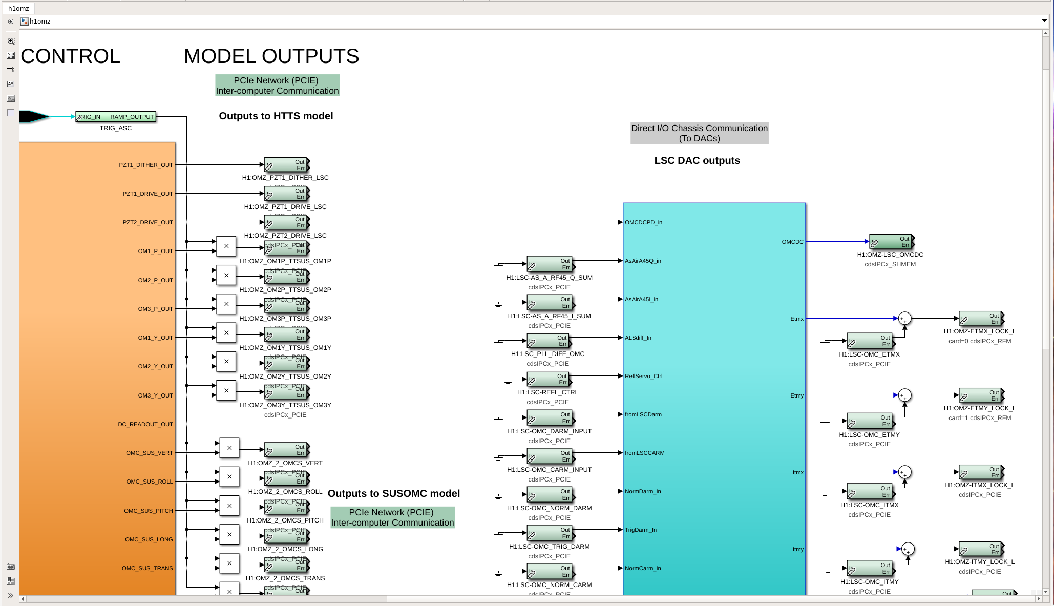
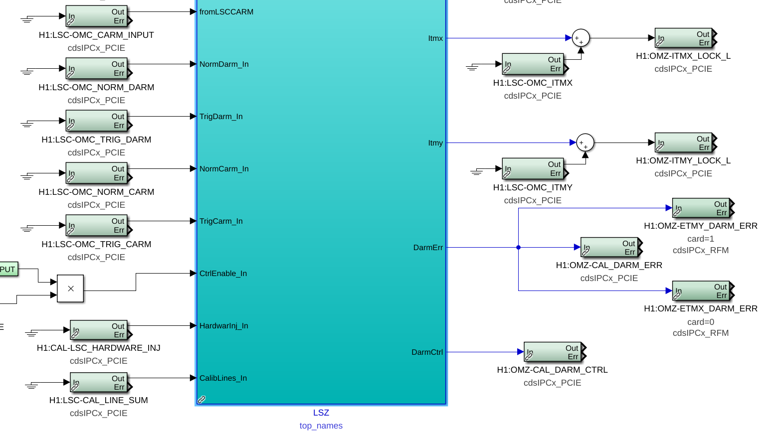
Tagging CAL & DetChar,and a few other potentially interested groups besides ISC.
ECRs E2200441 and E2100138
Technical Support Document T2200373

Adding some visual information to Daniel's verbal description -- this new "h1iopomc" and "h1omz" front-end model infrastructure recreates a lot the existing software, a replica DARM sensing chain (for now, temporarily called "OMZ" and "LSZ" instead of "OMC" and "LSC") BUT it instead uses the new segregated OMC IO chassis, with the better 18-bit ADC sampled at 524 kHz, rather than the currently in use 16-bit ADC, sampled at 65 kHz, still in the LSC IO chassis. This path gets real signals, thanks to the y-cable installed at the output of the OMC DCPD whitening chassis, covered in LHO:66330.

The key differences are with this replica infrastructure, as Daniel mentions, are that
    (1) the incoming voltage from each DCPD A and B is copied 4 times, in analog, and sent into 4 separate ADC channels, to be averaged in software in order to win a sqrt(4) in noise performance for any incoherent noise on the 4 ADC channels.
    (2) the H1:OMZ-DCPD_A0 and H1:OMZ-DPCD_B0 filter banks, that live in the 524 kHz sampled*** input-output-processing (IOP) model, h1iscomc0, are where *all* the digital signal conditioning is done, rather than the h1omc user model (living in the h1lsc0 computer, governed by the h1ioplsc0 IOP model) filter banks H1:OMC-DCPD_A and H1:OMC-DCPD_B.

In this comment, I cover a visual + written walk of the Simulink infrastructure as it stands now, today, 2022-Dec-20.
    The IOP model: h1iopomc0
        :: First attachment: This shows the upper half of the h1iopomc0 model, relevant for the OMC DCPDs. From Left-to-Right:
            . The parameter block settings are shown in orange, highlighting the model rate is "512K^^^".
            . The visual representation of the ADC card is shown by red ADC0 block
            . The ADC bus selector part (the big black vertical bar) is used to select out the 4 copies of each DCPD channel, and then they're immediately summed together
            . The sum is fed into the "OMZ" block through the ports A_IN and B_IN. (It's not visible in the screenshot, but the name "OMZ" is at the bottom of the green block, with the extra "top_names" modifier such that channels don't start with H1:IOP- but instead H1:OMZ-)
        :: Second attachment: Inside the OMZ block, we see that A_IN and B_IN are piped, unmodified, into the darker green "DCPD" block
        :: Third attachment: Inside the OMZ > DCPD block, where
            . The raw DCPD signal (well, the sum of the four copies of each DCPD signal) is fed into this new filter bank, which manifests with the channel names H1:OMZ-DCPD_A0 and H1:OMZ-DCPD_B0, is where all the digital signal processing goes. Thus far, the design intent is for these banks to contain
                + The "divide by four" gain of 0.25 to complete the average of the four copies of each DCPD A or B channel, to get it back into units of a single DCPD,
                + The (40 V / 2^18) volts per ADC counts to convert the digital signal into ADC input voltage,
                + The compensation for the ex-vacuo analog whitening's frequency response  to convert the signal into voltage input to the whitening chassis,
                + The compensation for the analog transimpedance amplifier's (aka TIA, aka front-end, aka head, aka preamp) frequency response, include a normalization at 1 kHz to convert to units of current incident on the DPCDs [Amps]
                + A convenience unit change from A to mA, a gain of 1000
                + Any/all decimation filtering in prep for the down sampling from 524 kHz to 65 kHz.
            . The raw DCPD signal is also mapped into one of Daniel's new min/max window from LHO:62310 for monitoring of saturations during times of high violin modes (note: where this pick-off happens, for better or worse, this is still actually the sum of 4 copies of the DCPD channels, not yet an average divided by 4).

    The signal conditioned output of the H1:OMZ-DCPD_A0 and H1:OMZ-DCPD_B0 filter banks then gets piped back up and out two layers, to be shipped over shared-memory inter-process communication (IPC) to the user model, h1omz, which runs on the same computer at 16 kHz. The "channels" for this shipment are H1:IOPOMC-DCPD_A_OMC and H1:IOPOMC-DCPD_B_OMC.

    The user model: h1omz
        :: Fourth attachment: This shows the upper left-hand corner of the top level of the new h1omz user model.
            . the down sampled OMC DCPD channels come in from the IPC channels seen in the above IOP model, H1:IOPOMC-DCPD_A_OMC and H1:IOPOMC-DCPD_B_OMC.
            . these are immediately piped into an instantiation of the standard library part for all OMC control, /opt/rtcds/userapps/release/omc/common/models/omc.mdl. This starts the replica of the existing path. By definition, because it's using the same library part, all the same filter banks, matrices, and other infrastructrue will be the same as in the existing current system. The *channel* names will be slightly different, because Daniel's again used the top_names feature, and also called this block "OMZ."
        :: Fifth attachment: this shows inside the omc.mdl library part,
            . The infrastructure has the signal flow as normal inside in DCPD Block, for signal conditioning,
                + H1:OMZ-DCPD_A and H1:OMZ-DCPD_B as a replica of the H1:OMC-DCPD_A and H1:OMC-DCPD_B filter banks. THESE WILL NOMINALLY BE EMPTY because all the signal processing is / should be done in the h1iopomc0 IOP model at 524 kHz as described above.
                + H1:OMZ-DCPD_MATRIX which adds DCPDA and DCPDB together to form H1:OMZ-DCPD_SUM_OUT_DQ the beginnings of the combined DARM ERR signal, which is normally H1:OMC-DCPD_SUM_OUT_DQ
            . and then the sum is sent to the READOUT block
                + This goes through the same linearization algorithm as normal with channels like H1:OMZ-READOUT_ERR
            . then the linearized signal is sent back up to the top level, as DC_READOUT_OUT, over to the "LSZ" block where its ingested as OMCDCPD_in
        :: Sixth attachment: This shows, now, the upper right corner of the h1omz top-level user model.
            . This is an instantiation of the standard library part /opt/rtcds/userapps/release/omc/common/models/omclsc.mdl, again using top_names such that channel names inheret the "LSZ" moniker rather than LSC.
                The means, as shown in the Seventh attachment, that
                + the LSC input matrix element that maps the linearized OMC DCPD SUM to DARM has the channel like H1:LSZ-ARM_INPUT_MTRX_1_1
                + *the* DARM_ERR, in this infrastructure, has the channel name H1:LSZ-DARM_IN1_DQ and
                + *the* DARM_CTRL H1:LSZ-DARM_OUT_DQ
                + One would measure the open loop gain in the presence of the excitation H1:LSZ-DARM1_EXC_DQ, and taking the transfer function  H1:LSZ-DARM_IN1_DQ / H1:LSZ-DARM1_IN2_DQ,
                 etc. etc.

        :: Finally, the DARM CTRL signal comes back out to the top level, and
            . sent to the ETMs via the long-range dolphin, RFM network on "channels" like H1:OMZ-ETMX_LOCK_L out to the ETMs. (Note that the short-range dolphin signal for the LSC feed-forward gets added in at this top level, with the same exact IPC "channels" as the current path, i.e. with channels like H1:LSC-OMC_ETMX). This H1:OMZ-ETMX_LOCK_L IPC channel is then received by the h1susetmx user model, one 16 kHz clock cycle later, in the brand-new infrastructure described in LHO:66488.
            . NOT YET, BUT IT EXISTS -- the DARM_ERR and DARM_CTRL signals sent to some future CAL-CS model to ingest, calibrate, and turn in to some version of CAL-DELTAL_EXTERNAL.

*** Something I still don't entire have reconciled in my brain between what Erik and Daniel tell me verbally and what I see in front of me:
    - Verbally: The real-time code generator c-code is not yet capable of *actually* clocking at 524 kHz. Instead, it's a 65kHz process that grabs the previous 4 and the future 4 = 8 data packets from the ADC card at 65 kHz. So technically, the decimation is two-step process from 524 kHz to 65 kHz, then from 65 kHz to 16 kHz, but both operations are done simultaneously in the 65 kHz IOP model.
    - "What I see in front-end of me:"
        :: the front-end model parameter block says "512k ^^^"
        :: the foton file says that the sample rate is 524288 Hz
When I find out more, you'll know too.

^^^ Unfortunately, someone multiplied 16 by 8 and came up with the colloquial "512kHz", rather than the truth, which is 2^14 = 16384 Hz by 32x, or 2^16 = 65536 Hz by 8x, which is 2^19 = 524288 Hz, aka "524 kHz."
This continues the walk-through of the immense amount of work that Daniel's done, where here
In this comment, I cover a visual + written walk of the MEDM infrastructure as it stands now, today, 2022-Dec-20.
Throughout the visual attachments, I show
- the existing 65 kHz > 16 kHz, "OMC" and "LSC" systems on the top of the screenshots, and
- the new prototype 524 kHz > 16 kHz "OMZ" and "LSZ" system on the bottom of the screenshots.
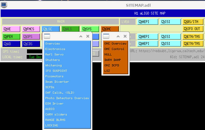
First attachment the sitemap, highlighting the menus where you can find these new screens. Specifically under the burnt orange OMC menu, at the bottom.
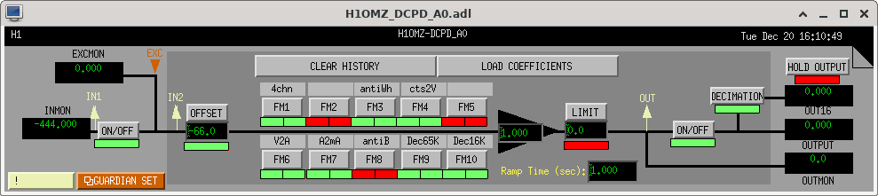
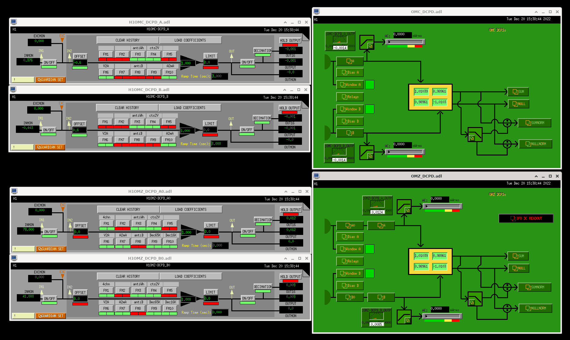
:: Selecting "OMZ DCPD" from the menu gets you Second attachment: as we learned above, the H1:OMZ-DCPD_A0 and H1:OMZ-DCPD_B0 filter banks, running at 524 kHz, contain
. the copies of signal conditioning that is already present in the H1:OMC-DCPD_A and H1:OMC-DCPD_B filter banks
+ "cts2V" The (40 V / 2^18) volts per ADC counts to convert the digital signal into ADC input voltage,
+ "antiWh" The compensation for the ex-vacuo analog whitening's frequency response to convert the signal into voltage input to the whitening chassis,
+ "V2A" The compensation for the analog transimpedance amplifier's (aka TIA, aka front-end, aka head, aka preamp) frequency response, include a normalization at 1 kHz to convert to units of current incident on the DPCDs [Amps]
+ "A2mA" convenience unit change from A to mA, a gain of 1000
AND
. new signal conditioning needed for the four-copies of the same channel, 524 kHz, version of the signals,
+ The "divide by four" gain of 0.25 to complete the average of the four copies of each DCPD A or B channel, to get it back into units of a single DCPD,
+ "Dec65K" and "Dec16K" decimation filtering for the down sampling from 524 kHz to 16 kHz.
IMPORTANT NOTE: repeat from the simulink discussion in the previous aLOG, the H1:OMZ-DCPD_A and H1:OMZ-DCPD_B filter banks, which are present only because the h1omz model has to use a common omc.mdl library part, MUST remain empty pass-throughs, since their function is covered by the A0 and B0 banks.
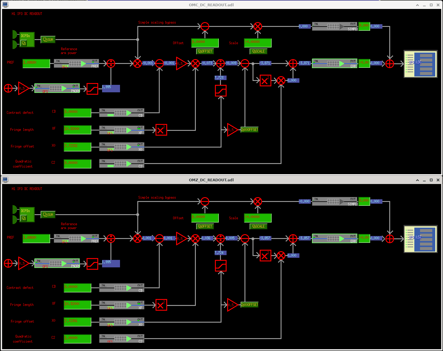
:: From the green OMZ DCPD screen, one hits the black IFO DC READOUT button in the upper right corner to get the third attachment, the usual linearization scheme. There is NO functional difference between the linearization here in the OMZ infrastructure, everything should be exact copies, and this is indeed the case.
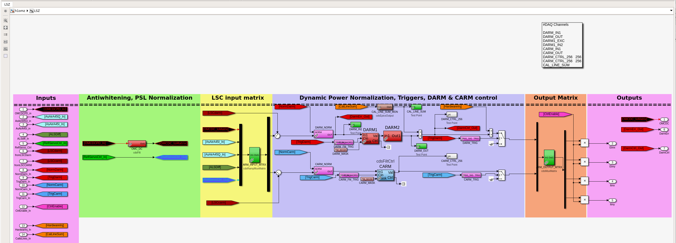
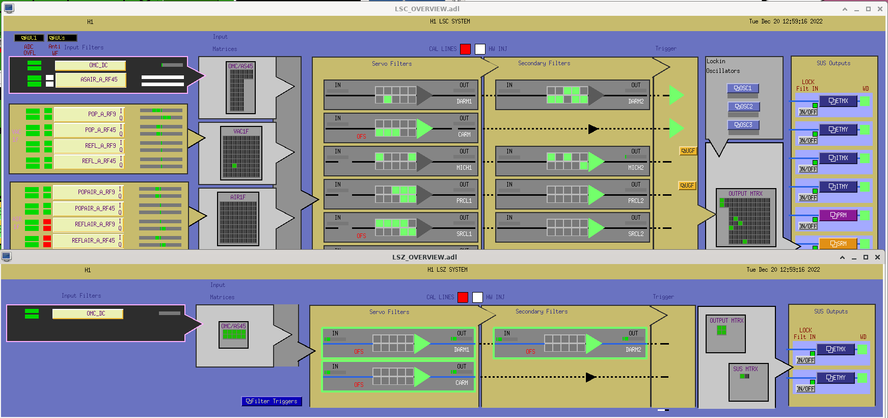
:: From either the sitemap > burnt orange OMC menu > LSZ, or on the above black IFO READOUT screen, one can get to all the nominal LSZ-DARM filters and matrices screen, shown in the Fourth attachment. Here, you'll see the differences are
. There's a lot less stuff on the LSZ screen, since this only takes in the 524 kHz version of the OMC DCPDs, filters via the LSZ-DARM1 and LSZ-DARM2 banks, to create LSZ-DARM control and sent out to the end stations. However, all this stuff is exact copies of the LSC DARM infrastructure.
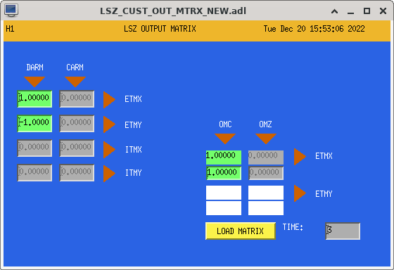
. The is also the new, extra output matrix at ETMX only, to be able to switch from the the nominal LSC DARM CTRL to this newly generated LSZ DARM_CTRL.
:: The new output matrix screen, as it stands now, is shown in the final, fifth attachment.
Just to close out, most of this OMZ and LSZ MEDM / EPICs infrastructure is exact copies of equivalent the OMC and LSC infrastructure, and Daniel's put in the hard work of filling out and copying over that infrastructure as needed.
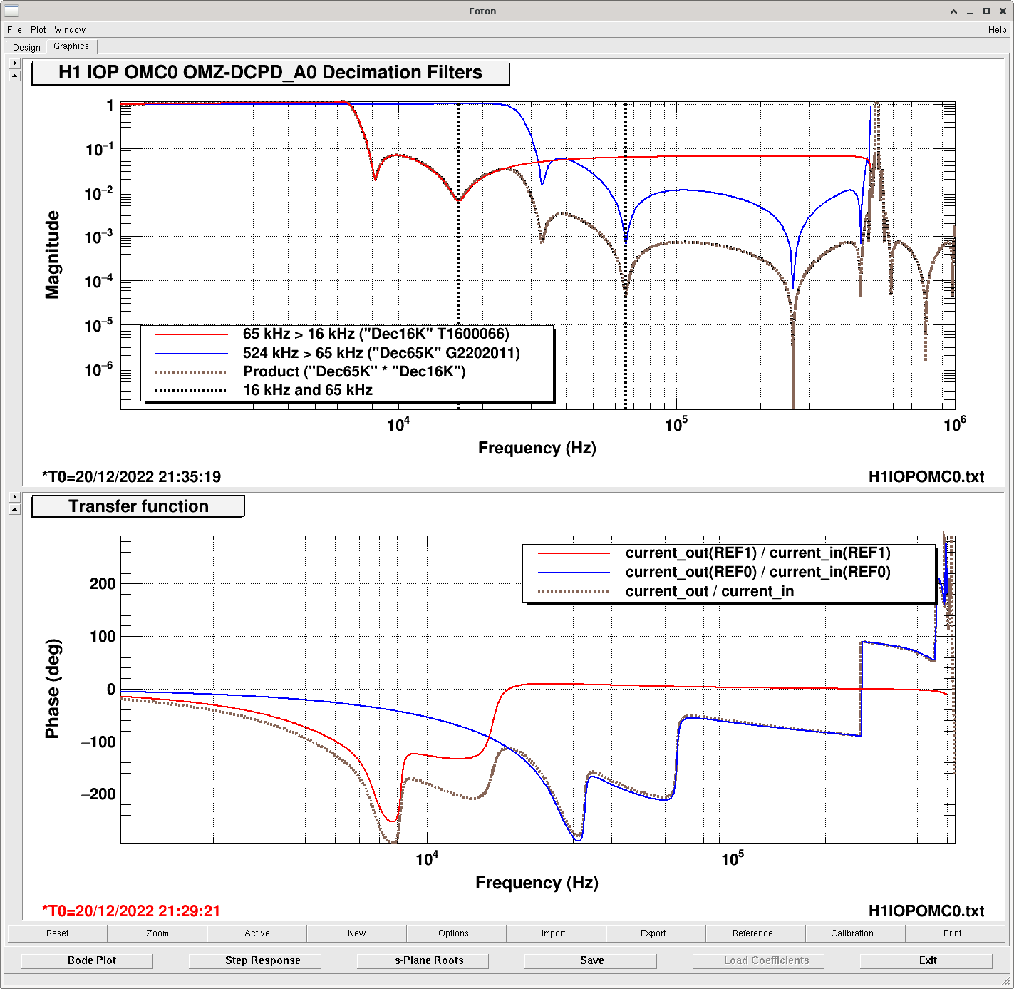
Since the OMZ-DCPD_A0 and OMZ-DCPD_B0 filter banks that live in the h1iopomc0 IOP model is the major part of infrastructure is really the only new part functionally,
In this comment, I cover the filter design used for the "4chn" filter module, and the "Dec65K" + "Dec16K" module

The first attachment shows the current configuration of the filter bank.

There, the new filter banks that *aren't* redundant with the 65k > 16k version in the OMC-DCPD_A and OMC-DCPD_B filter banks are
    - in FM1, "4chn", which is the divide-by-four gain to turn the sum of  the four analog copies of the DCPD_A channel into an average. The design string is simply "gain(0.25)".
    - in FM9, "Dec65K," this is the "first step" of the signal conditioning prior to decimation, or "IOP downsampling" filtering, to support the decimation from 524 kHz to 65 kHz. One can find the discussion of the design, and exact filter coefficients in G2202011.
    - in FM10, "Dec16K," this is the "second step" of the signal conditioning prior to decimation, to support the decimationfrom 65 kHz to 16 kHz. One can find the discussion of the design, and the exact filter coefficients in T1600066.

The second attachment shows the transfer functions of these filters, much like what is shown in G2202011, with the 16 kHz and 65 kHz sampling rates highlighted with the black dashed cursor, and total combined response of the two filters shown in brown dashed.

Passing on some institutional memory: as described in the simulink infrastructure discussion above in LHO:66489, the "524 kHz" signal in the h1iopomc0 IOP model, which (I think) is really running at 65 kHz, is shipped directly to the h1omz user model, running at 16 kHz, via shared memory IPC. A long time ago, the authors of the real-time code decided that
    - "if your signals are read in through the IOP, and the user model invokes an ADC part directly, typically at a lower rate, without IPC, then we'll use filters that are hard-coded into the real-time code to do the decimation pre-filtering for the user" BUT
    - "if you ship signals from the IOP model directly to the user model over IPC, without invoking an ADC part, to a model at a different sampling rate, then it's up the user to pre-condition the right decimation, up/down sampling, AA or AI filtering."
So, Daniel has explicitly chosen to have signal passed over IPC, such that the decimation filters are "user-definable," rather than what's been hard-coded in the RCG, because the latter is MUCH harder to change on the fly.
This is what Daniel means when he says "This also requires an explicit decimation filter that can be chosen appropriately."

For now, we've chosen as described above,
    (a) with "Dec16K" a copy of the hard-coded filter that the RCG uses for the 65 kHz to 16 kHz transition, T1600066
    (b) a new design for the 524 kHz to 65 kHz transition, G2202011.

But as the author of (b), I'm looking forward to characterizing the, > 7kHz low-frequency version of this system to see if my design works. I'm definitely open to changing it!
I'm especially concerned that the product of the two filters has essentially no suppression at the 524 kHz sampling rate.

Nominally, suppression at this would be taken care of with an *analog* anti-aliasing filter, but thus far the analog AA chassis is just a pass through, he installation of which is covered in LHO:66078, and what Daniel means when he says "There are no analog AA filters now" in the above main entry.
There is some design work in the works to *create* an appropriate analog filter, see ECR E2200456, but this will be ready only "just in time."