Kevin, Vicky
I've been working with Kevin on the full quantum noise budget for H1 using gwinc. Running this for Elenna's noise budget times from Wednesday at 76W (LHO:68869), this quantum noise budget is what I have so far, it still needs work. One takeaway so far is that - there is possibly some low-frequency quantum noise contribution to DARM above 40 Hz, but we need to be careful calculating the squeezing parameters to be sure. This is a work in progress. But, it would be interesting to understand if some of the low-frequency excess is really attributable to quantum noise, and if so what to do about it; I think reducing generated sqz levels will generally help us here. Another major reason to budget the quantum noise, is to understand in what ways we need to optimize, and how much squeezing we can still realistically optimize for.
One comment: this low frequency 40-100 Hz band is where quantum shot noise and radiation pressure noise are similar magnitude effects (frequency at which the "standard quantum limit" piles up). This is basically where FC was designed to operate at, and (I think) where a bunch of strange squeezer effects (like coherent misrotations), could thus really factor in. So, it'd be nice to accurately understand the full quantum noise calculation in this low frequency range, where DARM at higher power now sees excess mystery noise, to understand if it's related to squeezing. Below is how I (and I think generally, squeezers) am approaching the quantum noise budget.
1) Understand interferometer quantum noise without squeezing. Here's an example of gwinc's full quantum calcuation on no-squeeze data at 76W. Sheila has done this previously for 60W (LHO:67610) to understand IFO output losses. I'm following through her analysis now at 76W. One major takeaway at 60W, was that the interferometer losses may be high, for example ~10-25%. I second Sheila's recommendations, that we should better constrain our homodyne angle (aka measure the contrast defect) and SRCL detuning throughout thermalization, and optimize the optical gain in the IFO, to reduce/ understand IFO output losses better. And, we should try operating at higher DCPD currents like 30 mA to improve the readout angle for squeezing. At higher power, maybe we can also measure these two during thermalization. I believe the losses are still high when thermalized at 76W, most likely 15%, maybe up to even 30%. But, IFO output losses also seemed high (10-25%) before TCS tuning at 60W, so this could improve still. Our best squeezing at 60W, 4.5 dB, was observed after TCS optimizations to increase IFO optical gain and reduce high-freq laser noise. I think reducing IFO output losses and technical noise is our best path forward to observe / reveal more total DARM noise reduction from squeezing.
Budgeting IFO output losses -- from the squeezing loss wiki,
- ~8% IFO readout losses (IFO --> OMC: 1xOFI, OM1+3, OMC losses, DCPD QE).
- ~7% squeezer injection losses (SQZ --> IFO: 3xSFI, HAM7 losses, 1% pickoff to lock FC, 1xOFI).
- ~15% Expected squeezing losses total. (this limit could allow up to 6.5-7dB sqz.)
However, 4.5 dB squeezing corresponds to ~33% total loss (~15% mystery). 4 dB is about 37% total loss (~22% mystery). 6dB would be about 22% total loss (7% mystery). We are trying to understand the excess 15-25% mystery loss that limits observed squeezing. In part, wondering what is squeezer loss, and what is IFO output loss. The latter can be understood using the no-sqz spectrum.
With our squeezing observations of up to 4.5 dB (LHO:68251), we can constrain IFO readout losses as -- more than the known 8%, and likely less than < 25% for compatibility w/4dB sqz losses.
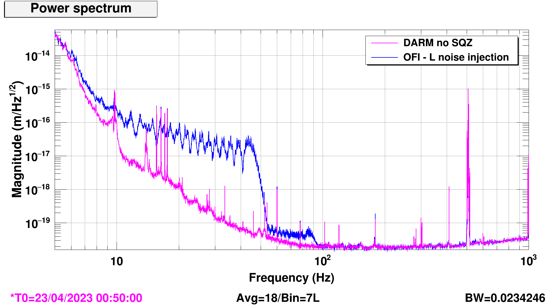
Looking at a no-sqz quiet time noise budget (GPS = 1366017765, span = 2400s), we can consider an arm power of 400kW, and readout losses of 20%. Higher arm powers (ASC_{X,Y}_CIRC_OUT reads ~430kW) will require more IFO readout losses to give our observed shot-noise-limited-displacement sensitivity -- that is, higher readout losses can explain the discrepancy between the circulating arm power and calibrated m/rtHz sensitivity of DARM, in the range where DARM quantum-noise-limited. Note: it seems LLO can operate with about 75% the circulating arm power, and yet reach almost similar shot-noise-limited displacement sensitivity, without squeezing. This suggests their IFO output losses are lower; if that is true, it would allow for higher observed squeezing levels, given similar squeezing-specific losses.
As external measurements of relevant IFO parameters, I'm considering the following for the noise budget:
- SRCL detuning around -0.2 deg. I'd guess it ranges between -0.1 to -0.4 degrees depending on thermalization, but this can be measured. I've been referencing Jeff's measurements of DARM sensing function vs. SRCL offset (LHO:67613) to interpret how the digital offset and DARM sensing function corresponds to physical parameters.
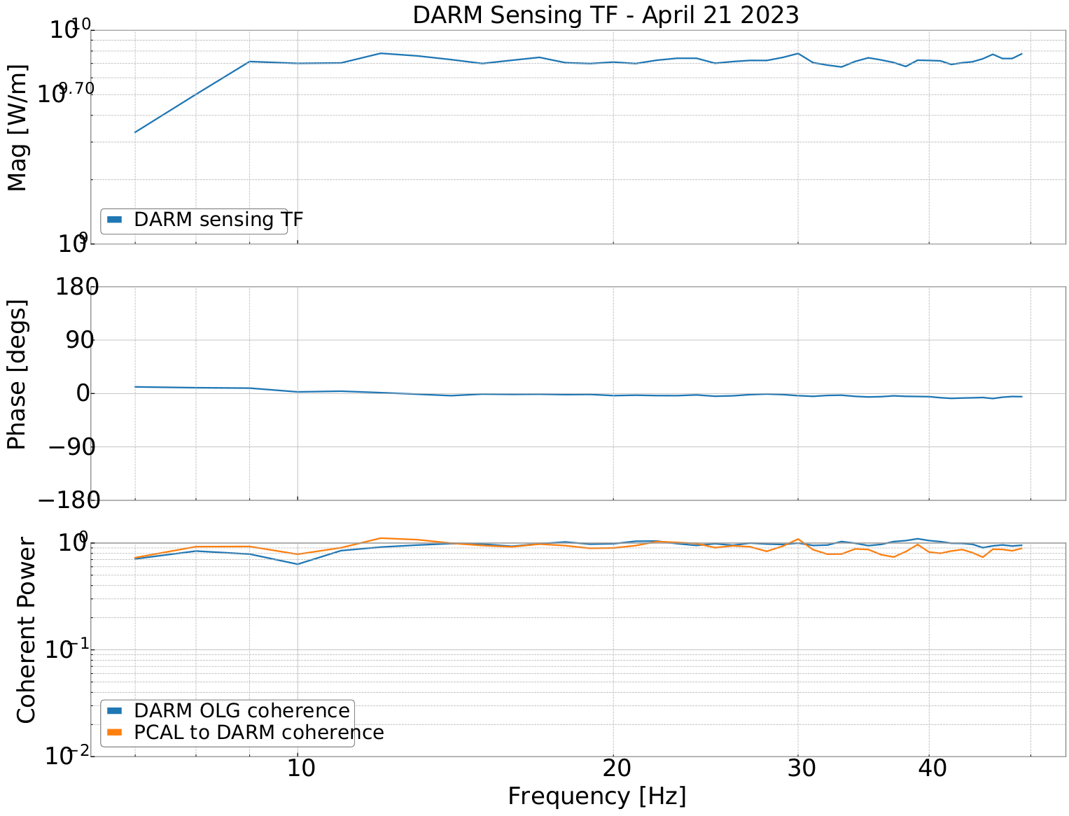
- Comparing Camilla's DARM sensing function from today, with Jeff's plots of H1 Sensing function vs. physical SRCL offsets, today's measurement looks like a SRCL detuning of about -0.35 deg early on in the lock (between orange and yellow).
- SRCL offset changes recently: After Jeff's measurements at 60W LHO:67613 on 2/24, the digital offset was set to -175. Recently on 4/10 at 78W, it was set to -165 to flatten the sensing function for calibration LHO:68554.
- IFO readout / homodyne angle = -17 degrees, from contrast defect measurement LHO:68859. Unsure if this changes with TCS tuning at noise budget time, or what it is now.
2) Now calculate the quantum noise with frequency-dependent squeezing. With this model of the IFO's ambient quantum noise without squeezing, we can now estimate the quantum noise with freq-dep squeezing, and begin to add it fully into the H1 noise budget. Full quantum noise calculation is more involved than the semiclassical quantum noise calculation typically calculated in the gwinc noise budget.
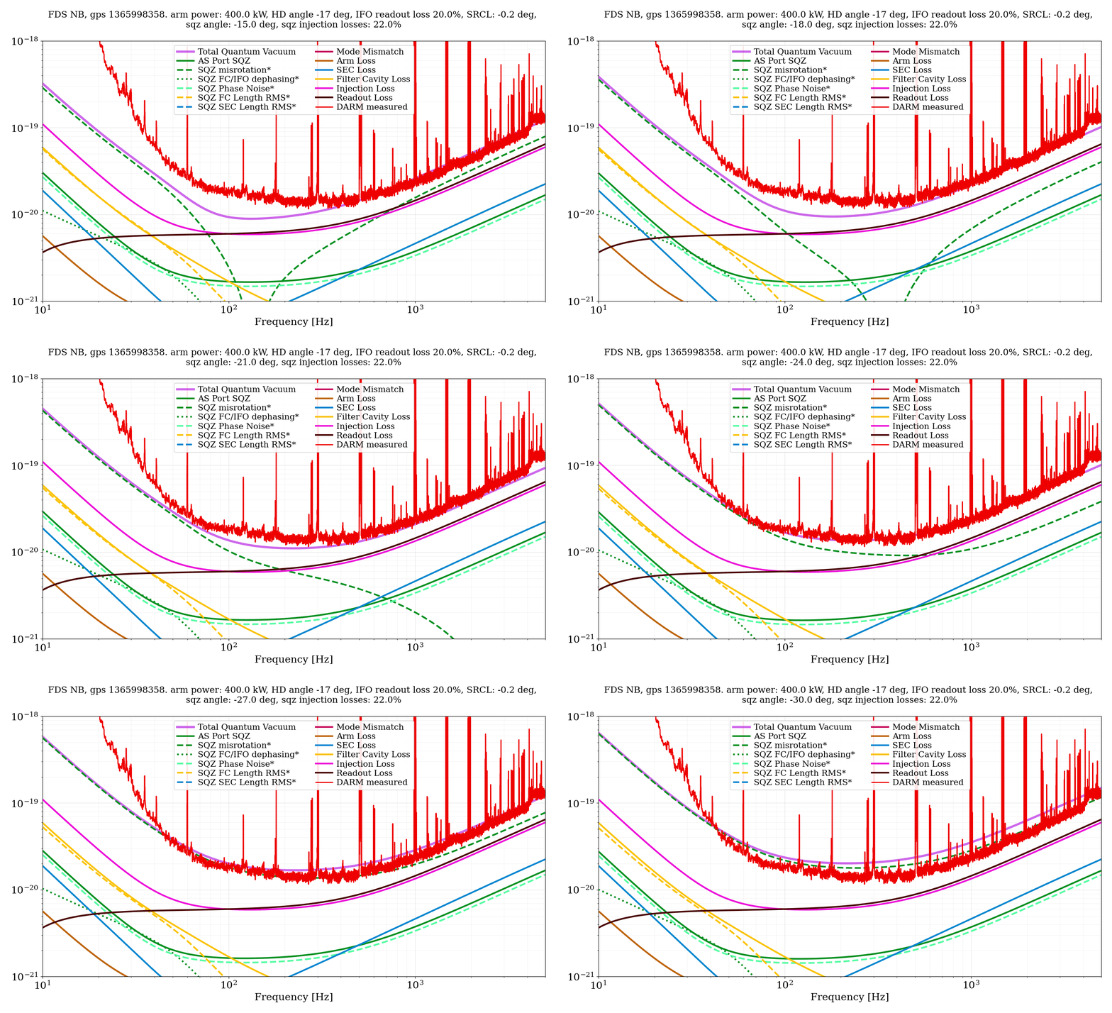
To summarize, for IFO parameters, I'm using 400kW, homodyne angle at -17 deg, SRCL @ -0.2 deg, and considering IFO readout losses of 20% (mid-range ish). For SQZ, I'm considering 16.5 dB generated sqz, FC detuning -35 Hz, and 15% excess sqz injection losses (for ~20% total). To start, injection losses are just broadband loss, ignoring all the complexity from coherent mode-matching interference, which can cause loss (~few %) and squeezing misrotations (~few degrees).
- After finding IFO no-sqz parameters that make sense, first we have to scan the squeeze angle to get to squeezing. This is a bit tedious/slow. For each IFO configuration, I made a squeeze angle .gif to see squeezing angles. I then sanity check whether the losses make sense, and choose the most likely squeezing angle. I then use this angle in the quantum noise budget, using gwinc to calculate quantum noise with FDS. I would like to fit / use mcmc to better estimate squeezing parameters eventually, but this is at least a start.
- By find "squeezing", I mean find the sqz angle which improves quantum noise near 100 Hz. In practice, this is where we've typically left the sqz angle (LHO:68814), to optimize quantum noise in the bucket. However, this the high-frequency squeeze angle to thermalize down with the SRCL detuning (it rotates ~15-20 deg in 1-2 hours). So, probably high-freq sqz will look wrong in the first 1-2 hours of thermalization, but it squeezing should always look good in the bucket from the start, and so the range shouldn't be too adversely impacted by this.
- Losses are somewhat degenerate between SQZ injection losses and IFO readout losses. I need to further understand how parameters are co-varied, and what we measure/do to tease things apart. But, it seems that with 15% readout losses, ~10-15% excess squeeze losses are compatible. With 20% readout losses, needs 5-10% sqz loss; with 25-30% readout losses, this could basically make up all of our sqz losses at 4.5 dB. I'm inclined to think the latter, higher IFO output loss case, is likely-- given that our squeezing levels have varied so much with simply IFO TCS / output loss optimizations.
- We expect to see laser (frequency) noise creep up as early as 1kHz, and start limiting darm above 4kHz, LHO:68737. It'd be great to look at laser-noise-subtracted squeezing levels.
- Whether or not it is quantum noise, this suggests operating with lower generated squeezing levels, maybe the minimum we need, could help if squeezing mis-rotations are hurting us at low frequencies. Generating too much squeezing is essentially asking for trouble in controlling the sqz angle through the bucket, given the amount of frequency-dependent rotations plausibly going on in the IFO.
Some thoughts on SQZ optimizations going into ER15.
Squeezer mode-matching and alignment: I don't think this is the biggest limiting effect on observed squeezing yet. I think we need to better understand the IFO output losses, given the serious circulating arm power vs. darm m/rtHz discrepancy. But, I do think with mode-matching and alignment, we can win a bit of squeezing if we check with classical noise (esp laser noise) subtraction. Overall, I think we've had conflicting observations on this front.
- We got 4.5 dB FDS after TCS tuning at 60W, LHO:68236. Getting more squeezing then was "easy", in the sense that it was not so sensitive to sqz alignment, psams, clf levels, generated sqz levels, etc. Then, our PSAMS were at ZM4/ZM5 = 120V/130V. I suspect what's happening is that, TCS tuning is reducing IFO losses (aka, increasing optical gain LHO:68177), and squeezing sees the same improved throughput. And in addition (maybe the same?), the readout angle got closer to 0, aka closer to optimal for squeezing.
- Getting >4dB of squeezing is also "easy" with the IFO cold at 2W, I think this has been consistently observed. For example, at 2W, Jan 18, 2023, LHO:66877, setting ZM4/5 = 110V/110V was better and we got up to 3.8 dB by moving PSAMS. In the same lock, when we powered up to 60W, the same PSAMS settings gave only 3.3 dB sqz. Since, whenever we inject squeezing at 2W, we can typically see over 4dB regardless of our PSAMS situation now. So, at 2W it seems lower PSAMS might've been more optimal. This all is compatible with a story that IFO output losses are low in the cold state, and thus squeezing losses are low, and thus there is more sqz.
- On the other hand, high PSAMS like 200/200 have consistently led to improved SQZ-OMC mode-matchings by metrics such as ADF transmission through the OMC (68665), or OMC mode scans of the squeezer seed beam (66946), which I think probe a similar mode-matching. We only use half the range of our PSAMS, between 100-200V; this range changes the ZM4/5 optics by ~100 uD according to the calibration (eg. H1:AWC-ZM{4,5}_PSAMS_DEFOCUS_MON_MDIOPTER). I wonder if, comparing to e.g. the ITM ROC changes measured by TCS for ITM deformation during thermalization, any interesting information exists here.
- The problem is, it's hard to know our IFO or OMC mode-matching at full lock, with a thermalized IFO, since there are limited in-situ diagnostics available. The ADF should be able to help us diagnose mode matching and alignment. Even for squeeze (mis)-rotation, the ADF would be helpful, but we need to re-do ADF calibration after all TCS tuning on a later Tuesday, to start running sweeps again.
- Further, our diagnostics and SQZ-IFO ASC (based on AS42 = IFO's RF45 xx SQZ RF3) are both run using squeezer sidebands, which could possibly be misaligned from the main IFO squeezed light. We've observed (e.g. by walking OMC ASC QPD offsets 67994, or walking SQZ ASC offsets 66756), that our SQZ ASC may not bring us to the most optimal alignment, but at least close; LLO:64458 has now observed similar offsets, possibly due to the different sqz-sideband alignments, are needed to fully optimize squeezer alignment.
If the IFO TCS tuning can further optimize optical gain (aka reduce IFO output losses) and reduce laser noise, continuing on from LHO:68875, that would of course be great all around. Once IFO alignment changes / settles, we can re-zero our AS42 offsets, and begin optimizing the SQZ-ASC alignment offsets, and maybe double-check / walk OMC alignment offsets again as Koji did in LHO:67994, again looking to optimize IFO optical gain. In practice, we should probably operate with less generated squeezing than we use now. Additionally, if we can understand /mitigate the issue with higher CLF powers, running with more CLF power should help us in all ways, for example it'd give us more robust ASC alignment signals. Perhaps we can also explore the higher DCPD current (~30mA) as well, and see if the a better readout angle helps for squeezing.
Summary: going into ER, the SQZ automation with ISC_LOCK seems reasonably robust, and we will continue to work through edge cases. At this circulating arm power, we've so far observed up to 4dB FDS LHO:68701, which has been able to give us 20-25 Mpc in range. In ER, with a more settled IFO thermal state and alignment, and with more quiet time for SQZ optimization, we should be able to take on more serious squeezer optimizations, especially focusing on SQZ + IFO optimizations for increasing range. I hope that working through the full quantum gwinc noise budget can help us understand how to make these DARM range optimizations, and that doing these IFO and SQZ optimizations can bring it back up to at least the 4.5 dB noise reduction w/FDS we saw once at lower power, LHO:68251.