Displaying reports 20901-20920 of 87770.Go to page Start 1042 1043 1044 1045 1046 1047 1048 1049 1050 End
Reports until 08:49, Friday 21 April 2023
H1 PSL
ryan.short@LIGO.ORG - posted 08:49, Friday 21 April 2023 (68888)
PSL Status Report - Weekly

FAMIS 21436


Laser Status:
    NPRO output power is 1.822W (nominal ~2W)
    AMP1 output power is 68.88W (nominal ~70W)
    AMP2 output power is 143.4W (nominal ~140W)
    NPRO watchdog is GREEN
    AMP1 watchdog is GREEN
    AMP2 watchdog is GREEN

PMC:
    It has been locked 0 days, 22 hr 54 minutes
    Reflected power = 20.09W
    Transmitted power = 105.2W
    PowerSum = 125.3W

FSS:
    It has been locked for 0 days 4 hr and 12 min
    TPD[V] = 0.949V

ISS:
    The diffracted power is around 2.1%
    Last saturation event was 0 days 4 hours and 10 minutes ago


Possible Issues:
    PMC reflected power is high (still need to tweak mode matching at some point)

LHO General
ryan.short@LIGO.ORG - posted 08:09, Friday 21 April 2023 - last comment - 10:21, Friday 21 April 2023(68887)
Ops Day Shift Start

TITLE: 04/21 Day Shift: 15:00-23:00 UTC (08:00-16:00 PST), all times posted in UTC
STATE of H1: Commissioning
CURRENT ENVIRONMENT:
    SEI_ENV state: CALM
    Wind: 7mph Gusts, 4mph 5min avg
    Primary useism: 0.02 μm/s
    Secondary useism: 0.22 μm/s
QUICK SUMMARY: H1 has been locked for 2.5 hours at NLN. We are running with BRSY on this morning during wind fence work to test Jim's new ISI filter. At the next lockloss, there are plans for a slow controls power supply swap and SRM drive measurement.

Comments related to this report
camilla.compton@LIGO.ORG - 10:21, Friday 21 April 2023 (68895)SEI

The 1366111098 04:18am PDT lockloss was caused by a small (<1000 on PEAKMON) earthquake, see attached.

Images attached to this comment
H1 ISC
daniel.brown@LIGO.ORG - posted 07:49, Friday 21 April 2023 (68886)
Switched off LSC lines

Elenna, Dan

We decided to remove the PRCL and SRCL lines being injected at 245.1 and 253.1 Hz for now as we don't need to be tracking them all the time.

The lines were commented out from from DRMI_TO_POP in ISC_LOCK

        #ezca.switch('LSC-PRCL2', 'FM5', 'ON')
        #ezca.switch('LSC-MICH2', 'FM5', 'ON')
        #ezca.switch('LSC-SRCL2', 'FM5', 'ON')
        #ezca['LSC-OUTPUT_MTRX_5_7'] = 1 
        #ezca['LSC-OUTPUT_MTRX_6_9'] = 1
        #ezca['LSC-LOCKIN_1_OSC_CLKGAIN'] = 500
        #ezca['LSC-LOCKIN_3_OSC_CLKGAIN'] = 500

H1 TCS
daniel.brown@LIGO.ORG - posted 05:55, Friday 21 April 2023 - last comment - 06:09, Friday 21 April 2023(68884)
SR3 heater pulse

I have pulsed the SR3 at 2W for 10 minutes starting at 1366116331 with the AWG lines on.

The idea is to see how large an effect this size of pulse makes. I started this just after we powered up so if it causes a lockloss then it will have cooled down and re-locked for when people come in.

A similar pulse for the ITM ring heaters makes a ~2 hour transient and shows how various buildups change. If this size pulse is ok we can try it again when fully thermalised at some point, but maybe it'll need to be bigger, unsure.
 

Comments related to this report
aidan.brooks@LIGO.ORG - 06:09, Friday 21 April 2023 (68885)TCS

For reference, the step-functions response of the SR3 heater was measured here: LLO aLOG 27262. The time constant, tau, is approximately 70 minutes (based upon reading off the time it takes to reach 70% of the steady-state value).

H1 OpsInfo (DetChar, ISC)
jeffrey.kissel@LIGO.ORG - posted 23:13, Thursday 20 April 2023 (68883)
IFO_UNDISTURBED Gaurdian Flipped to UNDISTURBED
J. Kissel

I've lost track if we're still using the UNDISTURBED guardian to Mark that no one's messing with the detector right now (or at least there's no one in the control room, there may be full conversations on Mattermost that I'm missing...), but I figure it's worth letting folks getting ready for ER15 that there's nothing going on and this would be a good time to do passive DetChar studies. 

I flipped the state at 2023-04-21 06:07 UTC (23:07 PDT), but no one's touch the IFO since probably Apr 21 2023 02:48:00 UTC (19:48 PDT) when Eleonora and Xinghui were done for the day.

Oh, and I nudged the DIFF_OFFSET a little when the verbal alarm complained that IR was not found, but other than that, the IFO got NOMINAL LOW NOISE entirely by itself. 

Headed home for the night.
H1 CAL (CAL, CDS, ISC)
jeffrey.kissel@LIGO.ORG - posted 22:16, Thursday 20 April 2023 - last comment - 14:50, Friday 21 April 2023(68880)
Debugging TDCFs: Mysteries with the PCAL Line DEMOD Phase vs. 16 kHz Clock-cycles from IPC Delays SOLVED
J. Betzwieser, L. Dartez, E. Goetz, J. Kissel

We've circled the wagons to try to understand why we're consistently getting things wrong when we try to update the "reference model DARM Loop transfer function values at calibration frequencies" (aka what the calibration group typically refers to as simply "EPICs Records") and get time-dependent correction factors (TDCFs) to the IFO's sensing and actuation functions that are *very* inconsistent with MCMC fit values for corresponding parameters (overall gain of the sensing function [often loosely referred to as the "optical gain"], coupled cavity pole frequency, and the actuation strengths for each of the three ETMX actuator stages). Namely, yesterday's attempt by Louis, LHO:68856 convinced us that we've fundamentally forgotten about *something* between O3 and O4, and it's manifested in how the latest version of pyDARM is written.

While we can't say that we've solved *all* of the issues, we have found and remembered the *a* major thing, and it has to do with the differences between how GDS calculates TDCFs and CAL-CS calculates TDCFs, and our valiant efforts to change the infrastructure for for O4, such that both are doing the same thing. 

Here's the fundamentals of the TDCFs:
    (A) In order to determine things like the (relative) optical gain, cavity pole, we always need to find the transfer function between of DARM_ERR and PCAL, i.e. DARM_ERR / PCAL.

    (B) Both GDS and CAL-CS use demodulation techniques to find this transfer function, taking some version of the in-loop signals, DARM_ERR|_OMC and PCAL|_END, band-passing them, and beating them against a "local" oscillator to find I and Q, or real, and imaginary components of those demodulated signals, and then taking the coherent, complex ratio of the two sets to form the transfer function.

    (C) Both pipeline use the same reference model transfer function values (EPICs records) to divide out known stuff about the electronics, suspension dynamics, etc.

    (D) Both pipelins use the CAL-CS copy of the in-loop DARM_ERR signal, DARM_ERR|_CS. This signal is delayed by one 16 kHz clock cycle, exp(-1i*phi) as its shipped over inter-process communication from the OMC model to the CAL-CS model,
        DARM_ERR|_CS  = DARM_ERR|_OMC * exp(-1i*phi)        (1)
           or
        DARM_ERR|_OMC = DARM_ERR|_CS  * exp(+1i*phi)        (2)

    (E) There's been a constant point of confusion (discrepancy, or loss of institutional memory) that CAL-CS reads PCAL from corner station, PCAL|_CS, where GDS reads PCAL from the end-station, PCAL|_END,
        PCAL|_CS  = PCAL|_END * exp(-1i*phi)                (3)
           or 
        PCAL|_END = PCAL|_CS * exp(+1i*phi)                 (4)

    and reconciling that between the two pipelines. In the O2-O3 era, we *thought* we reconciled the discrepancy by modifying the CAL-CS pipeline's PCAL demod phase, adding a negative phase that corresponded to the value (phase) of a one 16 kHz clock cycle delay at each calibration line frequency,
        phase = 180/pi*angle(exp(-1i*2*pi*linefreq*(1/16384 Hz)))
      You can see this adjustment every time we've had to mode a PCAL calibration line frequency, and enter in a new phase value LHO:48534, LHO:44005, LHO:31748, etc. 

    (F) In April 19 2019, when we got bit one last time by this loss of institutional memory, and we vowed to "fix all this" and demand that "every part of both the GDS and CAL-CS pipeline should ingest the same thing, and compute the same thing, and use the same EPICs records" -- see IIET Ticket 12638, pydarm issue #17.

    (G) Between the end of O3 and now (yes, for 3 years), Evan's been championing a new version of pyDARM, and among many other improvements, we'd that hoped to resolve the issues with the computation of the EPICs records. In the last couple of attempts to "push" those EPICs records (LHO:68856), as well as attempts to move TDCF calibration line frequencies LHO:66268, the resulting TDCFs were wildly different from the MCMC fit values that we expect -- most typically in the optical gain, kappa_C, and the coupled cavity pole frequency, f_cc.
    
    (H) In July 2022 (LHO:64005), I added a channel to the frames, H1:CAL-DELTAL_REF_PCAL_DQ, which is a corner station copy of which ever PCAL we're using as our reference, i.e. PCAL|_CS -- such that the GDS pipeline *could* switch over to using the this version of the PCAL.

Now you're caught up with yesterday, when Louis and I sent out the bat signal to circle the wagons.

After comparing old EPICs records (not updated since O3) against new EPICs records (recently computed by modern pyDARM and a modern pyDARM model parameter set), 
CLUE 1: Joe found that the *newly* computed reference model transfer function value for the so-called "PCAL Corrections" for the 410.3 showed a difference, only in phase, of 18.03 deg against the old values. It smelled suspiciously like double the phase delay expected to be put in the DEMOD PHASE, 9.02 deg,
    180/pi*angle(exp(-1i*2*pi*410.3*(1/16384))) = -9.0154,
    180/pi*angle(exp(-1i*2*pi*410.3*(2/16384))) = -18.031
Suspicious that we were double counting this delay, we went back to the O3 code that computed the PCAL corrections.

Remember, PCAL corrections are the offline corrections one needs to perform on any copy of any PCAL RX or TX PD channel in true DARM displacement caused by PCAL, DELTAL_PCAL, which includes the stuff that the front-end doesn't do to the channel before storage,
    * arm sign                  # a conversion of pcal force (which is in the minus 
                                # longitudinal direction, in test mass suspension 
                                # euler basis) to DARM force (PCALY makes negative 
                                # DARM, PCALX makes positive DARM)              

    * 1/f^2                            # the "rest" of the TST-stage force to TST-stage 
                                       # displacement transfer function, which *acts* 
                                       # like a "dewhitening" filter

    * 1 / (analog AA)                         # high frequency inversion of the response 
                                              # of the 65 kHz analog AA filter for any 
                                              # readback signal

    * 1 / (digital 65 kHz to 16 kHz delay)    # high frequency inversion of the response 
                                              # of the 65 kHz to 16 kHz downsampling filter
But also, critically, where the copy of the pcal signal is used -- the corner station or end-station -- the pcal correction must also either include or exclude the exp(-1i*phi) clock cycle delay, as defined above in Eqs. (3) and (4).

The new pydarm code (as of git hash 20668eb4), has a method that produces this correction, compute_pcal_correction. Importantly, in that version, it has a boolean flag, where the user of the method can determine whether the user is correcting a PCAL|_CS or a PCAL|_END channel. When "endstation=False," then it's to be used for a cornerstation copy of the PCAL, PCAL|_CS, and it divides by one 16 kHz clock-cycle delay, which would create the equivalent of equation (4) from above, 

    (pcal_sign *
     pcal_dewhitening /                 
    (pcal_analog_aa_hi_f * pcal_digital_aa) /
     end_to_calcs_response)

where end_to_calcs_response is either a transfer function of 1 (when endstation=True), or a one 16 kHz clock-cycle delay (when endstation=False).

Stumped, because this makes sense to us, we went to old O3 codesensing.py, line 215,

    pcalCorrection = signal.freqresp(pcaldewhitening, 2.0*np.pi*freq)[1] /              # 1/f^2
                     ( signal.freqresp(AAanalog, 2.0*np.pi*freq)[1] *                   # 1/(analog AA)
                     AAanalog_delay/abs(signal.freqresp(AAanalog, 2.0*np.pi*0.01)[1])   # (Some crap to fix a bad model of the analog AA)
                     * totalSensingDigital_freqresp                                     # 1/(digital AA)  
                     * omcDelay_freqresp )                                              # A poorly named variable that resolves to a TF of 1 

CLUE #2: we find that O3's pcal correction did not contain any advance or delay. We collectively recall: this variable was designed to be the correction to PCAL|_END channels, and did not consider the possibility of a corner station PCAL|_CS channels. 

So "how did it all ever even work??" that drove us to the O3 code that made the EPICs record itself, which *used* pcalCorrection, in , lines 431 - 434 

    EP9 = pars.Cpars.pcal.Pcal2DARMactSign *                   # arm sign
          sensProd.pcalCorrection[4] *                         # (1/f^2)*(1/analog AA)*(1/digital AA)
          np.exp(-2.0 * np.pi * 1j * freq[4] * 1/16384.0)      # exp(-1i*phi)

which reveals ... there's a delay in here! But ... GDS computes its TDCFs from PCAL|_END channels, so it doesn't need Eqs. (3) and (4) and shouldn't need any delay. And yet, both CAL-CS and GDS use this same EPICs record to compute TDCFs... CLUE #3: OH YEAH Eqs. (1) and (2) -- this so-called "PCAL_CORRECTION" EP9 (and their equivalent EPs at other frequencies) isn't actually *just* correcting PCAL, it's a correction to the DARM_ERR|_CS / PCAL|_END transfer function, because GDS reads in DARM|_CS, not DARM|_OMC, and thus needs Eq. (2).

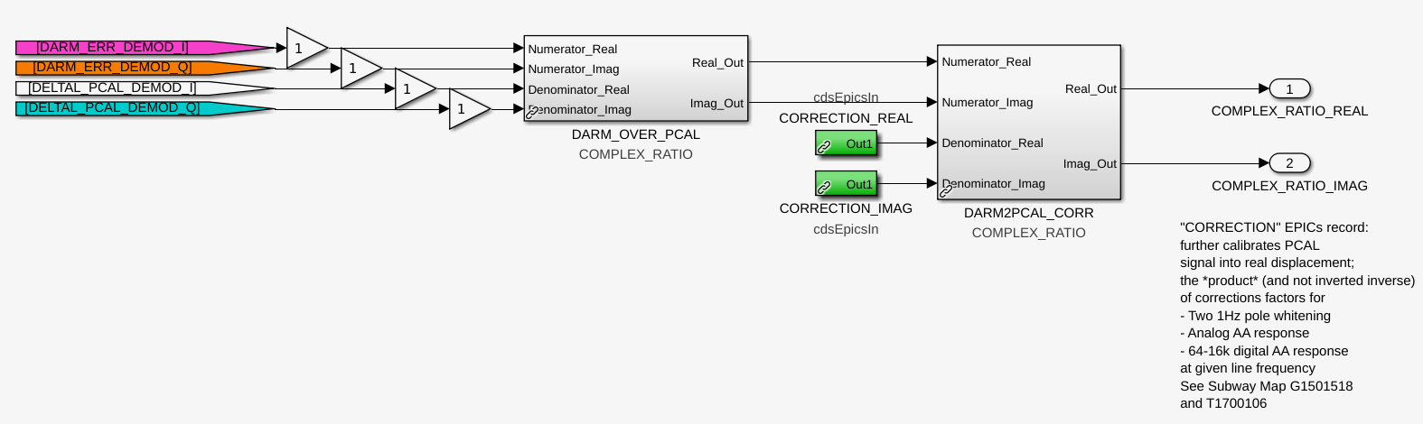
This drove us to remind ourselves how these EPICs records are actually applied in the front-end code. the first attachment shows that it gets even nastier because CLUE #4: the "PCAL corrections" EP9 (and the like), are *divided* into the DARM|_CS / PCAL|_CS transfer function.

If you're not pulling our hair out already by this point, don't worry, Joe, Evan, Louis, and I have *definitely* pulled out enough hair today already for you. 

This means that this is the math that's happening in the GDS algorithm,

    DARM_ERR|_CS      1        DARM_ERR|_CS                                     1
    ------------  *  ---   =   ------------  * --------------------------------------------------------------------
     PCAL|_END       EP9         PCAL|_END     (arm sign) * (1/f^2) * (1/analog AA) * (1/digital AA) * exp(-1i*phi)
                               
                               DARM_ERR|_CS                         exp(+1i*phi)
                           =   ------------  * -----------------------------------------------------
                                 PCAL|_END     (arm sign) * (1/f^2) * (1/analog AA) * (1/digital AA)
                               
                                                DARM_ERR|_CS * exp(+1i*phi)
                           =   -----------------------------------------------------------------
                                 PCAL|_END * (arm sign) * (1/f^2) * (1/analog AA) * (1/digital AA)

                               DARM_ERR|_OMC
                           =  ---------------
                               DELTAL_PCAL

And in order for the CAL-CS pipeline to use the same EPICs record and produce the same answer -- but with the PCAL|_CS -- CAL CS has to install a "fudge" by altering the phase of the PCAL DEMOD, i.e. in the denominator channel before the transfer function is taken, CLUE #5: but that DEMOD phase has the opposite sign than you expect:

    DARM_ERR|_CS             1              1        DARM_ERR|_CS                                             1
    ------------ * -------------------- *  ---   =   ------------  * ------------------------------------------------------------------------------------------
     PCAL|_CS      (DEMOD exp(-1i*phi))    EP9         PCAL|_CS     (arm sign) * (1/f^2) * (1/analog AA) * (1/digital AA) * exp(-1i*phi) * (DEMOD exp(-1i*phi))
                               
                                                     DARM_ERR|_CS * exp(+1i*phi)                              1                    
                                                 =   -----------------------------   * -----------------------------------------------------
                                                     PCAL|_CS  (DEMOD exp(-1i*phi))   (arm sign) * (1/f^2) * (1/analog AA) * (1/digital AA)

                                     THE DENOMINATOR ONLY BECOMES PCAL|_END IF (DEMOD exp(-1i*phi)) == exp(+1i*phi)
                               
                                                                            DARM_ERR|_OMC 
                                                 =   -----------------------------------------------------------------
                                                     PCAL|_END * (arm sign) * (1/f^2) * (1/analog AA) * (1/digital AA)

                                                    DARM_ERR|_OMC
                                                 =  -------------
                                                     DELTAL_PCAL

So in in the most convoluted way, with delays turning into advances by a series of confusing divisions across disparate code, front-end models, and hacks on hacks, and a confusing convention with the front end's DEMOD phase system, somehow it all ended up working in O3.
Also notice, that if one computes the transfer function with both channels in the CAL-CS model, then both experience a one 16 kHz clock cycle delay, and the delays, or advances cancel, and it's like you're reading in the channels from their original location,

    DARM_ERR|_CS      DARM_ERR|_CS    exp(+1i*phi)     DARM_ERR|_OMC
    ------------   =  ------------ *  -----------   =  -------------
      PCAL|_CS          PCAL|_CS      exp(+1i*phi)        PCAL|_END

This fact was exploited a few times early on when folks first were debating who should have what delay when and how, and we ended up confusing ourselves by not including explicitly including advances or delays at all.

So, let's now zoom forward back again to O4, where we've got new code from Evan, where he's pre-included the option to envoke computer_pcal_correction with either the endstation set to True (no delay/advance) or False (dividing by a delay exp(-1i*phi), or equivalently multiplying by an advance exp(+1i*phi)).

How is the EPICs record computed? Now we head to the compute_epics_records in the calcs.py module (last changed at git hash version 60d261c4), to find CLUE #6: there's an error in this code, in that it does not apply the extra exp(-1i*phi) delay here:
        PCAL_LINE2_CORRECTION = pcal_correction[4]          # used to be EP9 from above

and for brevity we'll call this version "CORR".

On top of *this* CLUE #7: Louis and I removed the CAL-CS fudge delay yesterday, thinking "Oh, well, every pipeline is computing the DARM / PCAL transfer function ratio with the 'fixed' EPICs records with endstation set to False, so we shouldn't need the DEMOD phase fudge.

That means the CAL-CS pipeline as of yesterday instead has been computing

    DARM_ERR|_CS          1           1        DARM_ERR|_CS                            (DEMOD exp(0))
    ------------ * ------------- *  ----   =   ------------  * --------------------------------------------------------------------
      PCAL|_CS     (DEMOD exp(0))   CORR         PCAL|_CS      (arm sign) * (1/f^2) * (1/analog AA) * (1/digital AA) * exp(+1i*phi)
                               
                                               DARM_ERR|_CS * (DEMOD exp(0))                               1
                                           =   -----------------------------    * -----------------------------------------------------
                                                  PCAL|_CS * exp(+1i*phi)         (arm sign) * (1/f^2) * (1/analog AA) * (1/digital AA)
                               
                                             DARM_ERR|_CS                              1
                                         =   ------------ * ---------------------------------------------------
                                               PCAL|_END    (arm sign) * (1/f^2) * (1/analog AA) * (1/digital AA)

                                             DARM_ERR|_CS
                                         =   ------------ 
                                             DELTAL_PCAL

                                              DARM_ERR|_OMC
                           (DOES NOT EQUAL)  ---------------
                                               DELTAL_PCAL

Where one can see that, when one sets endstation to False, and you don't include any fudge phase in the PCAL DEMOD, there's a now missing advance that propagates the CAL-CS copy of DARM_ERR|_CS back to DARM_ERR|_OMC, and this messes up all computation of TDCFs that involve PCAL, which y'know is ALL of them. We see it manifest the most on the 410.3 Hz line, and thus in the calculation of the (relative) optical gain kappa_C and coupled cavity pole frequency, 180/pi*angle(exp(-1i*2*pi*(410.3 Hz/16384 Hz)) = -9.015 is MUCH larger than the 17.1 Hz line's phase modifier of 180/pi*angle(exp(-1i*2*pi*(17.1 Hz/16384 Hz)) = -0.3757.

This also explains why, when we compare EP9 with one delay, against CORR with one advance, we see a 2x abs(9.015) = 18.031 deg change.

By this point, Evan, Joe, Louis, and I all agree -- because the transfer function (DARM_ERR|_CS / PCAL|_CS) * (1/CORR) is missing an advance to propagate DARM_ERR from CAL-CS back to the OMC, or DARM_ERR|_CS * exp(+1i*phi) = DARM_ERR|_OMC, Eq. (2) from above, we can either
    (i) Fudge the phase of DARM_ERR DEMOD with +9.015, to create the missing advance, or
    (ii) Continue with the hot mess of convolution and fudge the phase of the PCAL DEMOD with -9.015

and in the mean time, Evan will edit O4-era pyDARM to include a darm_advance in the computation of CORR, and rename the EPICS record variable to be something like DARM_OVER_PCAL_CORR or something.

%%%%%%%%%%%%%%%%%%%%%%%%%%%%%%%

OK, all of the above was all the whiteboard math and history, but as we all know -- you can math 'til your blue in the face, but when it comes to minus signs, multipications vs. divisions, or delays vs. advances -- you've got a 50/50 shot, and the interferometer will tell you very quickly if you've got it right.

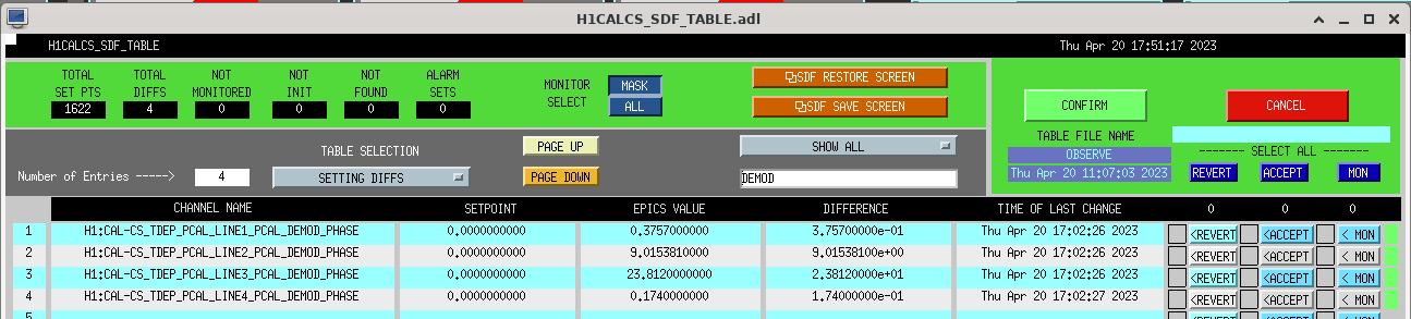
So, as a quick test, Louis and I went with option (ii), ignored CLUE #5 'cause "who would believe that??," and installed the "appropriate" DEMOD phase fudges, exp(-1i*phi), in all the PCAL line DEMOD phases.

    PCAL line
    Frequency (Hz)    Demod Phase Channel                           Phase (deg)
    7.93              H1:CAL-CS_TDEP_PCAL_LINE4_PCAL_DEMOD_PHASE    -0.174
    17.1              H1:CAL-CS_TDEP_PCAL_LINE1_PCAL_DEMOD_PHASE    -0.3757
    401.3             H1:CAL-CS_TDEP_PCAL_LINE2_PCAL_DEMOD_PHASE    -9.01538
    1083.7            H1:CAL-CS_TDEP_PCAL_LINE3_PCAL_DEMOD_PHASE    -23.812

THE IFO LAUGHED AT US, SAYING "HA! YOU FORGOT ABOUT CLUE #5!"

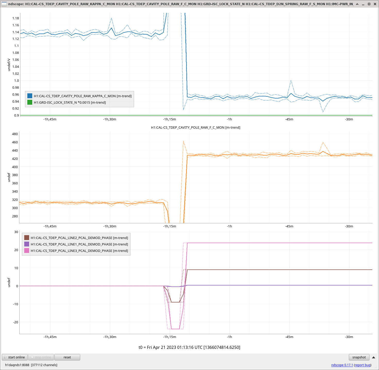
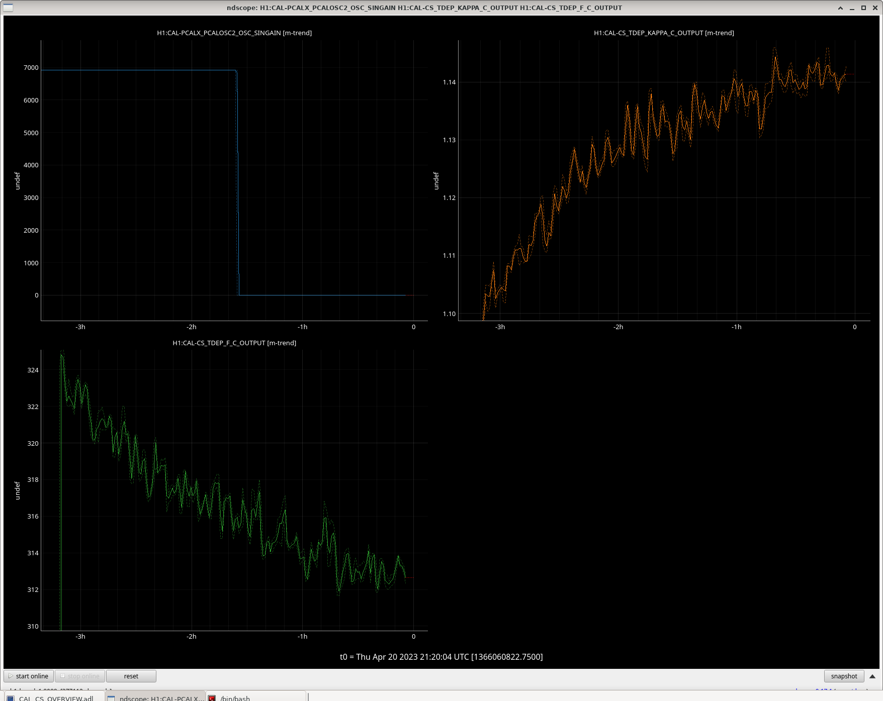
See Second attachment.
With a brief moment in time that we installed these negative phase rotations, the already nonsensical ~310 Hz coupled cavity pole frequency and 1.12 relative optical gain shot to ...let's just say "off the map bad.
So, we installed positive phase fudges...

    Frequency (Hz)    Demod Phase Channel                           Phase (deg)
    7.93              H1:CAL-CS_TDEP_PCAL_LINE4_PCAL_DEMOD_PHASE    +0.174
    17.1              H1:CAL-CS_TDEP_PCAL_LINE1_PCAL_DEMOD_PHASE    +0.3757
    401.3             H1:CAL-CS_TDEP_PCAL_LINE2_PCAL_DEMOD_PHASE    +9.01538
    1083.7            H1:CAL-CS_TDEP_PCAL_LINE3_PCAL_DEMOD_PHASE    +23.812

and the cavity pole frequency and optical gain settled on a MUCH more reasonable 430 Hz, and (relative) optical gain of 0.95!

The cavity pole is consistent with the MCMC fits to the swept sine measurements and the change in optical gain is totally reasonable because we're *still* changing alignment and TCS settings.


WE FIGURED IT OUT, TEAM. WE DID IT.
We can trust the answers from front-end, CAL-CS computed TDCFs again...
and
There's something that doesn't make sense about the phase convention for the standard CDS DEMOD part, but we can figure that out later.
Images attached to this report
Comments related to this report
joseph.betzwieser@LIGO.ORG - 14:50, Friday 21 April 2023 (68902)
So looking at the cdsPhase part, it uses a rotation matrix of:
[I']      [ cos(phi)  sin(phi)]  [I]
      =                        *
[Q']      [-sin(phi)  cos(phi)]  [Q] 
        

This corresponds to a rotation clockwise in phi, with phi > 0.  Normally

You can imagine this matrix as multiplying the input I + 1i*Q vector by exp(-1i*phi) = cos(phi) - 1i*sin(phi).
Or explicitly, the I' + 1i*Q', the I and Q after rotation or after multiplication by this delay, are:

I' =  I*cos(phi) + Q*sin(phi)
Q' = Q*cos(phi) - I*sin(phi)

So to apply the delay Jeff needed, we need to use a positive phi into the cdsPhase rotation part.

Just as further documentation, I note GDS and the front end are multiplying by exp(-1i*wt), where w is the LO frequency, which means in all cases, for increasing time, phase rotates clockwise.  So we all have this same choice of handed-ness, which also matches what pydarm expects.


H1 SUS (AOS, ISC)
jeffrey.kissel@LIGO.ORG - posted 19:48, Thursday 20 April 2023 (68881)
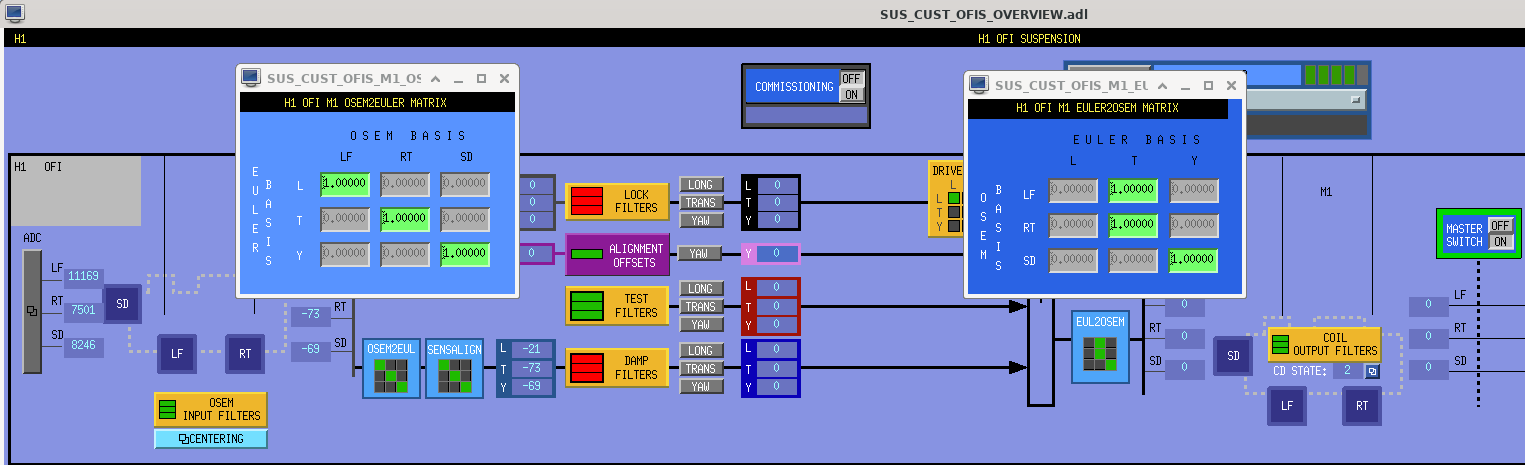
OFI OSEM2EUL sensing and EUL2OSEM drive matrices left in Diagnostic Configuration
J. Kissel, for E. Polini and X. Yin

Eleonora and Xinghui let me know that they're leaving the OFI OSEM2EUL sensing and EUL2OSEM drive matrices left in diagnostic configuration configuration for the time being while they continue their efforts to diagonalize the undiagonalizable OFI suspension / OSEMs. 

This is fine, because we've turned off all control to the OFI (damping loops) anyways, and there's otherwise drive request, so this does not impact the IFO at all. 
They promise to pick up where they left off tomorrow morning.
Images attached to this report
H1 CDS
david.barker@LIGO.ORG - posted 16:39, Thursday 20 April 2023 (68879)
Pulizzi power control unit EPICS IOC moved from h1fescript0 to cdsioc0

The three pulizzi IOC processes, which were running in tmux sessions on h1fescript0, are now running at their permanent location on cdsioc0.

They are running as systemd services, controlled by puppet.

I have extended the EPICS db to add two string records IOC_HOST and IOC_PROCESS which describe how and where they are running. The Pulizzi Overview MEDM has been extended to show this information (see attached).

Images attached to this report
LHO General
ryan.short@LIGO.ORG - posted 16:00, Thursday 20 April 2023 (68863)
Ops Day Shift Summary

TITLE: 04/20 Day Shift: 15:00-23:00 UTC (08:00-16:00 PST), all times posted in UTC
STATE of H1: Commissioning
SHIFT SUMMARY: Sensor correction was left on at EY through the locking sequence mid-morning, then turned off once at low noise so the wind fence crew could start work, and then on again when they finished. This process went smoothly and worked well for keeping a long lock stretch today; currently have been at NLN for 5 hours.

  • Lockloss @ 14:57 from EY ground motion
  • Paused for PRM drive measurements
  • Unscheduled laser interlock test @ 16:19 (during measurements)
  • Realigned MICH and PRM in yaw to grab DRMI
  • BRSY turned off @ 17:48 for wind fence work
  • NLN @ 18:07
  • BRSY back on @ 22:35


LOG:

Start Time System Name Location Lazer_Haz Task Time End
15:04 ISC Gabriele CR - PRM measurements 17:01
16:00 SQZ Nutsinee LVEA - SQZ Local PD checks on-table 16:44
16:22 SAF Austin, Ibrahim EX - Turning on ALS laser 16:44
16:31 SAF TJ, Tony EY - Turning on ALS laser 16:43
16:34 SAF Richard, Danny EY - Wind fence 16:55
16:44 SAF TJ, Tony LVEA - Turning on CO2 lasers 17:01
17:04 SQZ Nutsinee LVEA - SQZ Local SQZ table work 17:55
17:05 VAC Gerardo, Travis, Jordan EY - Hepta pump checks 17:40
17:05 SAF Danny MX, MY - Safety checks 18:10
17:09 CAL Tony PCAL Lab Local Responsivity measurements 17:56
17:17 EE Fil LVEA - SQZ - Checking on PEM coil 17:37
17:37 FAC Karen, Kim FCES - Technical cleaning 17:59
17:52 FAC Randy, Mitchell EY - Wind fence work 22:04
17:59 FAC Kim H2 - Technical cleaning 18:40
18:14 SEI Jim Office - ETMY ISI filter updates 19:14
18:15 SQZ Daniel, Nutsinee LVEA - SQZ Local SQZ table work 19:19
19:52 SQZ Nutsinee LVEA - SQZ Local SQZ table work 22:10
20:08 VAC Gerardo MX - Hepta pump 22:08
21:29 FIT Gabriele Arms - Running 22:36
H1 CAL
jenne.driggers@LIGO.ORG - posted 14:32, Thursday 20 April 2023 (68876)
PCal X/Y comparison line seems to not affect 'main' calibration line results drastically

Jeff and other calibrators have been thinking a lot lately about whether having the two Pcal X/Y comparison lines so close together causes issues for our TDCFs.  Jeff made a fix a week or so ago in alog 68479 to ensure there was no significant detrimental coupling. However, to assure myself, I turned off the PcalX 410.2 Hz line (after following Louis' suggestion of touching base with Dripta and Tony).  The comparison line was off for about an hour and a half, and (with Jeff's previous work in place) taking it away seems to have no obvious effect on the measurement of kappa_c or the darm cavity pole, as shown in the attachment.  I have since turned the comparison line back on.

Images attached to this report
H1 TCS
camilla.compton@LIGO.ORG - posted 14:18, Thursday 20 April 2023 - last comment - 09:49, Friday 21 April 2023(68875)
Increased EY Ring heater 0.1W so that ETMX RH at 1.3 W and ETMY RH at 1.2 W.

Increased EY Ring heater 0.1W so that ETMX RH at 1.3 W and ETMY RH at 1.2 W. This is after ~24 hours with settings ETMX RH at 1.3 W and ETMY RH at 1.1 W. See Elenna's alog 68842.

Comments related to this report
camilla.compton@LIGO.ORG - 16:00, Thursday 20 April 2023 (68877)

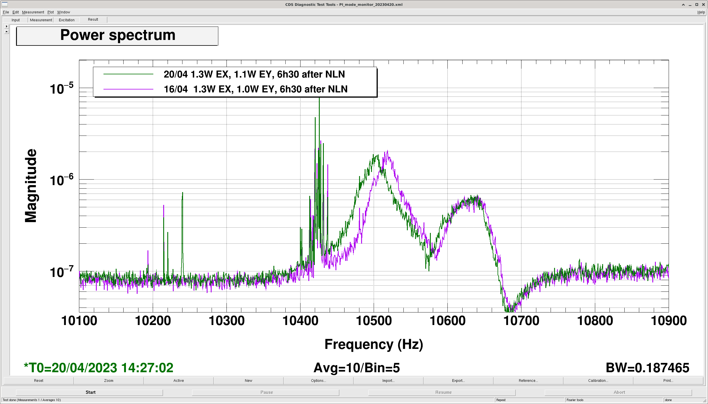
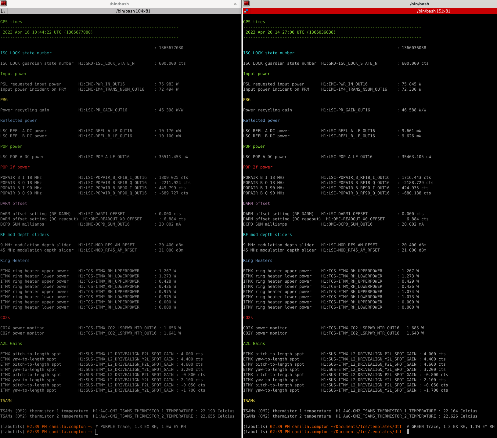
Using thermalized data (6hr30m after NLN), I compared the ETMY RH 1.0W to 1.1W settings. EX RH at 1.3W for both and CO2s both at 1.7W.

ETMY Ring Heater 1.0W 1.1W
Mode-seperation plot trace PURPLE GREEN
thermal_state_capture

2023 Apr 16 10:44:22 UTC

2023 Apr 20 14:27:00 UTC
DARM Contrast Defect No measurement 68715 1.7mW 68859
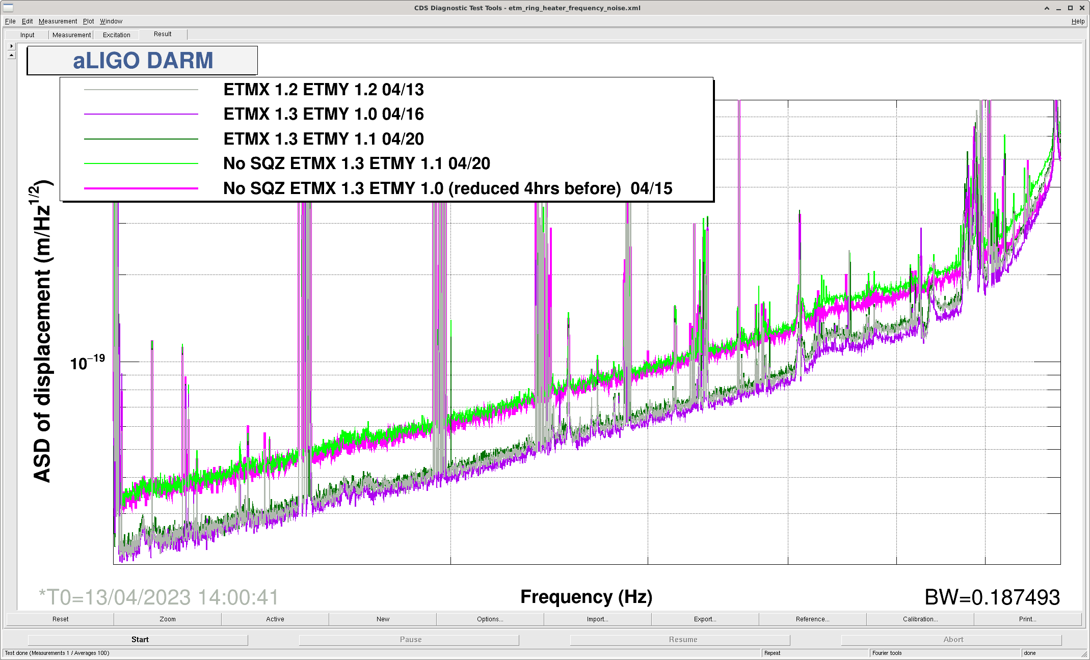
High frequency noise  PURPLE GREEN
Circulating Power X, Y 431, 433kW 431, 433kW

The high frequency noise plots traces with squeezing are the same times (PURPLE, GREEN), without squeezing are different times: for LIME GREEN 20/04, in the same lock just 3 hours before, for PINK 15/04 was 1day 9 hours before purple, with the same thermal settings but ETMY was reduced from 1.1W only 4 hours before.

These hint that the high frequency noise is getting worse but are less trustworthy than Elenna's frequency noise injection plots (alog 68860) as we don't know if the exact squeezing state and the DARM calibration changed between the two times. We didn't do a frequency noise injection plot with the 1.0W, 1.3W settings and 75W PSL input. We will wait for the IFO to thermalize with these 1.3, 1.2W RH settings are re-take the injections.

Images attached to this comment
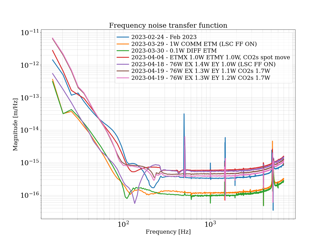
elenna.capote@LIGO.ORG - 09:08, Friday 21 April 2023 (68892)

This move improved our frequency noise further.

Images attached to this comment
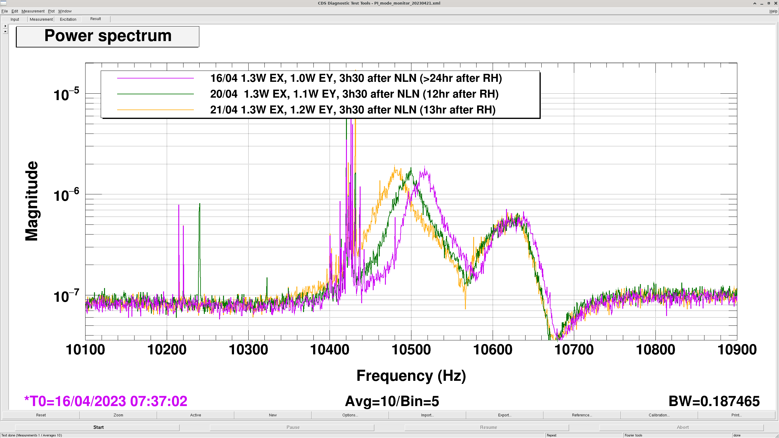
camilla.compton@LIGO.ORG - 09:49, Friday 21 April 2023 (68893)

And moved the lower mode-separation peak lower in frequency. See attached. Purple and green traces are the same locks as above plot but only 3h30 into the locks. Nothing else is changed, this was before the SR3 change.

Images attached to this comment
H1 CDS
david.barker@LIGO.ORG - posted 14:03, Thursday 20 April 2023 (68874)
Verified DAQ Frame Writer GPS time using h1calex IRIG-B signal

Similar to  Fuyao's timing investigation alog68801, I checked that the DAQ framewriter's GPS time is internally consistent between the frame file naming and the data timestamps within the frame.

Details are in this wiki

An overview of the process:

1. On NDS0 I took a full frame file at random, in this case H-H1_R-1365966080-64.gwf. I extracted the data for the H1:CAL-PCAL_IRIGB_DQ channel, which gave 16384*64 data points.

2. I took the first 16384 data points, which span the first second of the frame. I converted them into a CSV file and plotted them (see attachment)

3. By eye, I decoded the HH:MM:SS encoded in the IRIG-B signal (called Decode_UTC, leap seconds have not been applied)

4. I converted the frame filename's GPS time to True_UTC (leap seconds have been applied)

5. Verified Decode_UTC = True_UTC + 18

Result

In this case, Decode_UTC = 19:01:20, True_UTC = 19:01:02 which is correct.

Images attached to this report
H1 SUS (SUS)
rahul.kumar@LIGO.ORG - posted 13:46, Thursday 20 April 2023 (68832)
Undamped R0 Chain Transfer function measurement (0.01Hz bw) results for ITMX and ITMY

Jeff wanted me to re-take undamped high resolution (freq bw 0.01Hz) TF results for ITMX and ITMY R0 Reaction chain (previous results - damped & undamped TF discussed in LHO alog 68512).

The results for ITMX R0 chain is attached here, along with the individual osem performance if interested. Similarly, results for ITMY R0 chain and its osem perforamce is also attached below. I have compared the current results with the ones taken in the year 2021. The only thing I comment is that P dof magnitude is lower than the model (similar to the measurements taken 2 years ago). I couldn't see any big cross couplings between other dof.

The templates are stored at the following location,

/ligo/svncommon/SusSVN/sus/trunk/QUAD/H1/ITMX/SAGR0/Data

2023-04-18_1600_H1SUSITMX_R0_WhiteNoise_L_0p01to50Hz.xml
2023-04-18_1600_H1SUSITMX_R0_WhiteNoise_P_0p01to50Hz.xml
2023-04-18_1600_H1SUSITMX_R0_WhiteNoise_R_0p01to50Hz.xml
2023-04-18_1600_H1SUSITMX_R0_WhiteNoise_T_0p01to50Hz.xml
2023-04-18_1600_H1SUSITMX_R0_WhiteNoise_V_0p01to50Hz.xml
2023-04-18_1600_H1SUSITMX_R0_WhiteNoise_Y_0p01to50Hz.xml

/ligo/svncommon/SusSVN/sus/trunk/QUAD/H1/ITMY/SAGR0/Data

2023-04-18_1800_H1SUSITMY_R0_WhiteNoise_L_0p01to50Hz.xml
2023-04-18_1800_H1SUSITMY_R0_WhiteNoise_P_0p01to50Hz.xml
2023-04-18_1800_H1SUSITMY_R0_WhiteNoise_R_0p01to50Hz.xml
2023-04-18_1800_H1SUSITMY_R0_WhiteNoise_T_0p01to50Hz.xml
2023-04-18_1800_H1SUSITMY_R0_WhiteNoise_V_0p01to50Hz.xml
2023-04-18_1800_H1SUSITMY_R0_WhiteNoise_Y_0p01to50Hz.xml

Non-image files attached to this report
LHO VE
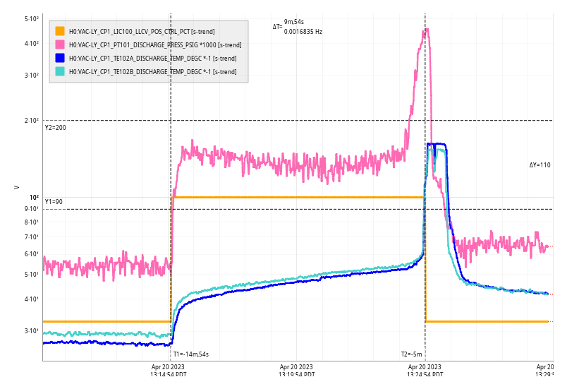
david.barker@LIGO.ORG - posted 13:43, Thursday 20 April 2023 (68871)
Thu CP1 Fill

Thu Apr 20 13:24:54 2023 INFO: Fill completed in 9min 53secs

Gerardo confirmed a good fill curbside

Images attached to this report
H1 ISC
elenna.capote@LIGO.ORG - posted 12:31, Thursday 20 April 2023 - last comment - 08:53, Friday 21 April 2023(68869)
Noise Budget of Cal Delta L at 76 W

I have made an updated noise budget using the Cal Delta L trace. Currently, there is no channel with online cleaning implemented, although that is a work in progress. We can use this noise budget and the traces to estimate how much more sensitivity we might gain when the cleaning is applied. Also, The current cal delta L trace is calibrated, so no calibration"fudge" was required to make this budget.

I reran all injections for the ASC, LSC, Laser and Input Jitter budget. Kevin and Vicky have been working on the proper calculation of the quantum vacuum trace, and the quantum subbudget. This budget uses the "semiclassical" estimation, which may not be fully accurate. However, for these purposes, I think it is sufficient.

I purposefully removed the PUM DAC noise from this budget, as I am worried that the calculation may be inaccurate. Craig recently switched coil driver states to get a projection of our current PUM DAC noise (alog 68489). Craig states that this projection is 20 times lower than what the noisemons are telling us. I think it is best to leave out the DAC noise until we can determine what is correct.

Subbudgets:

  • LSC: we are currently limited the most by MICH noise
  • ASC: we are currently limited the most by CHARD P
  • Laser noise: At low frequency, the jitter and frequency noise are comprable, at the mid range we are limited the most by jitter
  • Input Jitter: the largest contribution seems to be in yaw

Overall, compared to the 60W noise budget (alog 68382), the noise traces are about the same. That budget showed us limited by MICH (if you ignore PUM DAC), and limited by jitter. The high frequency laser noise has improved. The ASC budget has improved. We are still limited by unknown noise in the mid range.

I will follow up with a comparison of the NB traces at 60W and 76W. I think if we can subtract the jitter noise, especially in the bucket, the comparison will show us improved sensitivity in the region when operating at higher power.

Non-image files attached to this report
Comments related to this report
elenna.capote@LIGO.ORG - 22:37, Thursday 20 April 2023 (68882)

I ran a bruco on the quiet time used for the noise budget. https://ldas-jobs.ligo.caltech.edu/~elenna.capote/brucos/CAL_NB4_19/

I have not looked at all the results completely but I will point out the ones that I noticed:

  • SR2 coherence, such as M1_DAMP_P_IN1: https://ldas-jobs.ligo.caltech.edu/~elenna.capote/brucos/CAL_NB4_19/SUS-SR2_M1_DAMP_P_IN1_DQ.html
  • RM1 coherence: https://ldas-jobs.ligo.caltech.edu/~elenna.capote/brucos/CAL_NB4_19/SUS-RM1_M1_DAMP_L_IN1_DQ.html
  • This is already known, but MICH coherence: https://ldas-jobs.ligo.caltech.edu/~elenna.capote/brucos/CAL_NB4_19/LSC-MICH_IN1_DQ.html
  • Also known, but SRCL: https://ldas-jobs.ligo.caltech.edu/~elenna.capote/brucos/CAL_NB4_19/LSC-SRCL_IN1_DQ.html
evan.hall@LIGO.ORG - 08:53, Friday 21 April 2023 (68889)

The attachments compare the strain noise and comoving horizon volume for a time corresponding to this recent noise budget and for a time last month corresponding to an earlier noise budget. The sensitive volume is about the same for systems below 50 solar masses total — corresponding to something like a 70% increase compared to O3. But the IMBH sensitivity is vastly different, with the previous month's performance being much better than this month's.

Non-image files attached to this comment
H1 ISC (CAL, TCS)
jennifer.wright@LIGO.ORG - posted 19:48, Wednesday 19 April 2023 - last comment - 18:16, Monday 24 April 2023(68745)
Calibrated DARM during RH steps

Jennie, Elenna, Craig

For seven calibration meeasurements over the last two weeks I captured the thermal state of the interferometer, and used the broadband calibration injection taken at that time, and a 10 minute DARM measurement from a nearby quiet time, to get the calibration corrected DARM plots.

The thermal states were captured using thermal_state_capture.py in labutils.

The data was processed using Run_DARM_calib.ipynb in ligo/jennifer.wright/Documents/thermal_state

The BB injection measurements I used are in: /ligo/svncommon/CalSVN/aligocalibration/trunk/Runs/O3/H1/Measurements/FullIFOSensingTFs

The DARM spectra I used for quiet times are in /ligo/home/jennifer.wright/Documents/thermal_state
 

Calibrated DARM plots are saved in /ligo/gitcommon/labutils/pcal_bb_inj_quick_cal/plots and data is saved in /ligo/gitcommon/labutils/pcal_bb_inj_quick_cal/data 


BB Cal Injection Start DARM measurement start Input Power of IFO to nearest W Guardian State During Quiet time DARM measurement filename BB Cal Injection filename Thermal State Filename
1364697812 1364699612 60 600 2023-04-05_0313UTC_H1_DARMSPEC_0-1Hz.xml 2023-04-04_1945UTC_H1_PCALY2DARMTF_BB_3min.xml therm_state_1364697812.txt
1364775641 1364777441 60 700 2023-04-06_0050UTC_H1_DARMSPEC_0-1Hz.xml 2023-04-05_1727UTC_H1_PCALY2DARMTF_BB_3min.xml therm_state_1364775641.txt
 
1364872253 1364871648 60 700 2023-04-07_0300UTC_H1_DARMSPEC_0-1Hz.xml 2023-04-07_0316UTC_H1_PCALY2DARMTF_BB_3min.xml therm_state_1364872253.txt
 
1364882935 1364885358 70 700 2023-04-07_0649UTC_H1_DARMSPEC_0-1Hz.xml 2023-04-07_0612UTC_H1_PCALY2DARMTF_BB_3min.xml therm_state_1364882935.txt
 
1365031551 1365030706 70 700 2023-04-08_2311UTC_H1_DARMSPEC_0-1Hz.xml 2023-04-08_2327UTC_H1_PCALY2DARMTF_BB_3min.xml therm_state_1365031551.txt
 
1365040525 1365039740 70 600 2023-04-09_0142UTC_H1_DARMSPEC_0-1Hz.xml 2023-04-09_0412UTC_H1_PCALY2DARMTF_BB_3min.xml therm_state_1365040525.txt
 
1365385287 1365383774 78 700 2023-04-13_0115UTC_H1_DARMSPEC_0-1Hz.xml 2023-04-12_0145UTC_H1_PCALY2DARMTF_BB_3min.xml therm_state_1365385287.txt


I am going to add post some more DARM measurements from other days as I process them.

Non-image files attached to this report
Comments related to this report
jennifer.wright@LIGO.ORG - 18:44, Thursday 20 April 2023 (68857)

I plotted all the DARM spectra scaled by the PCAL BB measurement on the same graph, and corrected the parts where the coherence was low to match the unscaled DARM measurement.

Plot is in /ligo/home/jennifer.wright/Documents/thermal_state/pcal_corrected_darm_2023-04-05_0313UTC-to-2023-04-13_0115UTC.pdf

And code is in /ligo/home/jennifer.wright/Documents/thermal_state/Run_DARM_calib.ipynb.

Non-image files attached to this comment
jennifer.wright@LIGO.ORG - 18:16, Monday 24 April 2023 (68964)TCS

I updated the code to include GPS reference times for the DARM spectra and some additional measurements which were taken on the 10th, 14th and 20th of April. 

Code is in: /ligo/home/jennifer.wright/Documents/thermal_state/Run_DARM_calib_20230424.ipynb

Data for broadband calibration TFs to DARM is taken from:

/ligo/groups/cal/data/H1/measurements/PCALY2DARM_BB/

/ligo/svncommon/CalSVN/aligocalibration/trunk/Runs/O3/H1/Measurements/FullIFOSensingTFs/

Data for quiet times:

/ligo/home/jennifer.wright/Documents/thermal_state/*H1_DARMSPEC_0-1Hz.xml

Non-image files attached to this comment
H1 SQZ (SQZ)
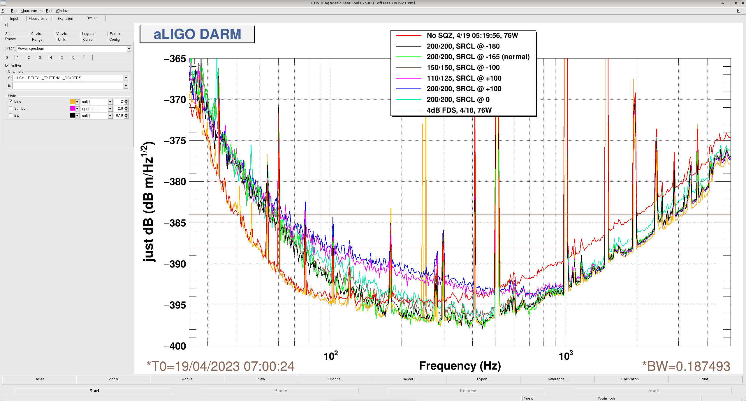
victoriaa.xu@LIGO.ORG - posted 11:24, Wednesday 19 April 2023 - last comment - 16:18, Thursday 20 April 2023(68814)
FIS with various SRCL offsets

Elenna, Vicky

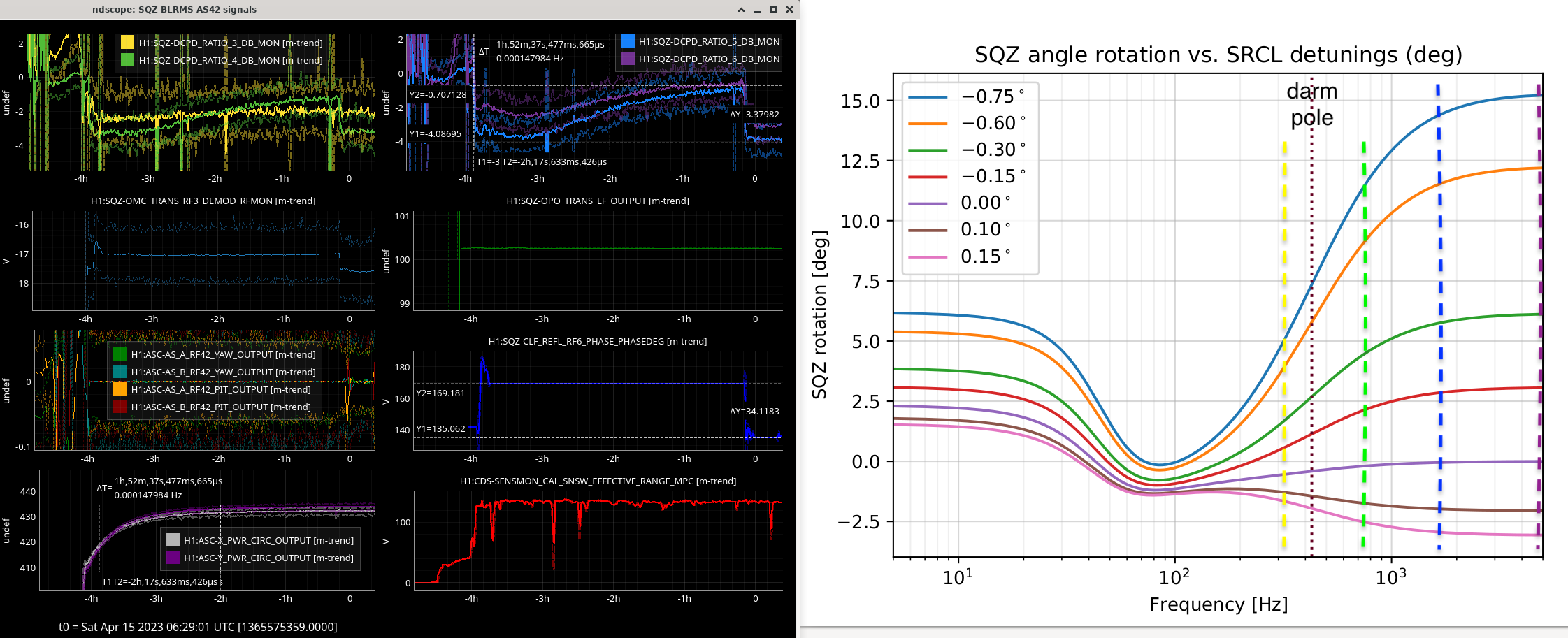
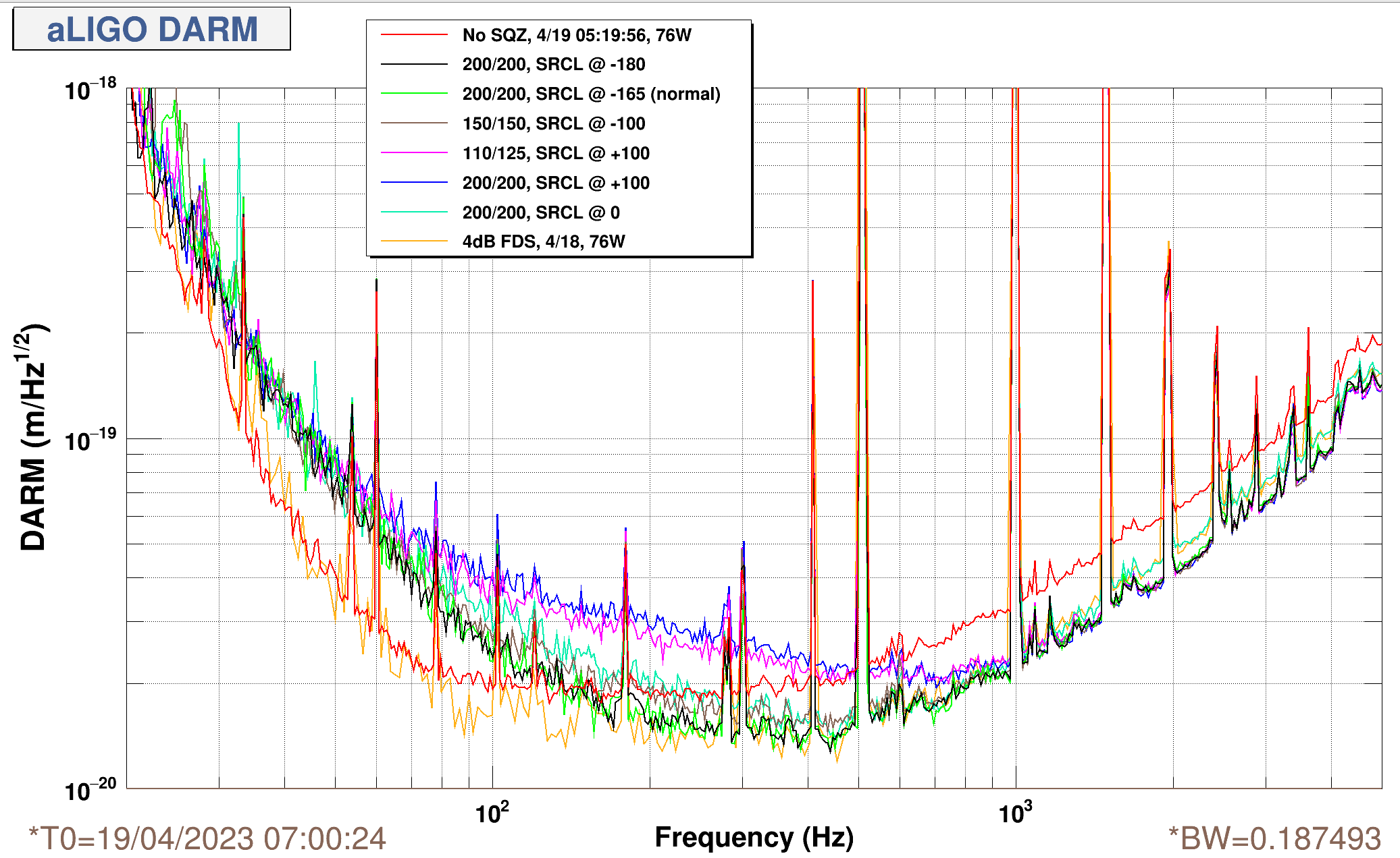
Operating with high generated sqz level ~ 16.5 dB, with IFO at 76W input, ~435 kW circulating, Elenna changed the SRCL offsets and we measured coherent SQZ rotations based on SRCL detuning.

Some takeaways:

  • SRCL detuning + filter cavity detuning compound as coherent sqz rotations. Mis-rotations between FC + SRCL hit hardest in the bucket. With high generated squeezing levels, this matters more, because the cavities rotate in the elevated anti-squeezing noise. We will need to pick a generated SQZ level for O4, which optimizes quantum noise in the bucket.
    • This is almost certaintly anti-squeezing getting rotated in, changing generated sqz levels changes this excess bucket sqz rotation from SRCL, see this plot from LHO:68251 where we varied gen. sqz levels.
  • FC is too narrow (~70 Hz FWHM) to un-rotate both the SRCL and RPN rotations of squeezing and anti-squeezing. FC is designed to un-rotate RPN (radiation pressure noise), largely below 100 Hz.
    • We have sometimes had to move the FC detuning to counter-act SRCL detuning, but this strategy has limited efficiency b/c FC is too narrow for SRCL, where the detuning is ~100-200 Hz around ~450 Hz.
  • Mode-mismatch possibly adds into this, but very different PSAMS configurations seem to produce only slightly different sqz phase rotations.
  • The DARM spring seems to evolve in the first 1-2 hours of IFO thermalization, we will try using the ADF to track this sqz angle rotation.
  • At present, more "negative" SRCL filter bank offsets are better for SQZ, in that they do not induce higher frequency early-onset of anti-squeezing.

Here, at each SRCL offset, we rotate the SQZ angle to be ~0 deg (aka phase sqz) at high frequencies > kHz. And so, we can see how SRCL acts as basically a broadband filter cavity to coherent rotate the sqz angle around the coupled cavity pole. The "SRCL offset" in the plot legend refers to the arbitrary filter bank offset counts, H1:LSC-SRCL1_OFFSET. We did not what physical SRCL detuning (in e.g. degrees) this corresponds to during this squeeze mearement, but this has been measured before at this circulating power. I also tried to explore whether we can see the compounded effects of coherent sqz angle rotations from both SRCL detuning + mode-mismatch together, but this mode-mismatch rotation seems much smaller an effect than SRCL detuning rotations.

Images attached to this report
Comments related to this report
victoriaa.xu@LIGO.ORG - 00:23, Thursday 20 April 2023 (68853)SQZ

Kevin Kuns, Vicky -- The way we see SRCL acting as a broadband filter cavity for squeezing is consistent w/calculations of how SRCL detuning changes sqz angle.

This is not necessarily a problem, as 0 detuning seems good for calibration and us, but it's kinda an interesting effect to see. The SRCL filter cavity action adds coherently with the FC detuning. I'd guess if we're in a bad spot with a big detuning, we could lose some range (guessest'd < 5 Mpc?) due to this misrotation of quantum noise in the bucket. Mostly, it does seem like a large SRCL detuning (like > 0.5 deg) might be non-ideal for squeezing, because FC is too narrowband to undo both significant SRCL detuning and RPN.

See here:  as IFO thermalizes for 2 hours to 430 kW, the amount of high-frequency squeeze angle change (~17 deg) during the first ~2 hours (left) is consistent with Kevin's calculations of sqz angle rotations at various SRCL detunings (right).

  • The observed range of squeeze angle rotation with thermalization is physically compatible with the range of SRCL detunings we've explored with the various H1:LSC-SRCL1_OFFSET filter bank offsets.
  • From our FIS measurements yesterday, we rotated the angle to set high-frequency FIS --> 0 at each SRCL offset. Compared to Kevin's plots on the right, this is equivalent to rotating the kHz squeezing back to "0", and observing how SRCL rotates low-frequency squeezing into anti-squeezing below the cc-pole ~450 Hz.
  • For sqz, a large SRCL detuning leads to the (non-ideal) blue trace in both kevin's calculations and the freq-indep sqz spectra from yesterday.

Over thermalization, our squeezer band-limited RMS monitors (SQZ BLRMS = H1:SQZ-DCPD_RATIO_*_DB_MON) monitors show drifts of:
 BLRMS_3 @ 325 Hz    (yellow, below darm pole) ~ 1dB
 BLRMS_4 @ 750 Hz    (green) ~ 2dB
 BLRMS_5 @ 1700 Hz   (blue)  ~ 3.2dB, ~34/2 = 17 degrees sqz rotation to recover high-frequency squeezing before/after thermalizing. SQZ rotation can be seen on ndscope, last column, 3rd from top (*_PHASEDEG ~ 2x sqz angle).
 BLRMS_6 @ 4700 Hz   (purple) ~ 2.8dB

High-freq sqz above the DARM pole (~450Hz) sees more rotation as expected, while sqz angle in the bucket is pretty stable w.r.t srcl detuning. We'll generally leave the squeeze angle optimized for the bucket, and let high-freq squeeze thermalize down. So, the sqz angle might look wrong at the start of locks (by ~15 deg, or ~30 deg on our slider).

Interesting alogs related to recent SRCL detunings:

  • late-Feb 2023. LHO:67613 has great plots at various SRCL offsets, with a very helpful table from Jeff comparing the "counts" of offset in H1:LSC-SRCL1_OFFSET to physical SRCL detunings in nm and degrees. His log 67613 describes fully, but some relevant points takeaways::
    • SRCL offset counts going from 50 --> -250 changed SRCL detuning by ~0.9 deg, from +0.15 --> -0.76 degrees. This range is calculated in Kevin's plots.
    • From Jeff's alog, quoting here: "calibration of the SRCL1_OFFSET as 3.04e-3 deg/ct or 9.00e-3 nm/ct."
    • From Kevin's calculations -- a SRCL detuning of about [-0.75, 0.15] degrees rotates the high-frequency SQZ angle from about [+15, -3] degrees.
      • Note: we have been setting the SQZ angle to optimize quantum noise reduction in the bucket ~100 Hz, which BNS range is most sensitive to. Conveniently, SQZ angle is pretty unaffected by SRCL detuning in the bucket, and only the high-freq (kHz+) squeezing angle is strongly swung around by the SRCL detuning (order ~10-20 deg rotation throughout thermalization), so this sqz thermalization shouldn't create too much range drift.
  • 68554 4/10, New SRCL offset at 78W, changed filter bank offset from -175 (set at 60 W) to -165. This is where we've been sitting now. Good list of other relevant alogs.
Images attached to this comment
victoriaa.xu@LIGO.ORG - 16:18, Thursday 20 April 2023 (68878)

Plot/file attached here in meters/rtHz, sligthly more intuitive to compare with calculations for radiation pressure noise.

Images attached to this comment
Non-image files attached to this comment
H1 SUS (ISC, OpsInfo)
elenna.capote@LIGO.ORG - posted 22:36, Tuesday 18 April 2023 - last comment - 13:55, Thursday 20 April 2023(68811)
ITMY modes 5/6 and 8 damping settings changed

It appears that again the best damping settings for ITMY violin mode 5/6 and 8 have changed again. I have not done any testing for what is best, but the current settings are ringing up the modes. I am setting the gains for these modes to zero in the guardian.

However, FM1, 6 and 10 with a gain of 0.1 is working again for ETMY mode 1, so I have updated the guardian accordingly.

Comments related to this report
austin.jennings@LIGO.ORG - 11:25, Wednesday 19 April 2023 (68826)

I found that FM1, FM2, and FM10 with a Gain of -0.4 works well for ITMY 8 (tested across two locks @ 76 W). Loaded setting into lscparams.

elenna.capote@LIGO.ORG - 19:23, Wednesday 19 April 2023 (68854)

This evening I have been damping ITMY 5/6 using a reduced gain but the same filter settings, FM6 and FM10. Currently both modes are decreasing, according to the narrow band monitors, using a gain of -0.025. I started with -0.01 and ramped the gain up slowly. The broader monitors show mode 6 decreasing and mode 5 staying constant.

rahul.kumar@LIGO.ORG - 13:55, Thursday 20 April 2023 (68873)

Yesterday afternoon I was able to damp IY05/06 using a lower gain (-0.025), even though the lock was not long but still the drive was coming down - see ndscope.

Images attached to this comment
Displaying reports 20901-20920 of 87770.Go to page Start 1042 1043 1044 1045 1046 1047 1048 1049 1050 End