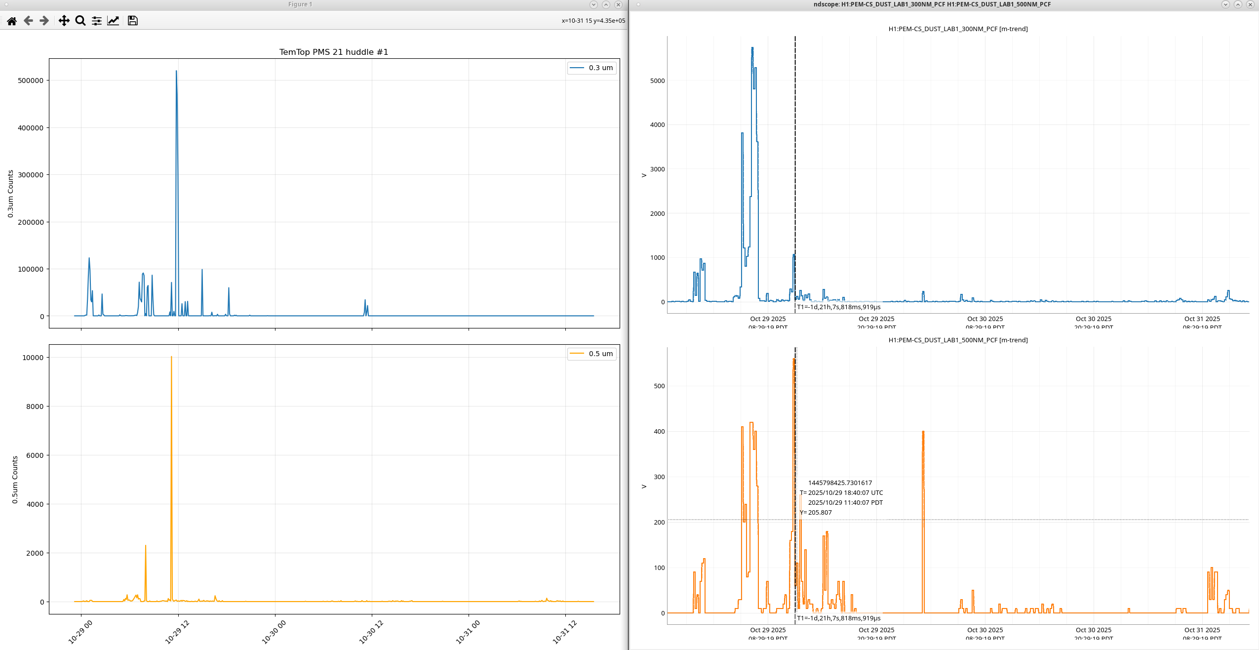
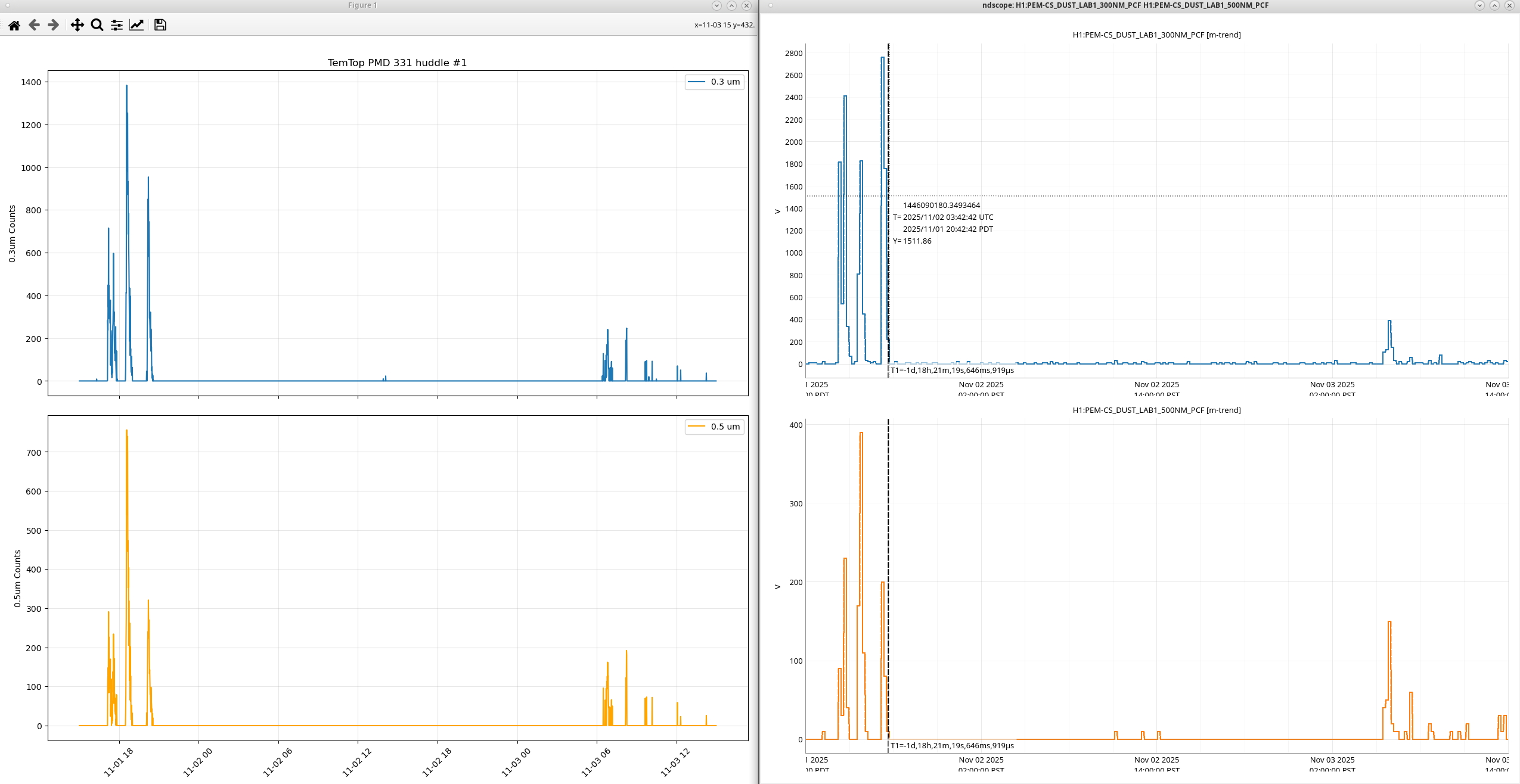
I've ran a few different huddle test with the new TemTop dust monitors against 3 different MetOne GT521s. The first tests I ran in the Optics lab and Diode room showed some discrepancies between the spike times but that could be due to a difference in sample times vs the two dust monitors. The PMS21 and GT521s both sample for 60 seconds then hold for 300s, but the PMD331 does not have a built in hold time so it samples continuously or manually. The PMS21 usually reads an order of magnitude or two lower than the other two which makes me wonder if it needs a scale factor, but it also sees these big spikes occasionally that the others don't see which is confusing. The flow rate is listed as being 0.1 CFM on the PMS21, but the GT521s and the PMD331 are also listed as having flow rates of 0.1 CFM. CFM = Cubic feet / minute, its also = 2.83 L/min which is what I read when running the flow test on all of the DMs. *Also the times do not account for daylight savings, so each y-axis timestamp is actually an hour behind the actual PST*.
Test 1 - Optics Lab:
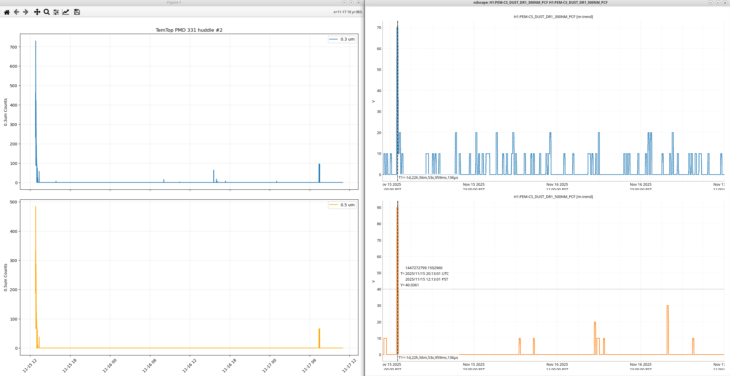
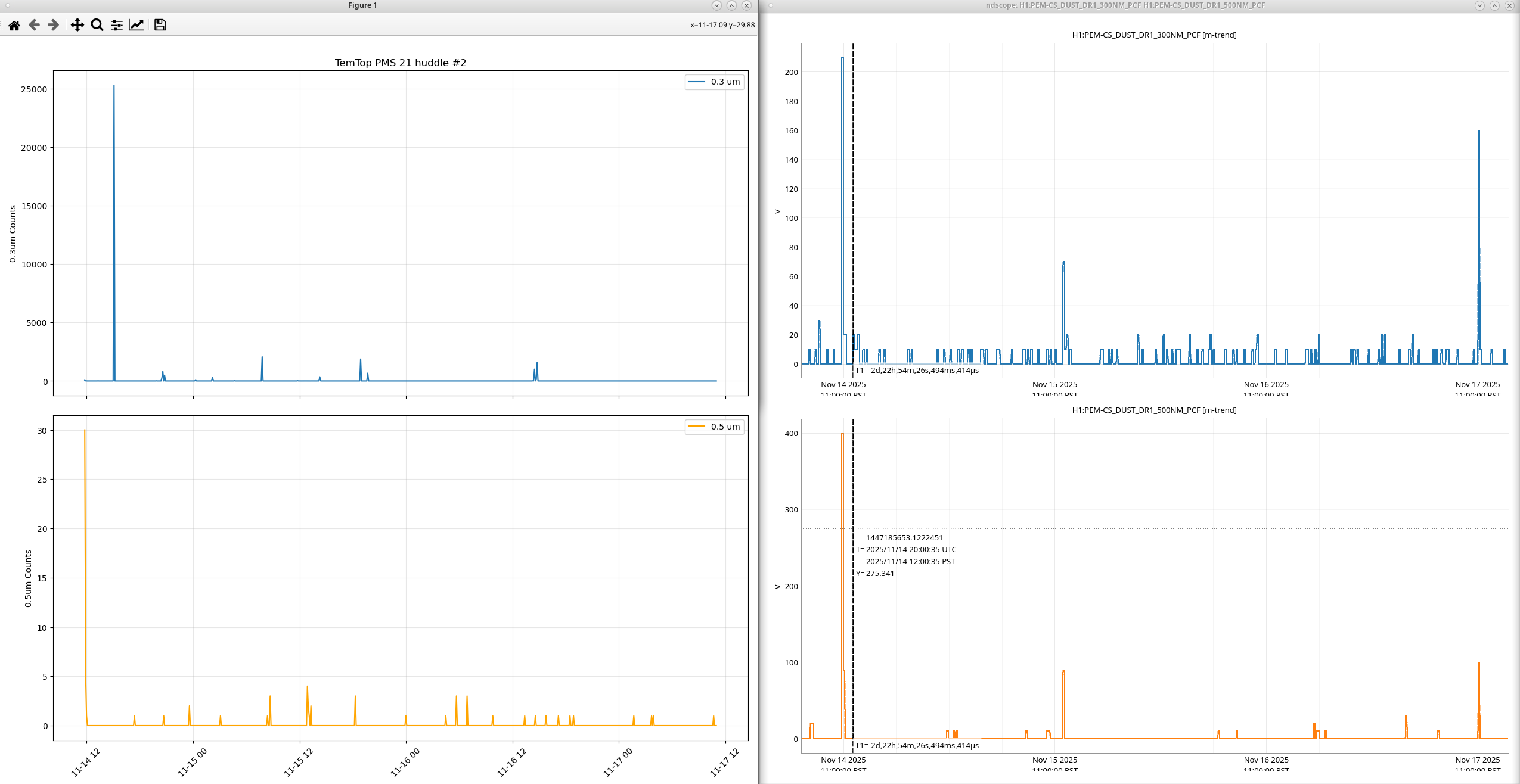
I tested the TemTops one at a time in the Optics lab, the results of the PMD331 and the results of the PMS21.
Test 2 - Diode Room:
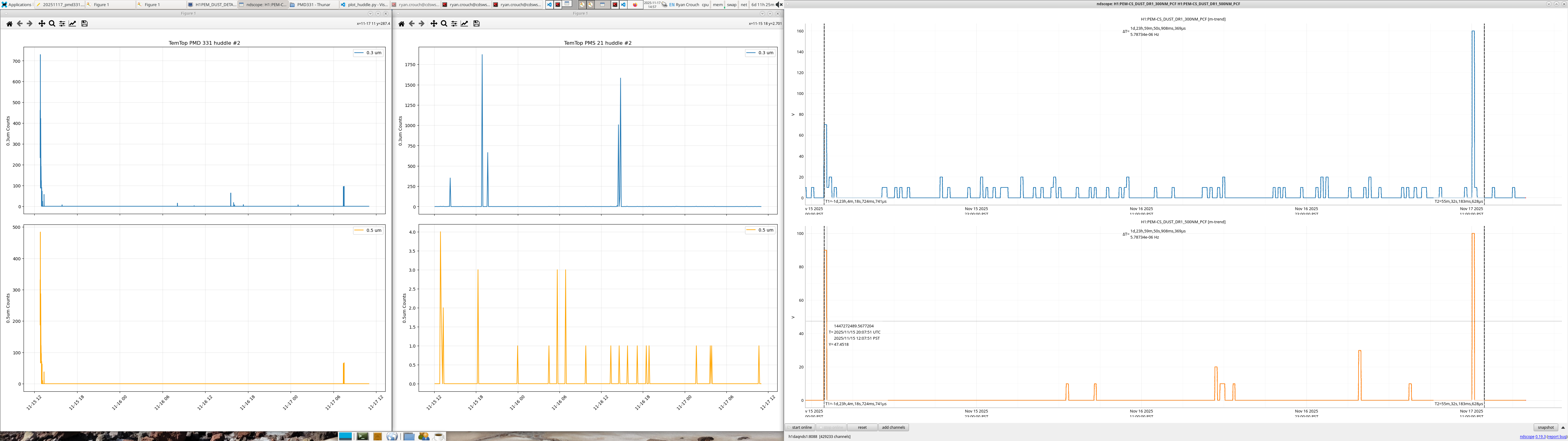
I tested the TemTops at the same time in the Diode room, I started off with only the PMS21 then I added the PMD331. For only the PMS21 we saw the these counts, for only the PMD331 we saw these counts, and for both of them we saw these counts,all against a MetOne GT521s.
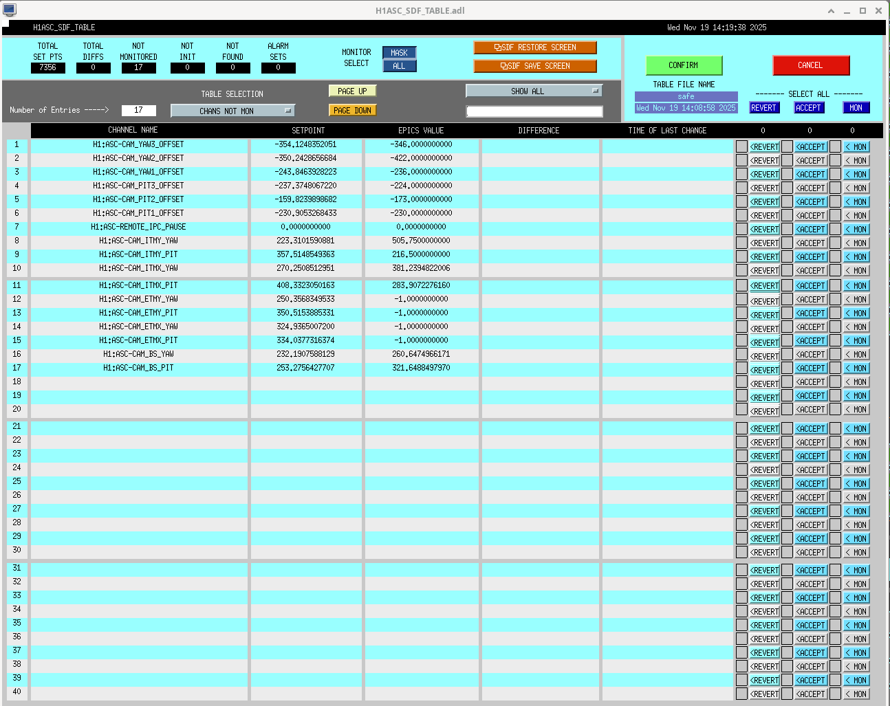
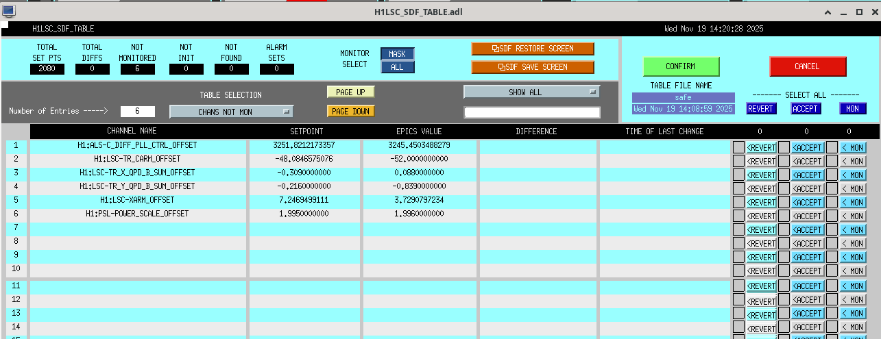
Test 3 - Control Room:
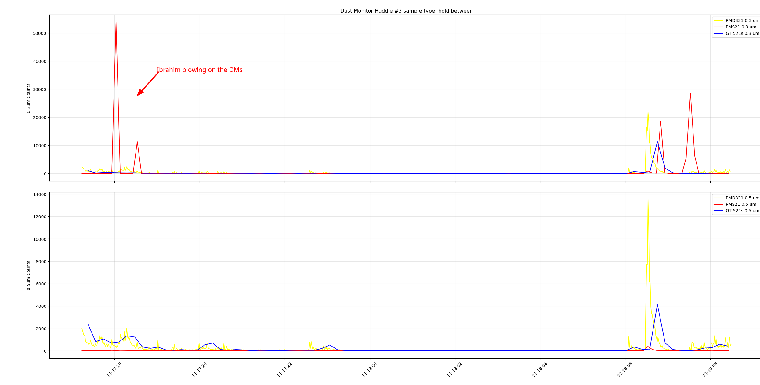
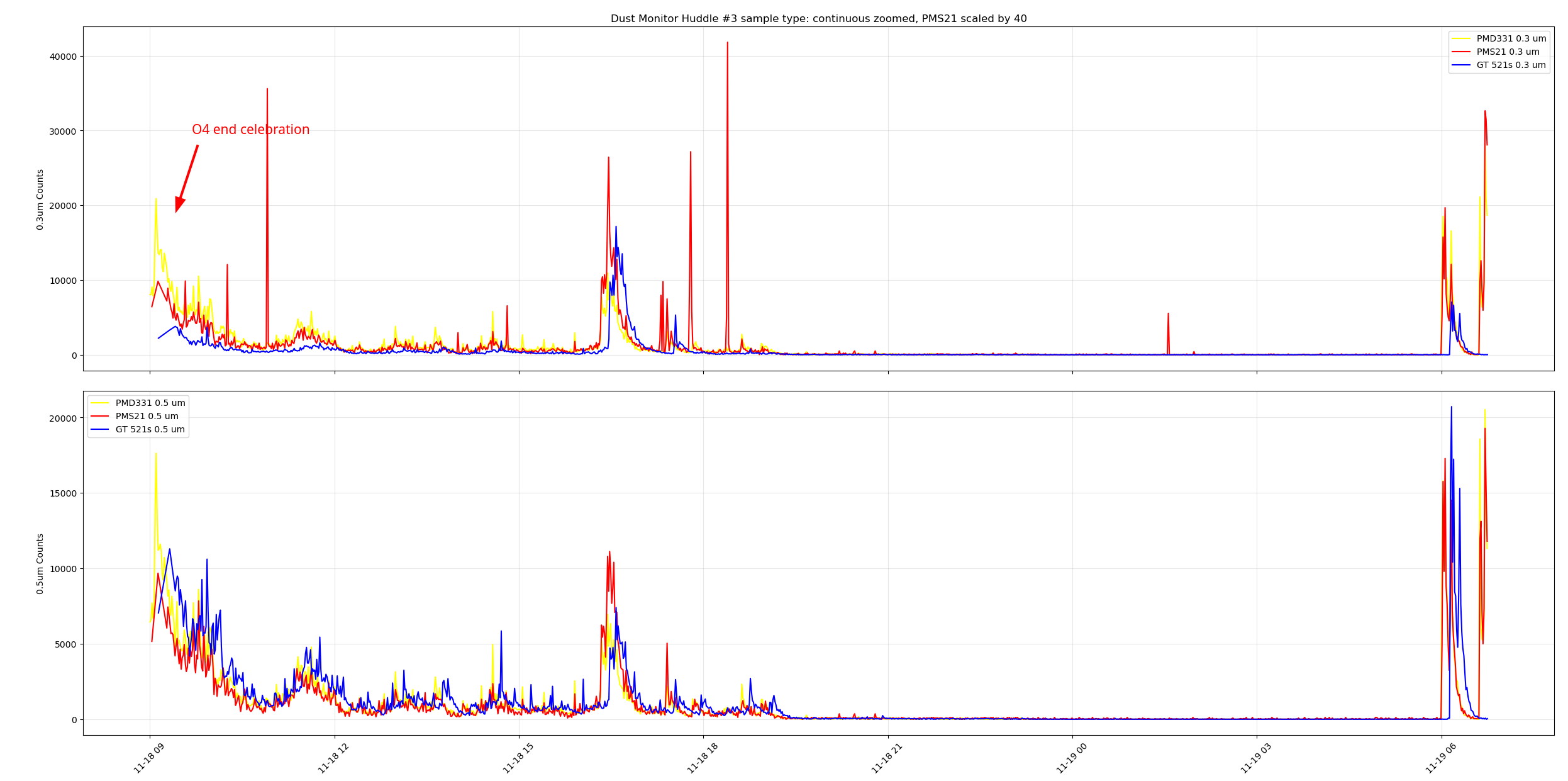
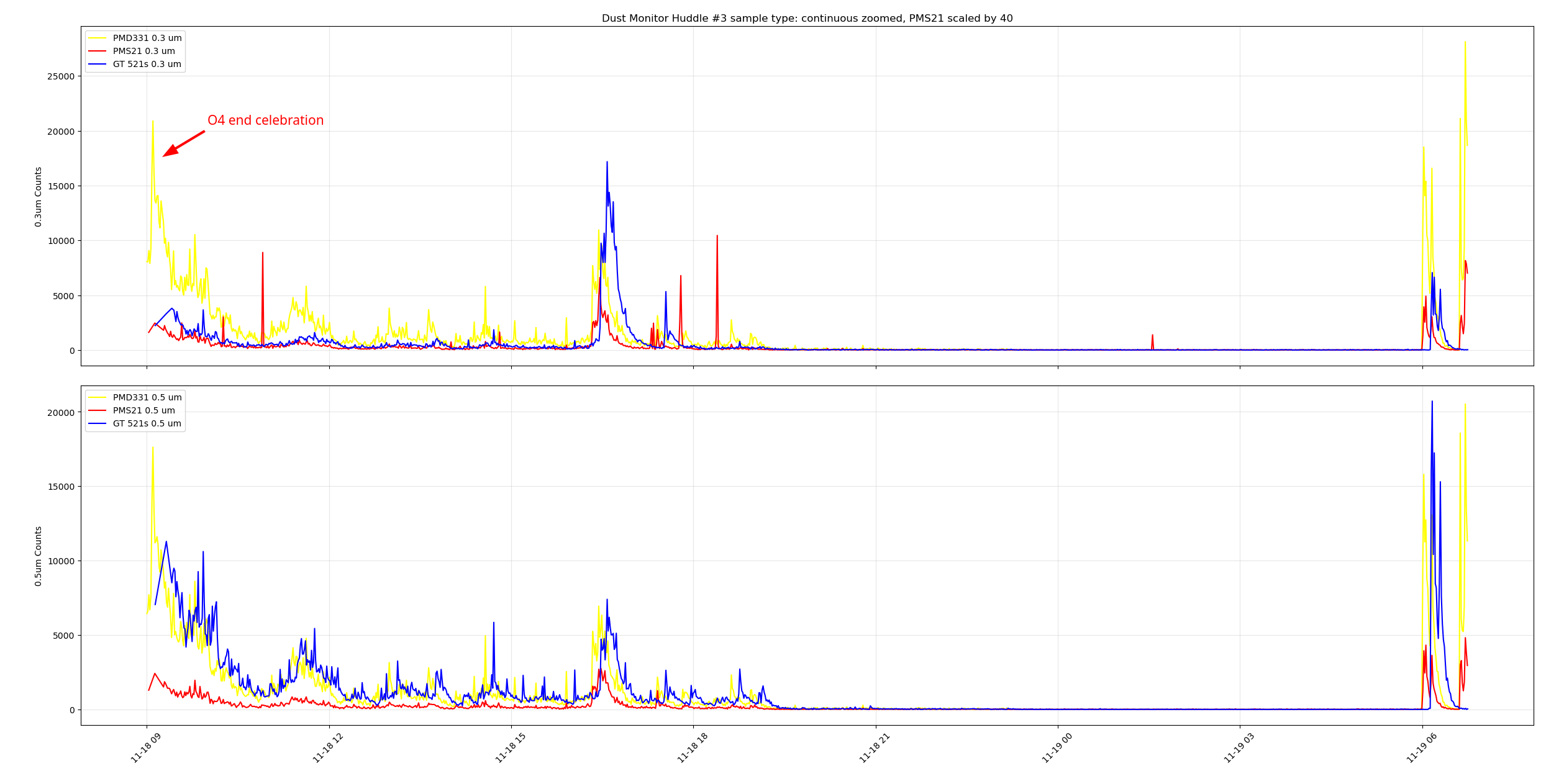
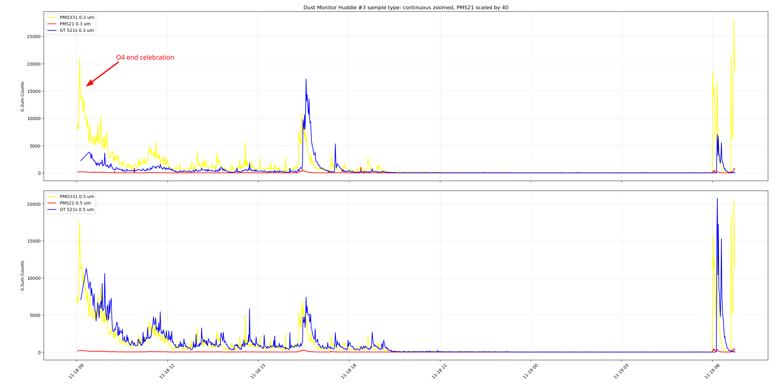
I tested three dust monitors at the same time in the control room ( I grabbed a spare pumped GT521s from the storage racks by the OSB receiving, it's our last properly working spare). I did a day of samples with holds enabled and a day of continuous sampling. When the dust monitors were sampling at slightly different intervals we saw the peaks offset from each other such as at 11-18 ~07:00 PST at the right of the plot. During the continuous testing we can see the peaks from everyone coming into the control room for the end of O4 celebration, I'm not sure why there's some time between the peaks, zooming in on this plot to cut out the large peaks from said celebration we can see the PMD331 and the MetOne GT521s following each other pretty closely, but the PMS21 wasn't really reading much, there are small bumps around where the peaks from the other DMs are. Adding a scale factor of 10 to the PMS21 counts yield a better looking plot, playing with the scale factor till the PMS21 counts looked more in-line with the other DMs I got to a scale factor of 40 to get this plot.


Last night we were stuck at 10W with the IMC unlocked because H1_MANAGER requested ISC_LOCK run an initial alignment while ISC_LOCK was already powering up to 10W to run check MICH. In the DOWN state of ISC_LOCK, it requests LASER_PWR to 2W, BUT ALIGN_IFO repeatedly requests LASER_PWR to 10W while the power is still adjusting. I have no idea why this would be necessary, and Sheila and I agreed that we should take it out. I've removed that portion of code and reloaded that node. If we run into whatever issue someone was trying to fix again, we will come up with a different solution.