Follow up to Oli's measurements on [LHO: 87362].
We fit the eight (yes, eight!) transfer functions needed for a full L-P M1 OSEM estimator for PR3. The measurements for PR3 were remarkably clean, so it was pretty close to just automated. I spent a lot of time cleaning up Ivey's code so it hopefully can be scaled up to other suspensions more easily.
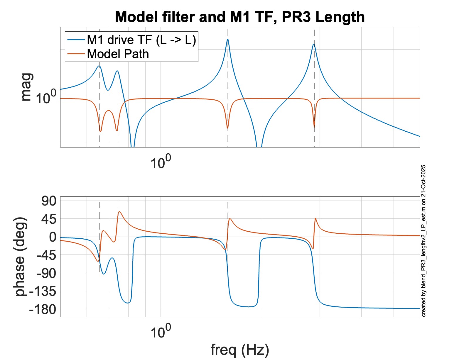
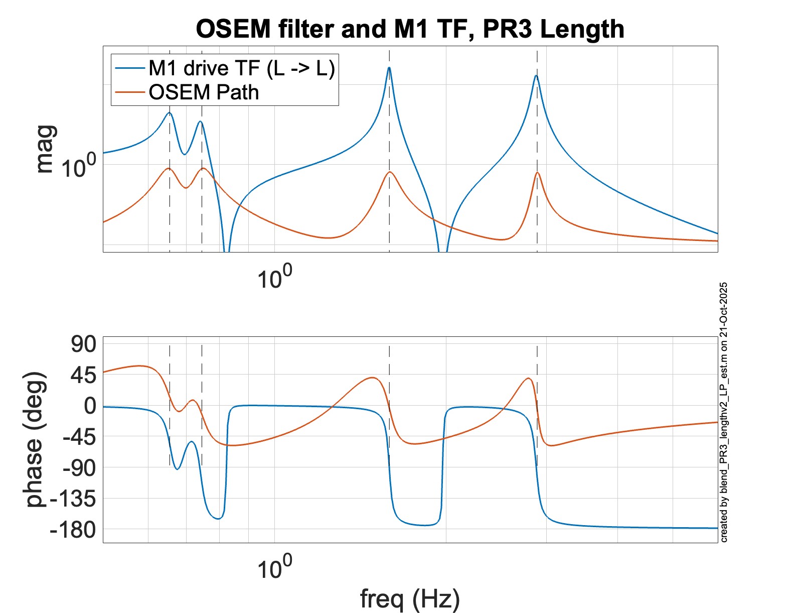
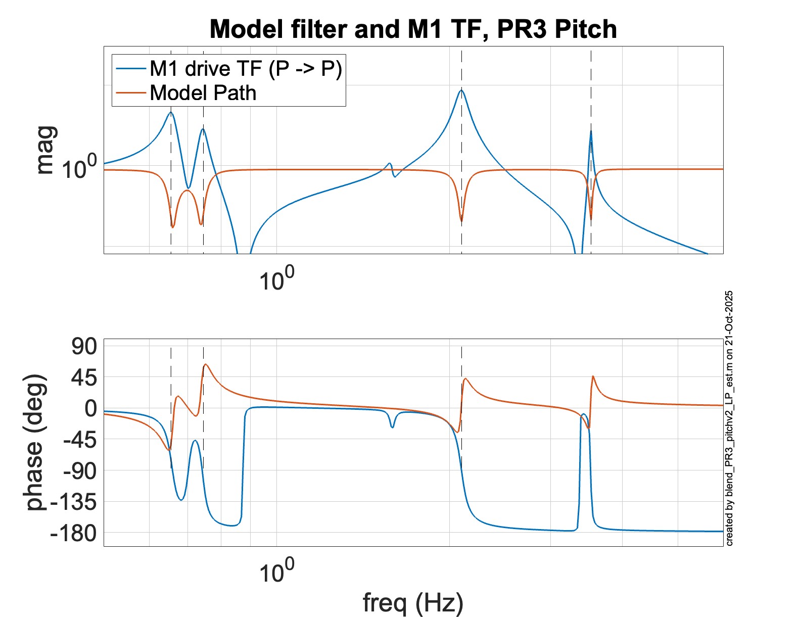
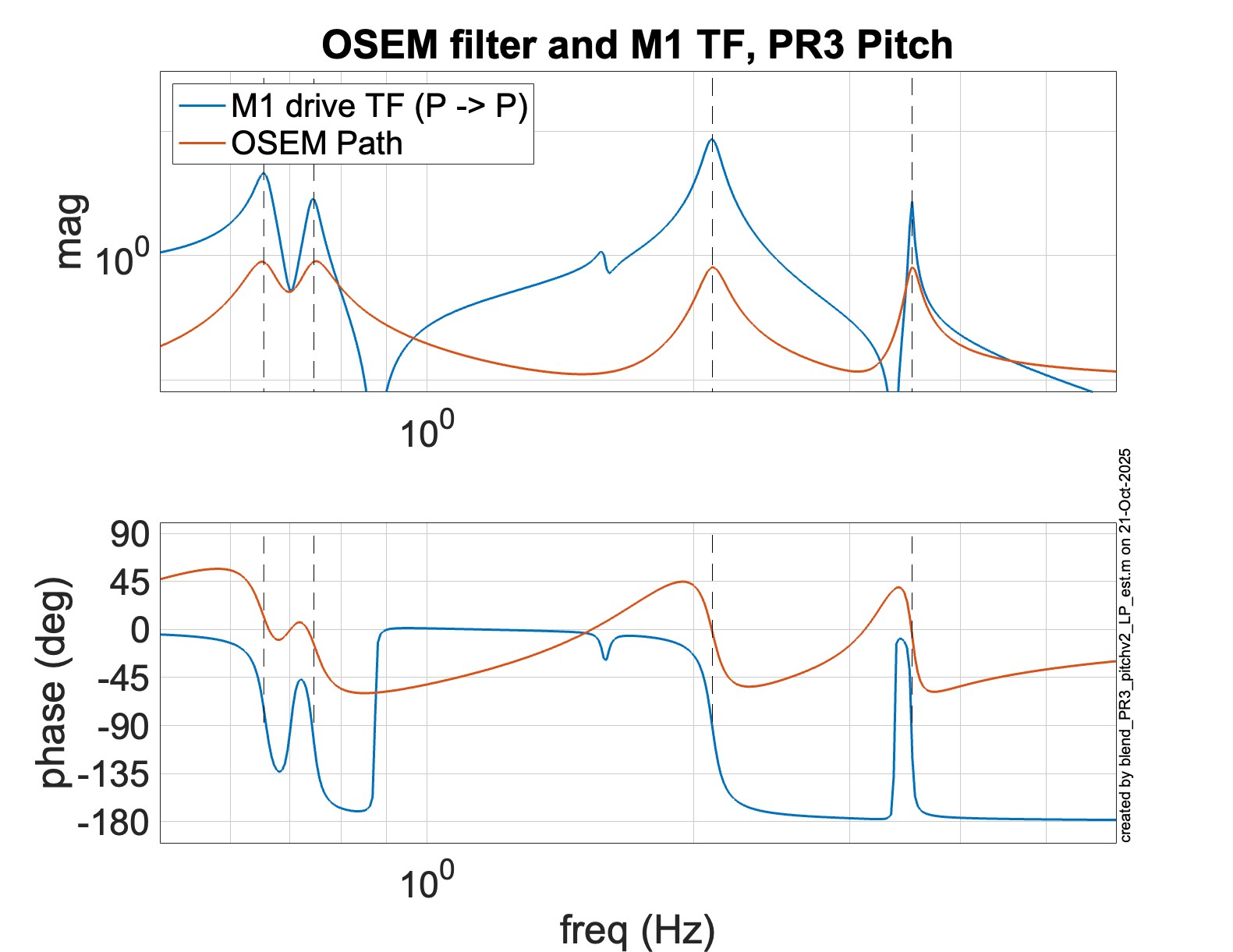
The relevant fits are shown in the attached .pdf They are suspoint {L,P} to M1 {L,P} (4 fits), and M1 drive {L,P} to M1 {L,P} (4 fits). The estimator's control stability only depends on the M1 drive models, which are fit surprisingly well.
I will note that the L-P plant for PR3 is remarkably reciprocal, and I actually expect to see good performance of the estimators when we try them.
The fits were committed to the sus svn together with a script to install them under revision 12734.
The files live in (svnRoot)/sus/trunk/HLTS/Common/FilterDesign/Estimator/ and are named:
make_PR3_estimator_LP.m
fits_H1PR3_LP-2025-10-07.mat
_______________
These are the .zpk for the fits:
SUSPOINT TO M1
Suspoint L to M1 L fit
zpk([0,0,-0.223-4.338i,-0.223+4.338i,-0.04-7.231i,-0.04+7.231i,-0.122-15.233i,-0.122+15.233i],[-0.07-4.099i,-0.07+4.099i,-0.111-4.714i,-0.111+4.714i,-0.11-9.997i,-0.11+9.997i,-0.234-18.094i,-0.234+18.094i],-0.001)
Suspoint L to M1 P fit
zpk([0,0,0.954-6.919i,0.954+6.919i,-0.925-7.247i,-0.925+7.247i,-0.03-17.396i,-0.03+17.396i,-0.026-20.357i,-0.026+20.357i],[-0.083-4.115i,-0.083+4.115i,-0.09-4.669i,-0.09+4.669i,-0.107-9.984i,-0.107+9.984i,-0.288-13.181i,-0.288+13.181i,-0.275-18.054i,-0.275+18.054i,-0.084-22.109i,-0.084+22.109i],0.373)
Suspoint P to M1 L fit
zpk([0,0,-0.204-4.277i,-0.204+4.277i,-0.081-9.662i,-0.081+9.662i,0.016-17.983i,0.016+17.983i],[-0.044-4.018i,-0.044+4.018i,-0.102-4.661i,-0.102+4.661i,-0.028-9.938i,-0.028+9.938i,-0.018-18.044i,-0.018+18.044i],0)
Suspoint P to M1 P fit
zpk([0,0,-0.02-4.046i,-0.02+4.046i,-0.005-4.779i,-0.005+4.779i,0.017-5.716i,0.017+5.716i,0.003-9.719i,0.003+9.719i,-0.175-9.79i,-0.175+9.79i,0.075-13.176i,0.075+13.176i,0.001-22.098i,0.001+22.098i],[-0.01-4.018i,-0.01+4.018i,-0.06-4.157i,-0.06+4.157i,-0.06-4.653i,-0.06+4.653i,-0.007-4.797i,-0.007+4.797i,0-9.765i,0+9.765i,-0.017-9.957i,-0.017+9.957i,-0.036-13.12i,-0.036+13.12i,-0.019-22.115i,-0.019+22.115i],-0.001)
M1 DRIVE TO M1
M1 drive L to M1 L fit
zpk([-0.137-4.329i,-0.137+4.329i,-0.017-5.169i,-0.017+5.169i,-0.037-12.394i,-0.037+12.394i],[-0.098-4.128i,-0.098+4.128i,-0.09-4.66i,-0.09+4.66i,-0.103-9.985i,-0.103+9.985i,-0.245-18.089i,-0.245+18.089i],0.142)
M1 drive L to M1 P fit
zpk([1.391-5.654i,1.391+5.654i,-1.723-6.019i,-1.723+6.019i,-9,12.605,0.233-16.247i,0.233+16.247i,-0.042-19.777i,-0.042+19.777i],[-0.093-4.125i,-0.093+4.125i,-0.088-4.646i,-0.088+4.646i,-0.102-9.984i,-0.102+9.984i,-0.292-13.17i,-0.292+13.17i,-0.264-18.072i,-0.264+18.072i,-0.085-22.117i,-0.085+22.117i],0.119)
M1 drive P to M1 L fit
zpk([1.425-5.579i,1.425+5.579i,-1.619-6.117i,-1.619+6.117i,-9.724,13.511,0.26-16.388i,0.26+16.388i,-0.122-19.664i,-0.122+19.664i],[-0.092-4.129i,-0.092+4.129i,-0.097-4.664i,-0.097+4.664i,-0.081-9.967i,-0.081+9.967i,-0.298-13.165i,-0.298+13.165i,-0.27-18.058i,-0.27+18.058i,-0.08-22.14i,-0.08+22.14i],0.115)
M1 drive P to M1 P fit
zpk([-0.068-4.408i,-0.068+4.408i,-0.012-5.489i,-0.012+5.489i,-0.108-10.011i,-0.108+10.011i,-0.023-21.169i,-0.023+21.169i],[-0.089-4.125i,-0.089+4.125i,-0.079-4.666i,-0.079+4.666i,-0.104-9.96i,-0.104+9.96i,-0.29-13.181i,-0.29+13.181i,-0.084-22.141i,-0.084+22.141i],82.922)


Several Guardian nodes reloaded at 07:45 this morning, modifed sqzparams.py
sqzparams.py was modifed yesterday evening at 19:40 and SQZ_ANG_ADJUST was reloaded at that time to apply the code change. Five other Guardian nodes import sqzparams.py and were in CFC state this morning.
I took the opportunity to test the automatic loading of these nodes after verifying none use the modified lines in sqzparams.py. The command is
guardian_modified_not_loaded --load-nodesa confirmation is required before proceeding with the load. The nodes loaded were (pre-load params shown):
======================================================================================
Node Status File Source Date Running Date
======================================================================================
SQZ_CLF_LR NOT LOADED sqzparams.py 19:40 Mon 20oct2025 08:49 Tue 14oct2025
SQZ_FC NOT LOADED sqzparams.py 19:40 Mon 20oct2025 10:19 Mon 20oct2025
SQZ_MANAGER NOT LOADED sqzparams.py 19:40 Mon 20oct2025 10:19 Mon 20oct2025
SQZ_OPO_LR NOT LOADED sqzparams.py 19:40 Mon 20oct2025 19:29 Mon 20oct2025
THERMALIZATION NOT LOADED sqzparams.py 19:40 Mon 20oct2025 10:18 Mon 20oct2025
======================================================================================
GRD CFC is now green.