Drove to X-End to troubleshoot GV20 AIP, the controller for the pump was ON, but it had the high overload light ON, a.k.a. red light. After tapping on the pump body twiece with a short success, the decision is to swap the pump on Tuesday. This AIP appears to be very old, probably one of the original ones.
Filed a FRS ticket 14012
Summary: After a DOWN TIME OF 3hrs 6min, H1 is back to Observing from a High Voltage Vacuum pressure trip at HAM6. Made it back to NLN on 1st attempt.
Locking Notes:
J. Kissel, G. Merano, C. Vorvick, R. McCarthy, K. Kawabe, C. Compton, K. Ryan
The most recent lock loss (from Nominal Low Noise at 22:59 UTC) is very likely due to a failure in the RGA (or its controller) on HAM6, which had "temporarily" been used as the vacuum interlock signal for the high voltage ("temporarily" -- a month or more now...). Unfortunately, due to the "temporary" nature of the set up, we don't have a read-back on that RGA, so we can't confirm, but all indirect evidence during the aftermath points to it.
Richard, Kyle, and Gerardo have now switched the HAM6 HV interlock signal back to the "nominal" configuration, i.e. using the HAM6 PT110 ion gauge (H0:VAC-LX_Y0_PT110_MOD1_PRESS_TORR), which is also measuring the HAM6 pressure. We can confirm that there was no significant pressure increase in the vacuum system, i.e. it has remained around ~2e-7 Torr during this entire event (though we did see a small, ~0.05 Torr, sharp increase at the time of lock loss.)
This brought the HAM6 HV back, and we're now re-acquiring.
Details will be in the comments by me and others mentioned above.
Here's the breadcrumb trail we followed in order to figure out this problem:
(1) Upon attempting to re-acquire, the ISC_LOCK guardian got stuck on PRMI ASC, throwing a notification that that the ISC_DRMI guardian was throwing a notification.
(2) The ISC_DRMI notification was "WFS DC centering railed." So, Cheryl and I went in to the DC centering screen and tried to clear the OMs, which were indeed receiving very huge numbers. The reset buttons on that DC centering screen didn't work, and -- Jenne says later when she joins the diagnosis party -- it's "because the integrators have been moved to the suspensions, the DC centering screen won't look like it's sending out garbage signals any more."
(3) After reseting, Cheryl noticed that the AS_A and AS_B signals were quite zero.
(4) Simultaneously, we say the DIAG_MAIN was throwing a notification that the high voltage for the Fast Shutter was off.
At this point, I "remembered" (i.e. searched "HAM6 high voltage" in the aLOG) the problem we'd back in October 26 (see LHO aLOG 52786):
""(3) Our next stumping point after initial alignment of the green ams was done, was the failure to repair the HAM6 PT110 pressure sensor today (LHO aLOG 52775). This sensor was serving as our high voltage interlock sensor, so since it didn't work suddenly near the end of maintenance, it tripped the high voltage off. Since the high voltage was off, the fast shutter was closed, which meant that the QPDs at the AS port (AS_A, AS_B, AS_C) were blocked, and the input alignment wouldn't work -- with the symptom being that the ASC DC centering loops were railing. It took Jenne putting two-and-two together to understand this connection path as to why the automated ALIGNING_INPUT step wasn't progressing.
TJ has now added a check for the fast shutter being open during this step to the automated initial alignment guardian so that we don't get bit by this again.""
Confident that "the" HAM6 vacuum pressure gauge (not yet knowing/remembering about the temporary setup situation) had tripped the high voltage in HAM6, which popped up the FAST SHUTTER, which blocked the light to the AS_A and AS_B QPDs, i.e. the WFS DC centering error signals, like had happened during initial alignment back in October,
(5) Camilla and I went out the CER mezzanine to look at the high voltage power supply. They were indeed off. We tried the "level one" fix of just turning the supplies, which didn't do anything.
(6) Keita then joined us, remembering more about the interlock, and used a nearby ladder to look *on top of the rack* and found the HV interlock system.
(7) We took a few pictures, and then hit the red reset button which did nothing (i.e. did not change the lights on the beckhoff module that serves as the interlock, nor did it allow the power supplies to come back on)
(8) We power cycled the interlock chassis, and hit the reset button again, and while it changed the status lights on the beckhoff module, it still didn't allow the power supplies to be turned on. (We found out later, that nominally, *all* the lights on the interlock module will be on if things are functioning correctly.)
Time to call in the cavalry: Richard, Gerardo, and Kyle.
Before Richard arrived, he had me
(9) check the power supply to the RGA's ion pump controller to confirm all was well. Not knowing anything about this, I brought Gerardo with me -- but he didn't hear the conversation -- so he took me out to look at the PT110 ion pump controller, and we confirmed all was happy with *that* controller.
Richard went out to the mezzanine and
(10) Tested the interlock module functionality by removing the real pressure signal and replacing it with a consistently jumpered mimicked high pressure gauge input, and the interlock became functional, thus he concluded that something was wrong with the pressure signal coming from HAM6.
At this point, Gerardo and Kyle had in parallel gone out to the HAM6 area to check on things, and Richard met them out there, concluding that
(11) Indeed, the RGA's ion pump and/or its controller was indeed quite dead.
Thus -- they took action as described in the main aLOG and reverted the pressure signal to the PT110, instead of the RGA's ion pump.
In order to hopefully shorten the wild goose chase next time, I've added 4 more words to the ISC_DRMI warning about "WFS DC centering railed" -- it now says "WFS DC centering railed, consider checking HAM6 HV."
Attached figures:
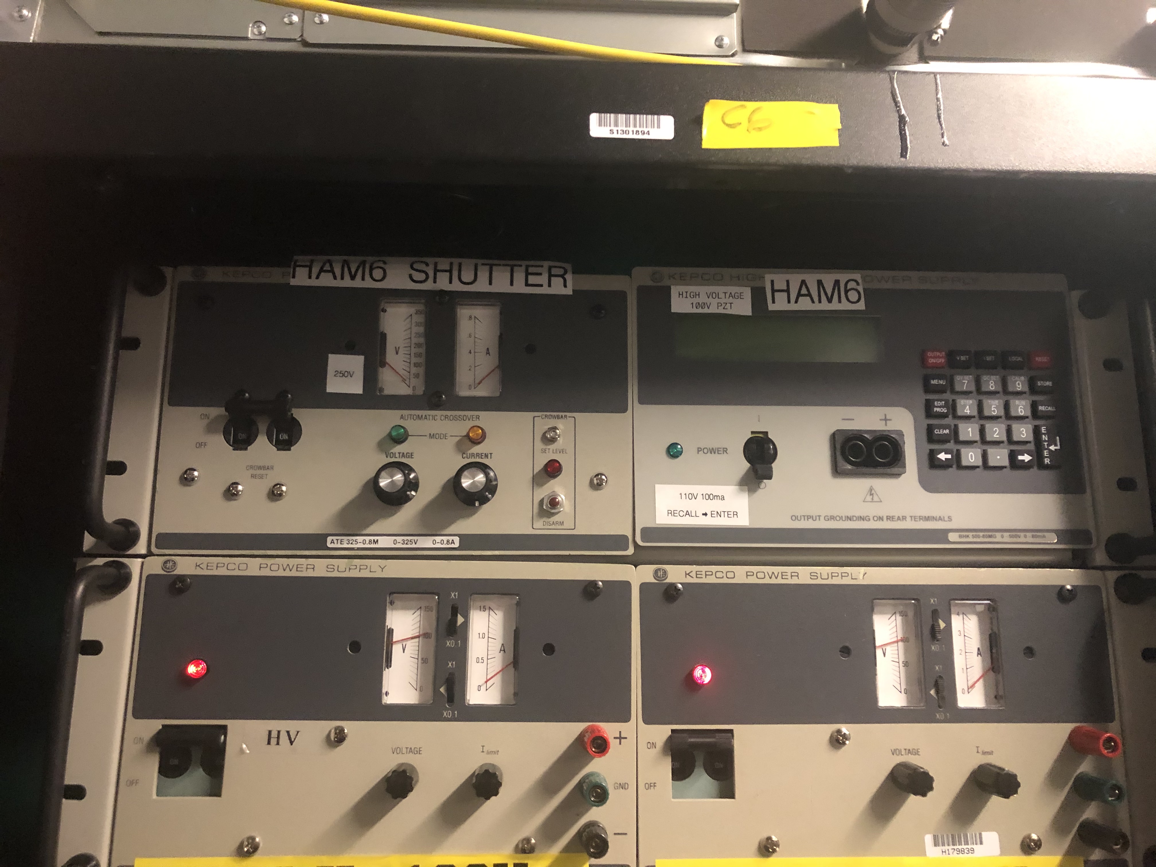
(A) IMG_2295.jpg -- the Fast Shutter and HAM6 high voltage power supplies in the Mezzanine above the CER, shown as they were found by Camilla and I in step (5): The HAM6 SHUTTER power supply power switch was in the ON position, but no other lights were on, and the analog dials were reading zero. The digital HAM6 High Voltage power supply's power switch was in the OFF position, and nothing appeared alive.
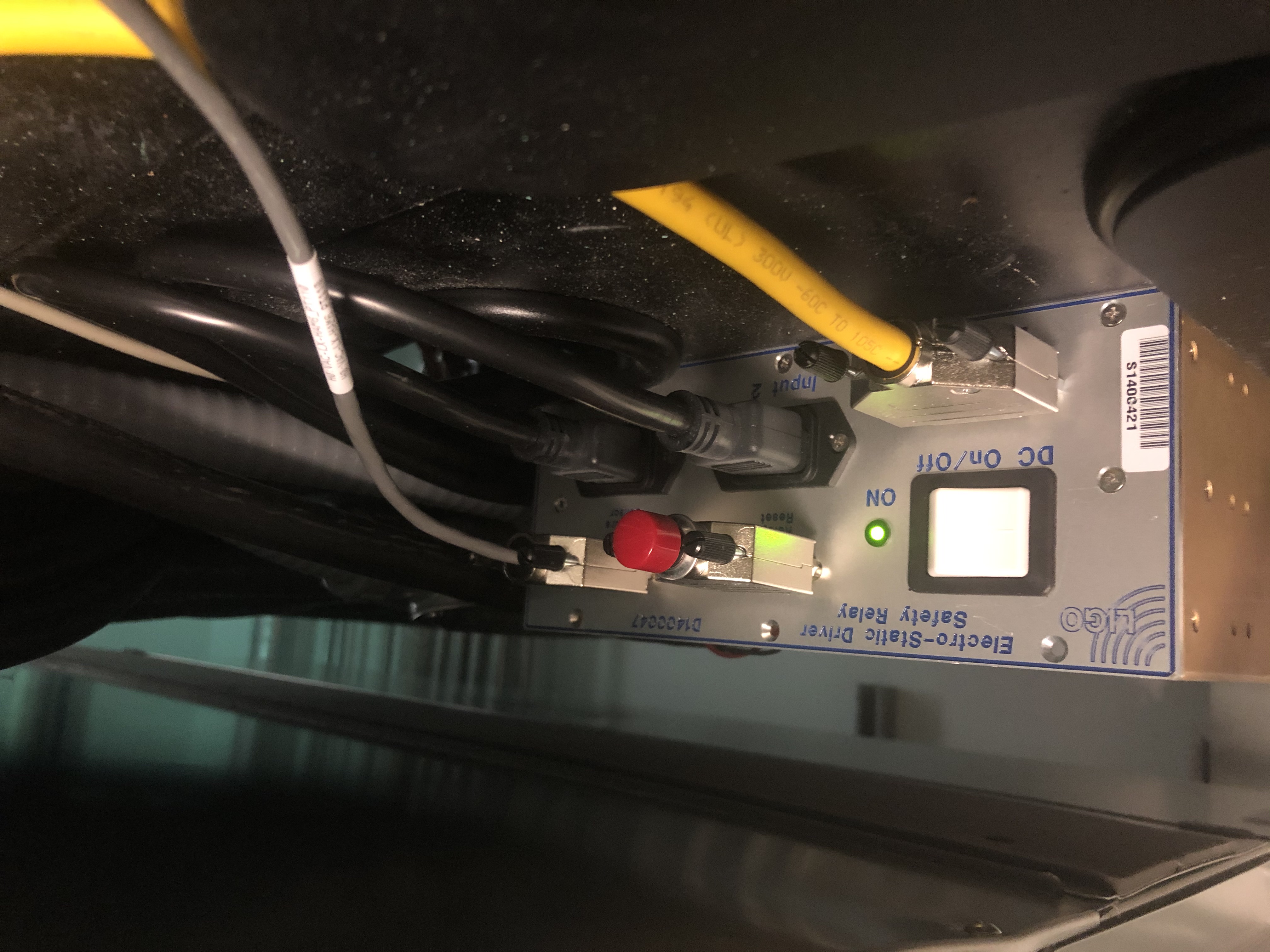
(B) IMG_2296.jpg -- the back of the High Voltage Interlock chassis located on top of the high voltage power supply rack ("C6"). Lights were green...
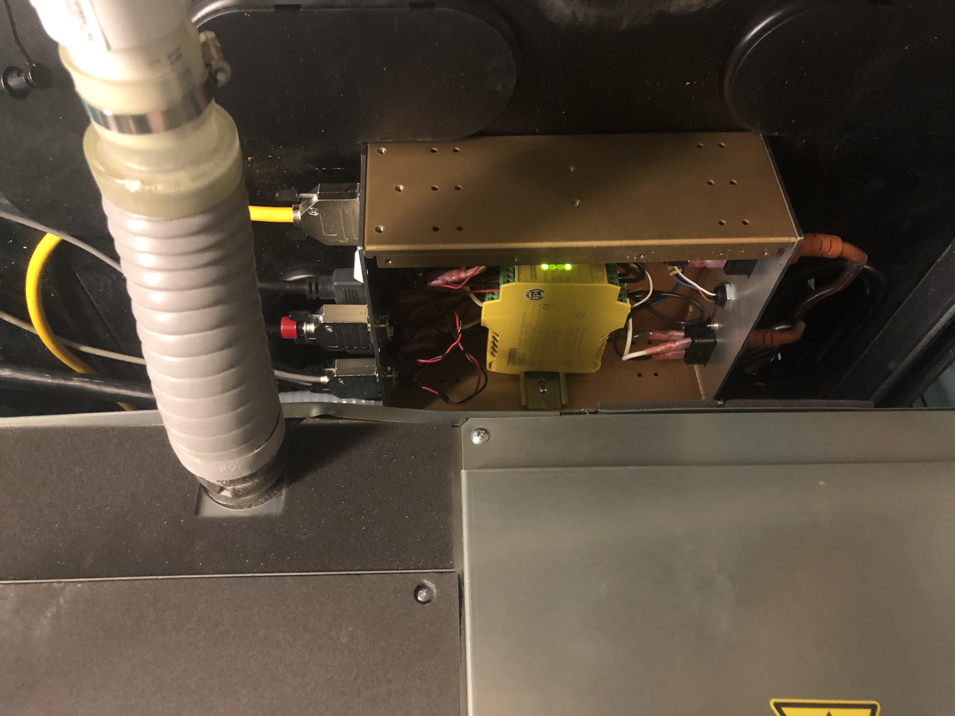
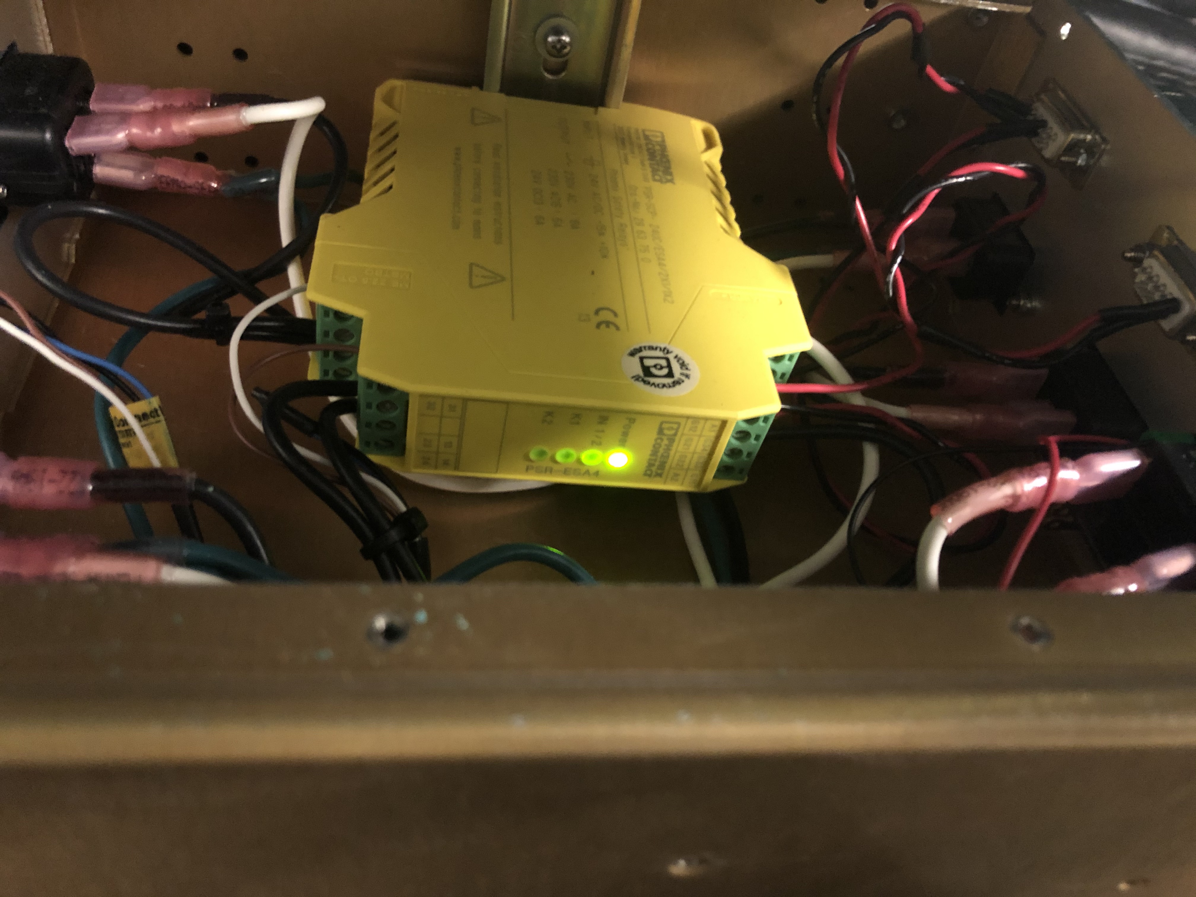
(C) IMG_2297.jpg -- A view inside the interlock chassis, showing the yellow beckhoff interlock module. This picture is before we power cycled the chassis -- step (7) from above -- and only on the "Power" and "K2" indicators were lit green on the interlock module.
(D) IMG_2298.jpg -- The interlock module after power cycling the chassis, (8). Now *only* the power light was green.
(E) IMG_2299.jpg -- This is a picture of the PT110 ion gage controller that Gerardo and I checked in the mechanical room, (9)
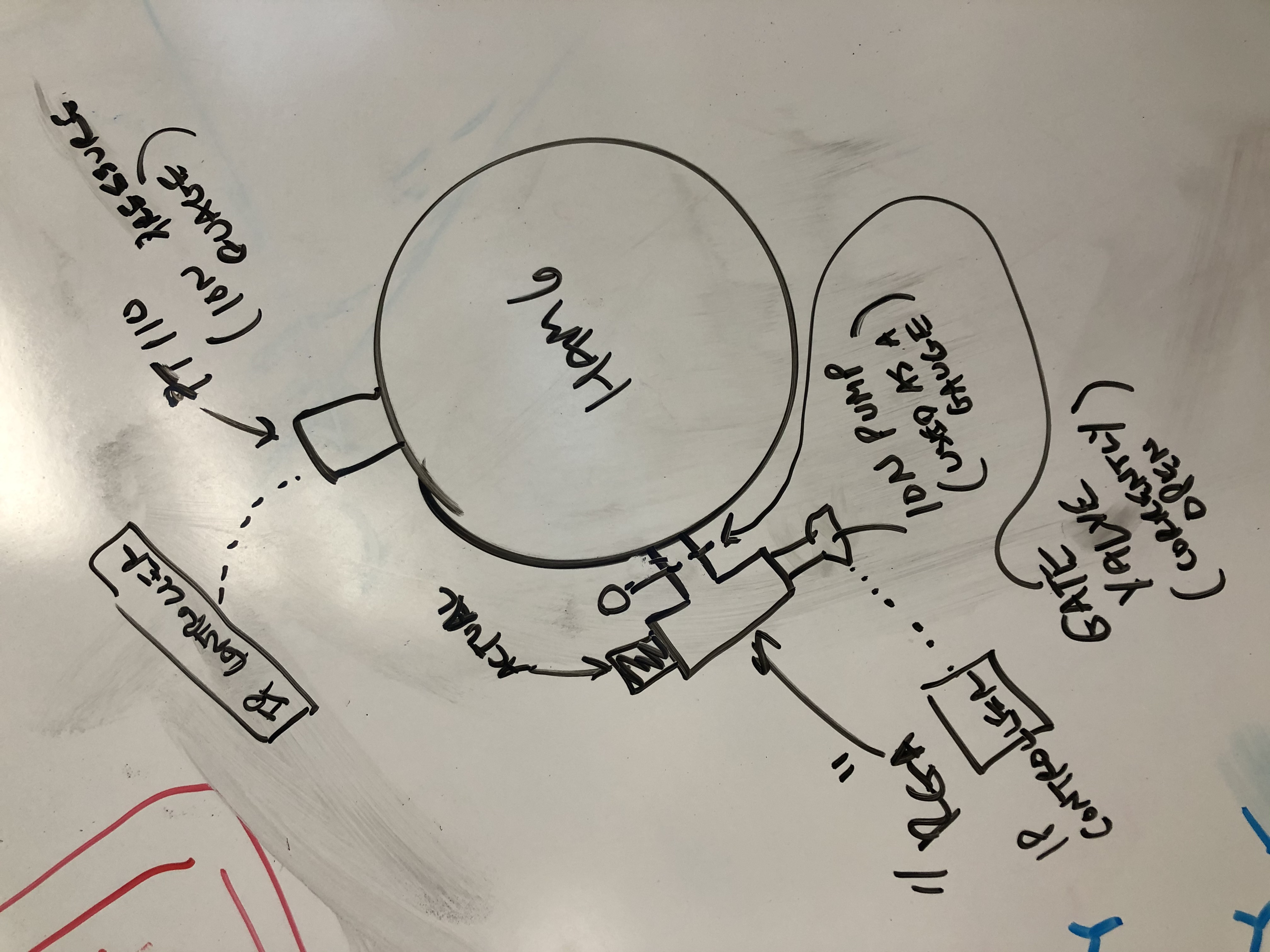
Here's a rough diagram of the vacuum pressure gauge system layout on HAM6 (I'm not sure it's complete, but it at least explains the two systems involved in this aLOG). The PT110 ion (pressure) gauge is a dedicated gauge measuring the pressure in HAM6. This is the nominal sensor signal for the high voltage interlock (I think). However, this sensor was replaced during the O3 break, and subsequently found to be noisy / glitchy, regularly, falsely, reporting pressures above the interlock threshold. This was only discovered just a few days before the end of the October break, so a temporary fix was rigged up with the RGA's ion pump controller -- see LHO aLOG 52775. The newly installed RGA, and the ion pump for the RGA, have been installed in on a T, behind a small gate valve that is currently open. Thus, making it a viable pressure sensor for the interlock. This is the same new RGA system whose cooling fan was turned off on Dec 18, when it drew attention as noisy during an LVEA sweep (see LHO aLOG 53963). It's this temporary system that failed today, and the interlock signal has been reverted to the PT110. I got *some* words from Richard that this is OK because since the October break, the PT110 signal has been cleaned up ... but I'll leave it to them to confirm via comment.
FRS Ticket #14013 filed.
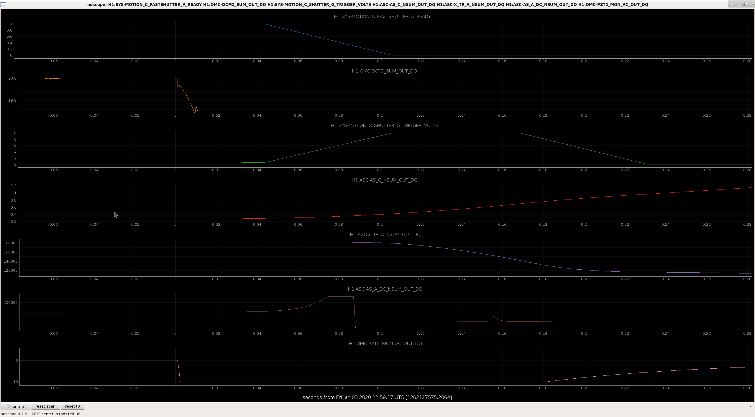
In the attached, loss of the OMC PZT2 HV at t~0 eventually kicked OMC and IFO out of lock.
Good to see that the fast shutter worked at t~0.09 even when HV is lost, as the fast action of the FS comes from the energy storage capacitor charged at 250V.
J. Kissel I've processed the most recent sensing function data from this morning (see LHO aLOG 54260), but now that I've finally obtained the ability to retrieve GDS computed time-dependent correction factors derived from the calibration lines, I want to compare these long term trends against the parameters derived from the occasional sweep that we do. It's still an open task to process the data from the comb of calibration lines during thermalization (i.e. the data from LHO aLOG 53951), so we won't address the low frequency end of the sensing function too much (where we believe the detuned spring frequency of the SRC is mixing with parasitic L2A2L). In this aLOG, I fit all of the O3B sensing function measurements via MCMC, limiting the MCMC fit frequency range to only be able 20 Hz (i..e above where the low-frequency nonsense is occuring). These are with individual scripts, like /ligo/svncommon/CalSVN/aligocalibration/trunk/Runs/O3/H1/Scripts/FullIFOSensingTFs/ process_sensingmeas_20200103.py Then, I enter those MCMC results for the relative optical gain change, \kappa_C, and the darm coupled cavity pole frequency, f_cc, in to /ligo/svncommon/CalSVN/aligocalibration/trunk/Common/pyDARM/src/ readHardcodedTDCFs.py (Note, I intentionally set f_s and Q_s to be 0 Hz and 1e-2, identical to the reference model, because -- even if the MCMC thinks there's a spring, I want to ignore it, and just leave it as an open systematic error.) Doing so, now, when I call the processing of the sensing functions indicating that it is *not* a reference measurement, then the data will be corrected for these TDCFs. The first two attachments show the difference between the uncorrected vs. corrected sensing function collection, showing how the collection of data clean up with the application of TDCFs. The third attachment shows how the sweep-computed TDCFs compare against the GDS computed, CAL-line-derived TDCFs of the course of O3B. Several interesting things in this collection of plots: (1) The Sweep TDCFs *roughly* track the CAL Line TDCFs, but disappointingly miss quite a few of the trends. I'm not sure I know what this means yet. As a check to make sure the MCMC fits were doing sensible things, I also looked at the collection of MCMC fits and parameter corner plots, which I attach 4th and 5th. *At least*, both TDCF calculations track the time period between 2019-12-04 to 2019-12-11 when we had trouble with the PSL rotation stage and we were sending less power in the the IMC (about 36W instead of 38W), and thus \kappa_C became closer to 1.0, because this was the power we were sending in on 2019-09-09 -- the reference model we're still using (and hope to update next week). (2) I still cannot trend PSL power channels, though, so I still don't have any clues as to what the ~1 month long hump between 2019-11-19 and 2019-12-13 of both f_cc and "f_s^2" (insert all the usual caveats that the GDS derived f_s^2 does not consider the parastic L2A2L coupling, so this number doesn't correspond to the model of a spring only thing, but it's all we've got for now). I haven't tried trending other things like IFO alignment (expect for times when we've performed an initial alignment, which don't appear to have any correlation), or thermal things. So -- no mysteries solved here, but a bunch of data has been processed, and we're starting to get all information on the same plot finally in order to form a game plan for how we'll handle all of this systematic error in the sensing function. The script that produces the TDCF trend is /ligo/svncommon/CalSVN/aligocalibration/trunk/Runs/O3/H1/Scripts/FullIFOSensingTFs/ plot_H1_GDS_TDCF_MinuteTrends_20200103.py
TITLE: 01/04 Day Shift: 16:00-00:00 UTC (08:00-16:00 PST), all times posted in UTC
STATE of H1: Lock Acquisition
INCOMING OPERATOR: Corey
SHIFT SUMMARY:
LOG:
current status
TITLE: 01/04 EVE Shift: 0:00-08:00 UTC (16:00-0:00 PST), all times posted in UTC
STATE of H1: Not Locked
OUTGOING OPERATOR: Cheryl
CURRENT ENVIRONMENT:
SEI_CONF state: WINDY
Wind: -
Primary useism: -
Secondary useism: -
Summary:
H1 just had a lockloss, which looks like it was due to a High Voltage trip at HAM6 (which trips due to Vacuum pressure at HAM6). Several people have been investigating & trying to restore via instructions from Richard, but have not been able to untrip the HAM6 Hight Voltage. Richard M is now driving out.
This lockloss was at 22:59 UTC & since its fairly confirmed to be due to a hardware issue, we should be marked DOWN for CORRECTIVE MAINTENANCE from that time (vs about 0:25 when we took OBSERVATORY MODE to that state).
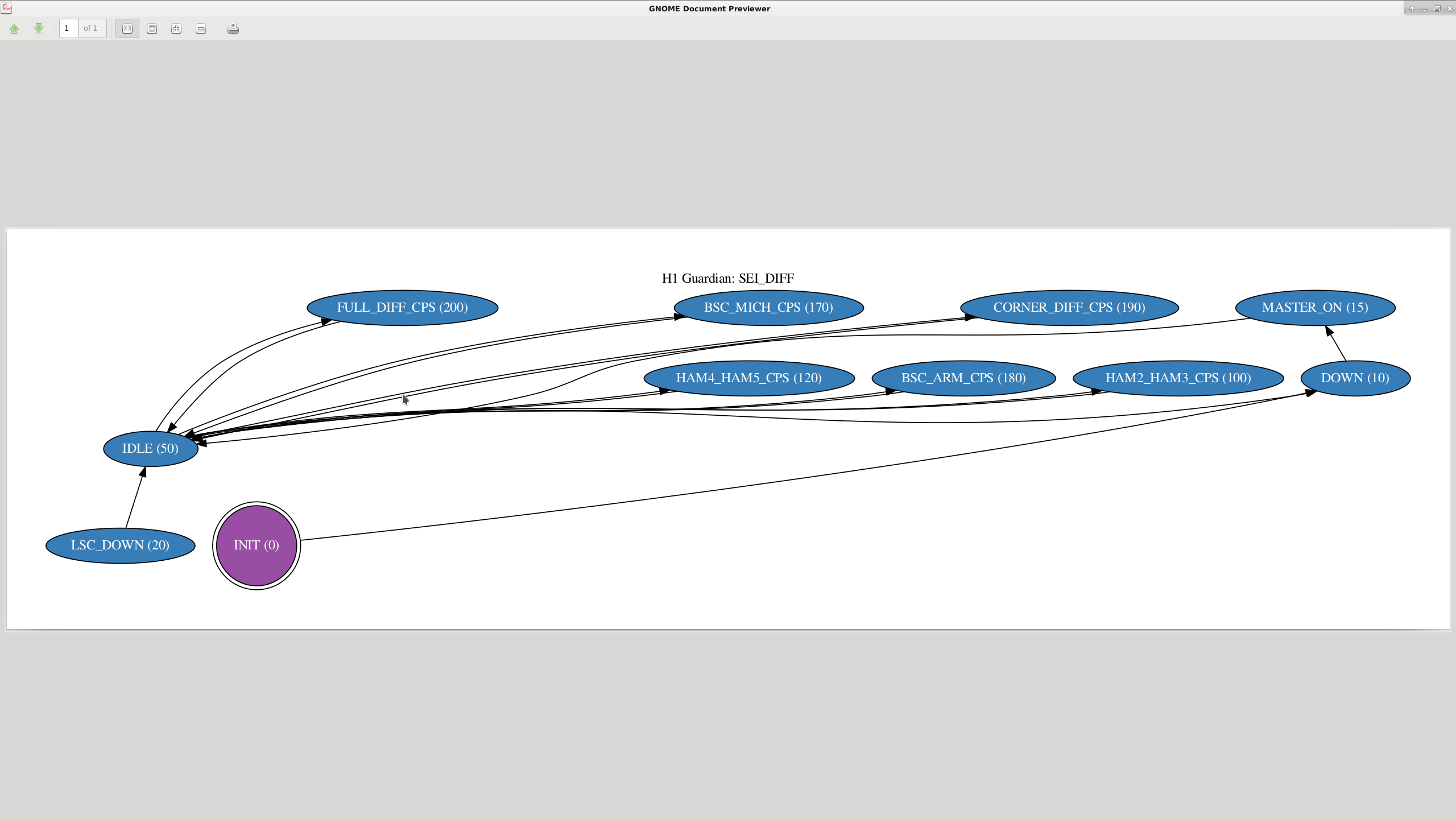
During my test earlier, I found that if SEI_DIFF was requested to go from one state to another, it wouldn't transition correctly. This was because we originally wrote it such that we could turn different parts on separately, and requesting a new branch wouldn't affect the other parts. That's not the way we've been using it, mostly turning it off or using only the corner CPS diff when the microseism is high, and before the break we ran CPS DIFF down the arms as well when microseism was low.
I've changed the edges now, such that requesting a new state runs SEI_DIFF to down, which turns the control bit off, then it goes through MASTER_ON, which resets gains and some other stuff and then restores the control bit allowing output, then the new state turns on filters, sets paths and turns on the correct output gains. This lets you go from one state to another and only the paths requested in that state will be turned on.
First screenshot is the old arrangement, where IDLE was the hub state. Second screenshot shows the graph now, where every state goes the DOWN, then MASTER_ON, then to the requested state.
Turned off the SEI_DIFF control bit at 1262121606, this turns off the output to all chambers at once. Because this doesn't knock us out of OBSERVE, and shouldn't affect observational data. In 20 minutes or so, I will turn on the full differential cps including the arms, which will likely take us out of OBSERVE, briefly. Again, shouldn't affect observational data. Will the time here. When that test has run, we'll make a decision then about what state to leave the CPS differential in.
Turned SEI_DIFF to FULL_DIFF_CPS at 1262123072, actually started a bit before that, but because of the path I took, the control bit had to be flipped manually and it took a couple minutes to realize. Given the environment, we can leave this on until the microseism comes back up.
The SEI_DIFF guardian needs some thinking to get the transitions from one state to another to work a little better. Currently, if we wanted to go from, say FULL_DIFF_CPS to CORNER_DIFF_CPS, the best procedure would be to to request down, the request the desired state.
The soon to be made change to LHO calibration is planned for next Wednesday (20200108).
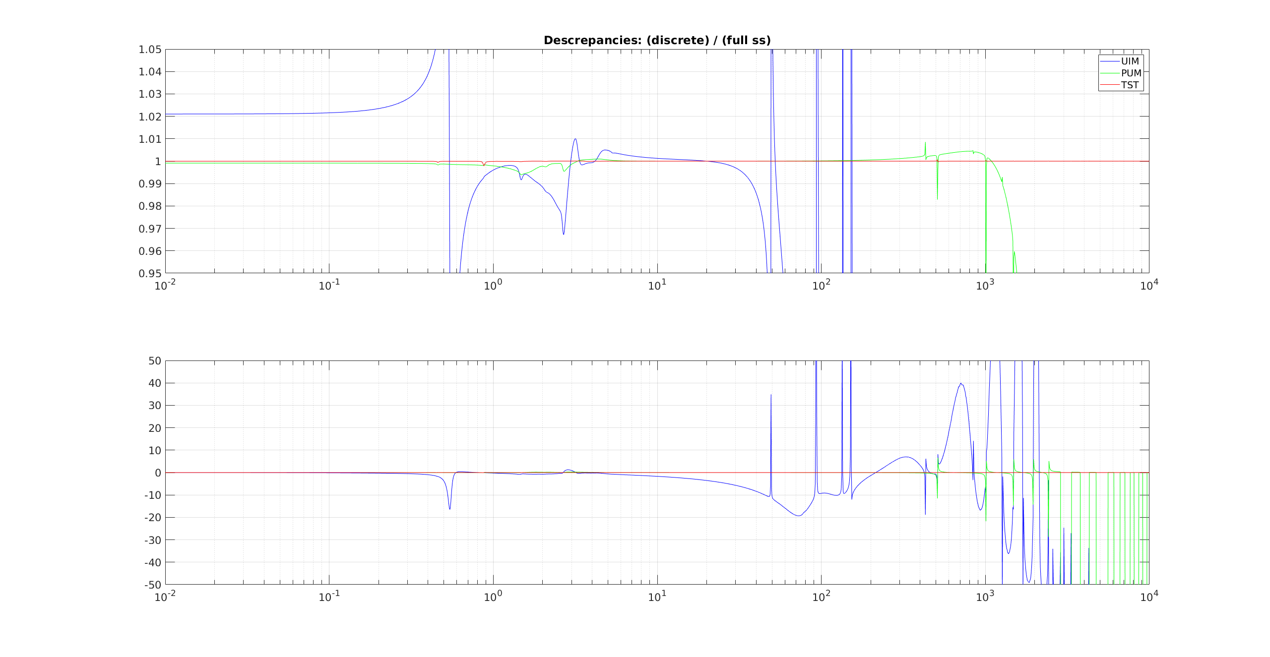
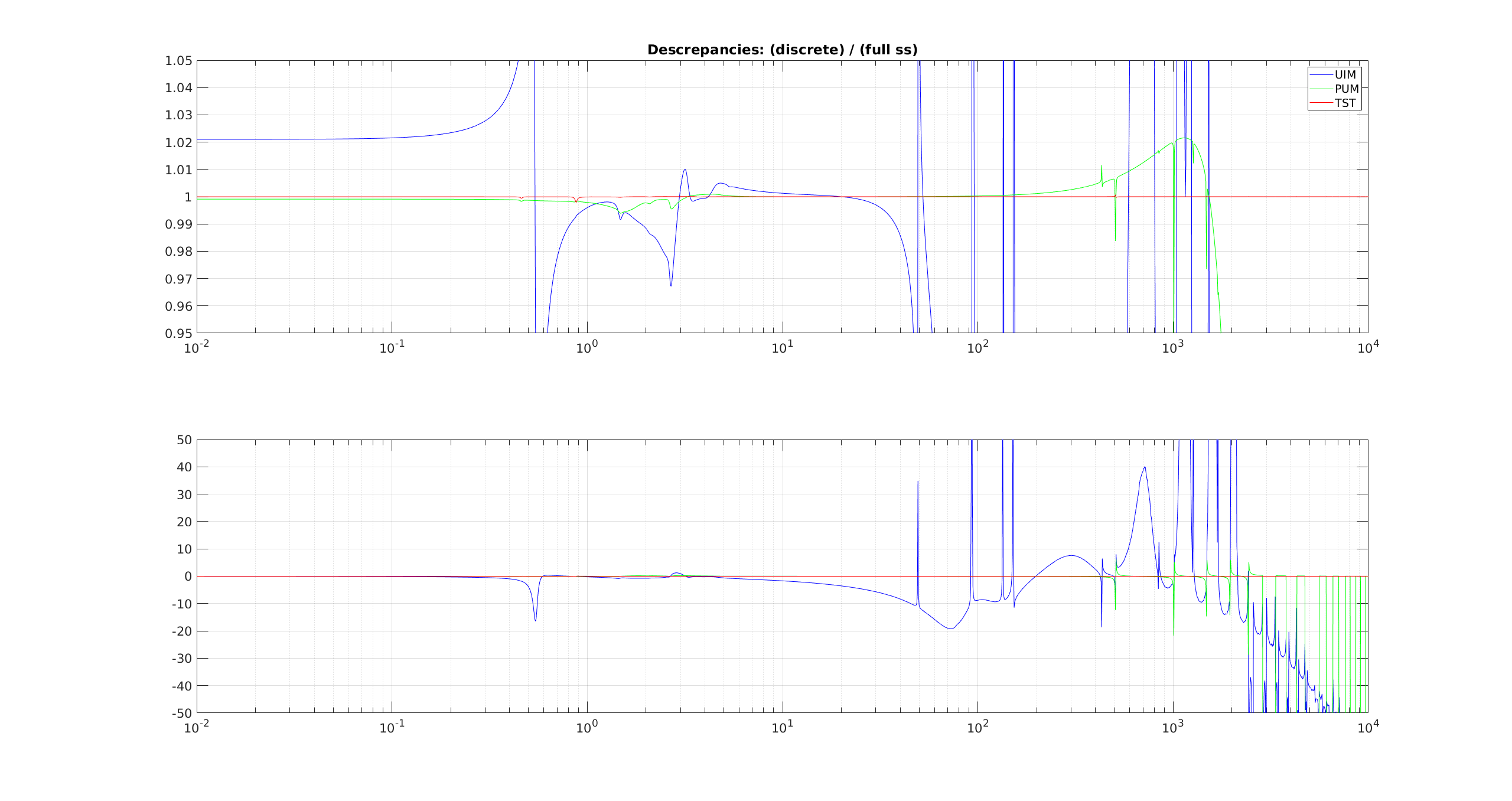
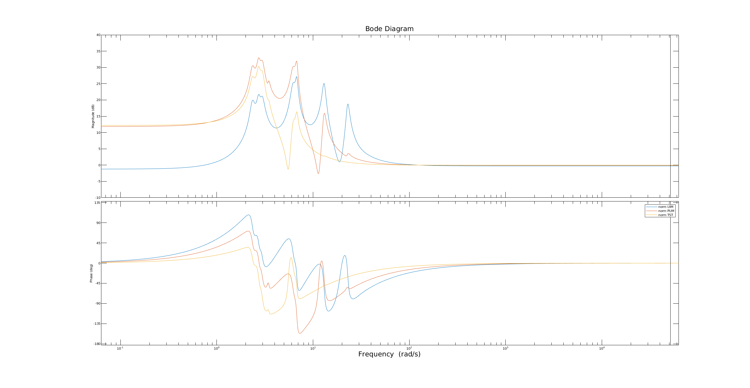
As a follow up to what the newly modeled UIM dynamics will change I have generated a couple more plots. Previously I looked at how the pyDARM calibration will change with the updated TF (the comment in a related report), highlighting the improvements to calibration, and how they line up with known discrepancies between DELTAL and Pcal.
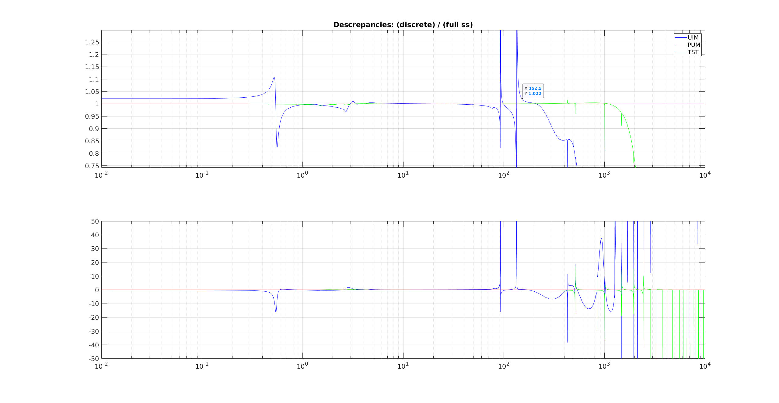
Now I look at the difference between the new front end, foton filterbank, and the pyDARM calibration contributions to R (2020-01-03_H1_Rfoton_new_over_Rpydarm_new.pdf) - here you see that I am missing two features, one at ~90 Hz and at 134 Hz (you can see these in the comment to the related report as well).
Finally I look at the total change in the front end, as a change in contribution to R (2020-01-03_H1_Rfoton_new_over_Rfoton_old.pdf) . This is equivalent to the change in calibration on the DELTAL.
There is quite a lot of alterations at lower frequencies (<40) in the comparison of contributions from the foton filters. Other than the testmass correction and new 50-150Hz UIM features, nothing is supposed to impact these low frequencies. I suspect the reason is that in propagating the the SUSmodels (L1, L2 and L3 stage, i.e. the UIM, PUM and TST stages) to the foton filterbanks, and I optimising the minreal functions of matlab to keep absoluteley as many poles and zeros as I can get away with. For example the UIM stage (where I took the most time and care), is comprised of (ignoring the 1/f^6 filter bank and the gain only bank) 3 filter banks of 10, 10, and 9 Second Order Sections (the max allowed in foton is 10). I used this philosophy for the lower stages also - and I suspect the low frequency parts of the SUSmodels are better represented in this iteration of the filter - giving rise to corrective changes below 40Hz in 2020-01-03_H1_Rfoton_new_over_Rfoton_old.pdf.
I have prepeared a new parameter file:
/ligo/svncommon/CalSVN/aligocalibration/trunk/Runs/O3/H1/params/ modelparams_H1_20200103.py
Which reference to updated H1susdata file:
/ligo/svncommon/CalSVN/aligocalibration/trunk/Common/pyDARM/matlab_scripts/ 20200103_H1_03_susdata.mat
I will write a bash script next week that automates the generation of that .mat file, since presently it is a two step process, between matlab and python
J. Kissel
I've gathered a new, complete, set of calibration measurements today. This is the first complete set within the same lock stretch since 2019-12-04, given that we've either elected not to measure the actuator, or we've been plagued by earthquakes and computer problems. I intend to use this data set for the creation of a new calibration model parameter set, hopefully to be installed next Wednesday (01/08).
Analysis to come, but here are the files:
/ligo/svncommon/CalSVN/aligocalibration/trunk/Runs/O3/H1/Measurements/FullIFOActuationTFs/
2020-01-03_H1SUSETMX_L1_iEXC2DARM_8min.xml
2020-01-03_H1SUSETMX_L1_PCAL2DARM_5min.xml
2020-01-03_H1SUSETMX_L2_iEXC2DARM_12min.xml
2020-01-03_H1SUSETMX_L2_PCAL2DARM_6min.xml
2020-01-03_H1SUSETMX_L3_iEXC2DARM_12min.xml
2020-01-03_H1SUSETMX_L3_PCAL2DARM_6min.xml
/ligo/svncommon/CalSVN/aligocalibration/trunk/Runs/O3/H1/Measurements/FullIFOSensingTFs/
2020-01-03_H1_DARM_OLGTF_LF_SS_5to1100Hz_15min.xml
2020-01-03_H1_PCALY2DARMTF_BB_3min.xml
2020-01-03_H1_PCALY2DARMTF_LF_SS_5t1100Hz_10min.xml
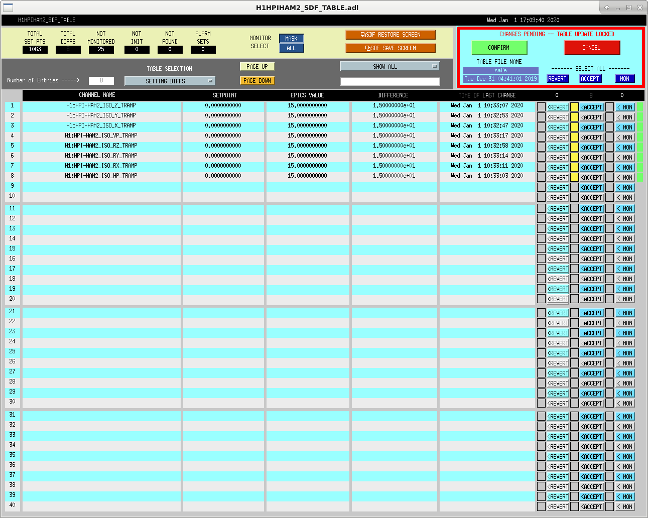
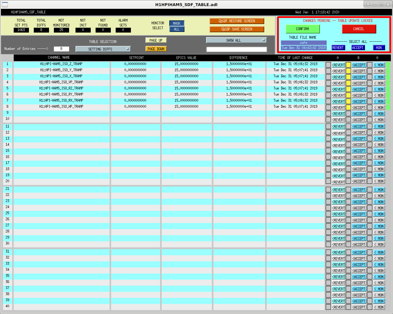
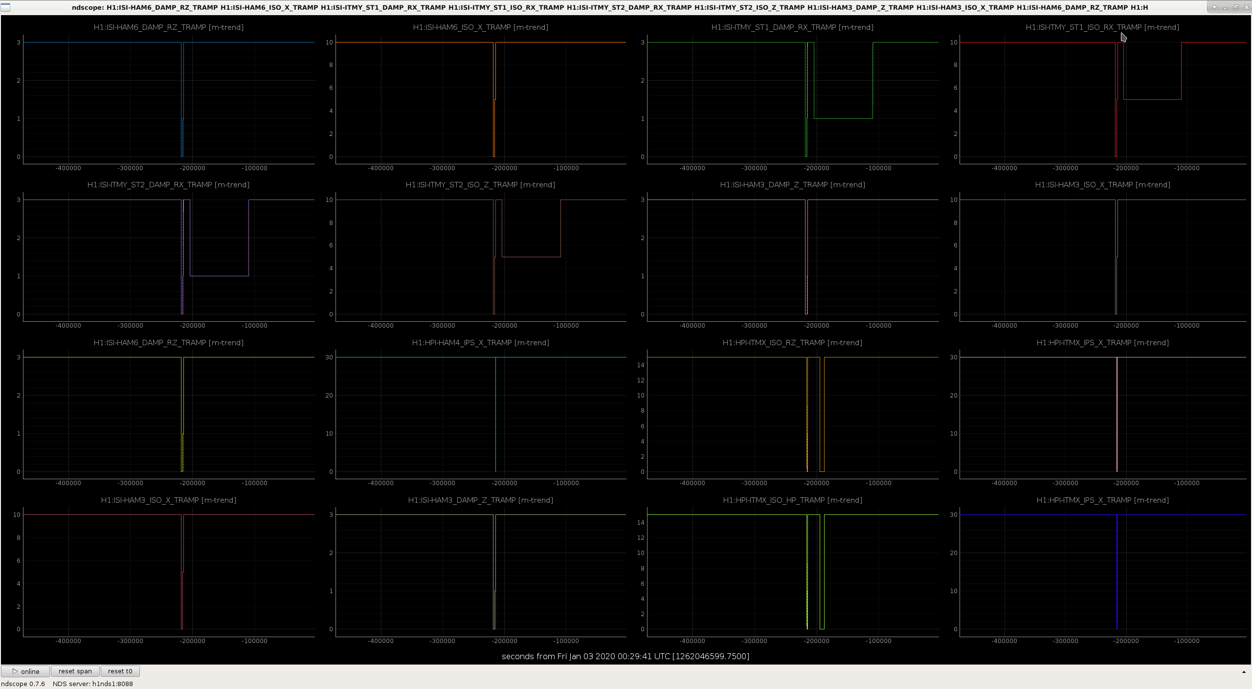
Attached are the TRAMP changes I accepted in SDF yesterday. Before accepting these, I ran a matlab script to look for the values 7 days prior and 14 days prior, and when those agreed with the current values, I then accepted them in SDF. These include TRAMP SEI values for ITMX, ITMY, BS, HAM1, HAM2, HAM3, HAM4, HAM5, and HAM6. Attached screenshots show most, but not all SEI HEPI and ISI TRAMP values that were restored. The overall list is:
These are a result of an unusual event, at an inopertune time, and now, experienced gained.
All of these chambers (unless I've missed something) had their safe.snap-s selected when these screenshots were taken, not their OBSERVE.snap-s, that's why these SDF diffs came up. Unsure if this will affect the chambers next time they are restarted, certainly having the BSC st1 l4c feedforward outputs turned on when the model is restarted isn't ideal. There maybe other issues.
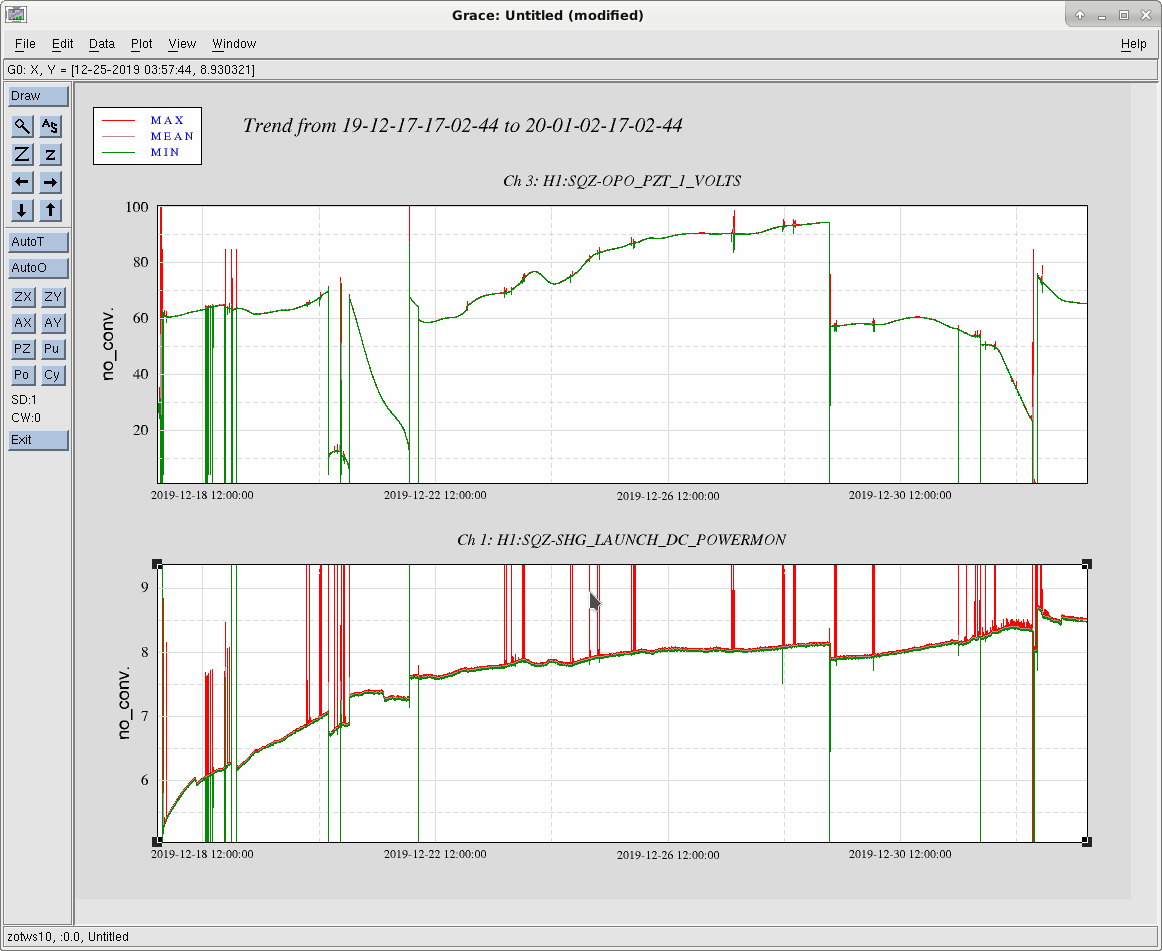
The initial degradation seems to have slowed down. Initially we needed 5.3mW at launch, but within the first 4 days this increased to ~7.5mW. Currently we need ~8.5mW of green pump light to mainatain the OPO intra-cavity power.
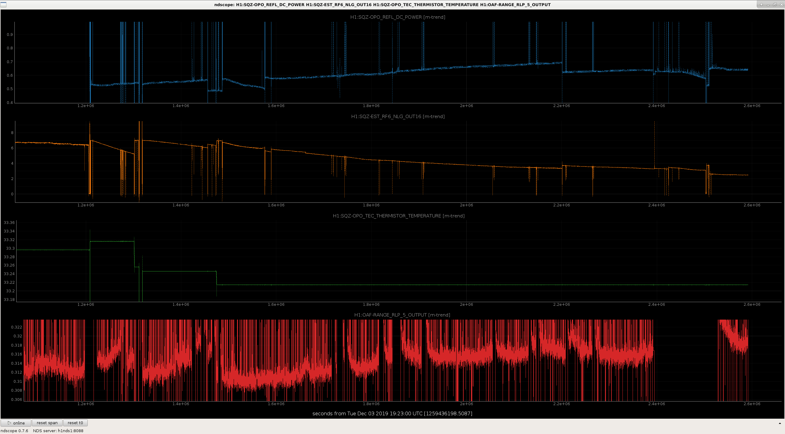
Here is a plot that shows that as the crystal absorption has increased, (roughly shown by the increase in the reflected power since the transmitted power is in loop), the nonlinear gain has dropped, and the DARM noise from 100-450 Hz, shown by OAF RLP 5 has gotten worse. In the first few days after the crystal move, we adjusted the crystal temperature set point to compensate for the increased local heating from absorption, which recovered the NLG. We probably need to do this again.
We adjusted the crystal temperature using the seed while the IFO was relocking. The nonlinear gain is now 2.7
H1 lost lock right after the SQZ BDV was closed for the above mentioned adjustment (thus "while the IFO was relocking").
After the IFO relocked but before we started injecting squeezing I checked the "dark" offsets of AS_A_RF42 and AS_B_RF42 (which is not really "dark" dark, it's "full IFO without SQZ" dark) we set last year (alog 54013) to see if they changed, and they didn't.
Since the offset comes from IFO light though nobody knows why, another question is if these change while the IFO is thermalizing.
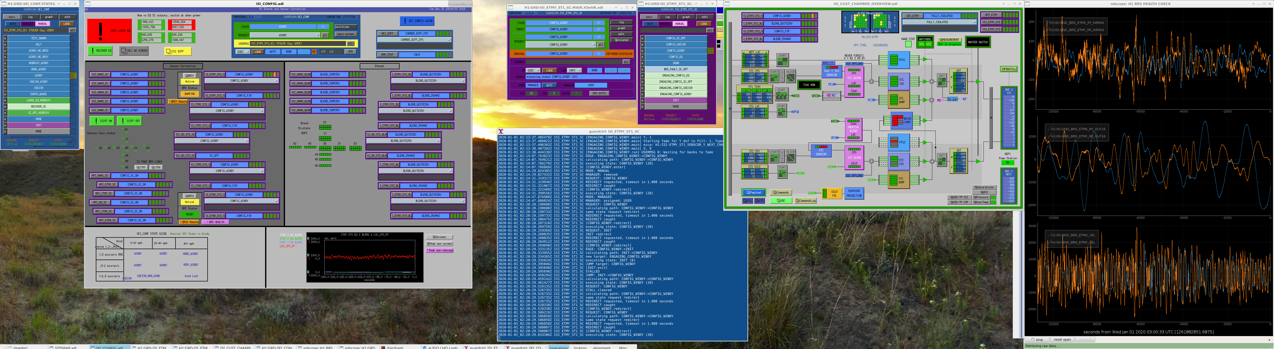
Decided to take SEI_CONF to the nominal WINDY state, but while there, notice that it has a FALSE state (i.e. orange box) for the NOMINAL box. See attached screenshot with all suspects involved.
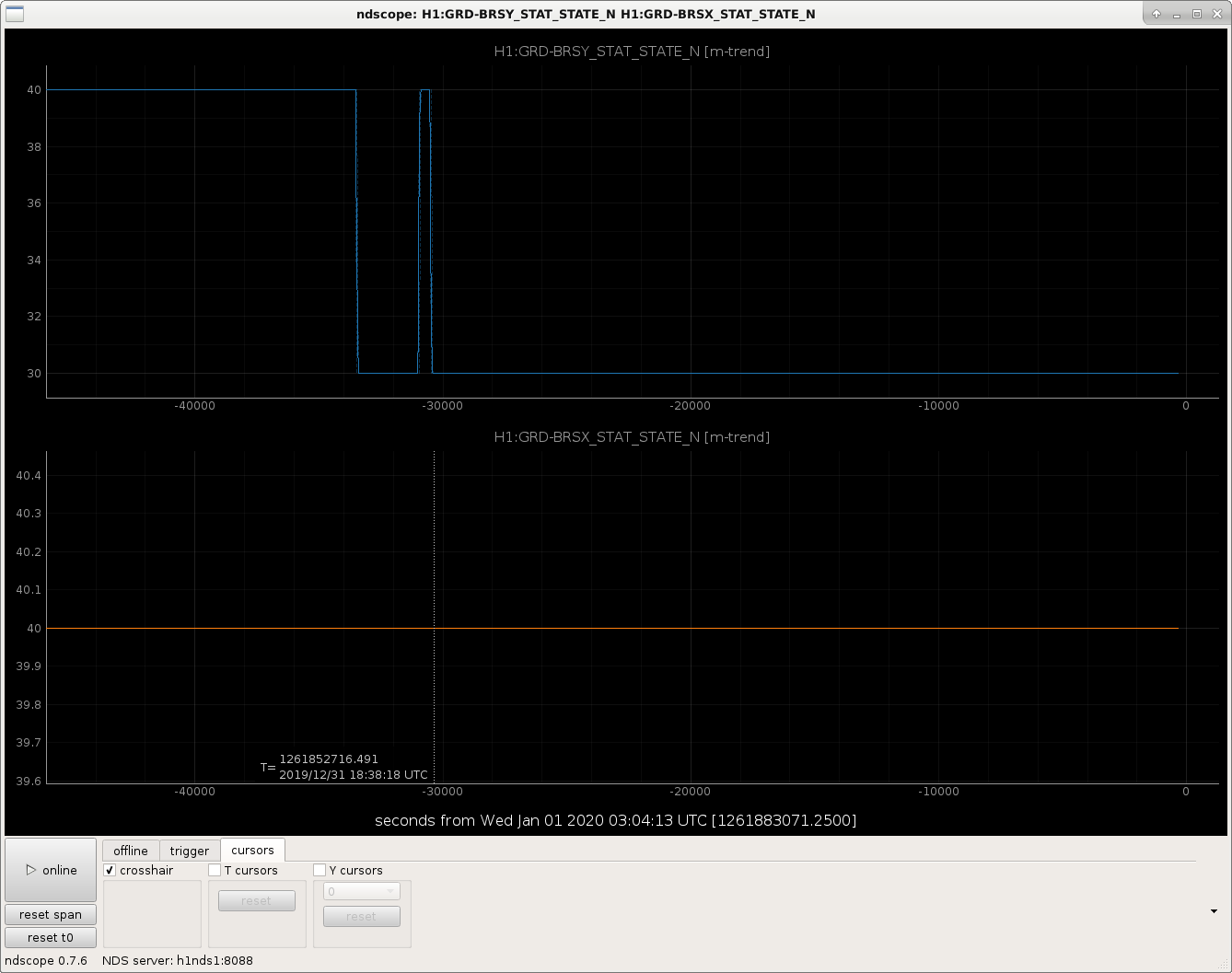
My guess would be that maybe it would be related to the BRSy Status being in the DAMPING state (N=30). I trended this channel (H1:GRD-BRSY_STAT_STATE_N), and it's been in this state since 10:37am earlier today. Maybe we need the winds to die down some more for it to get back to the READY (N = 40) state? 2nd Attachment is the last 12-14hrs showing BRSy switching to Damping for the last ~9hrs.
Texted Jim about this and he said we look normal, so will continue on and keep an eye on this.
The reason that SEI_CONF was FALSE was because someone had set themselves as the manager for ISI_ETMY_ST1_SC. If you look at the user message for SEI_CONF in the screenshot, it says "ISI_ETMY_ST1_SC: STOLEN (by:USER)".
As a reminder: Clicking the "MANAGE" button will make you the manager of the node, it will not give mangement back to the orginal manger.
I have prepared an update to the H1CALCS filterbank, for the L1,L2,L3 stages for ETMX and ETMY - as LLO did last month.
The changes incorporate:
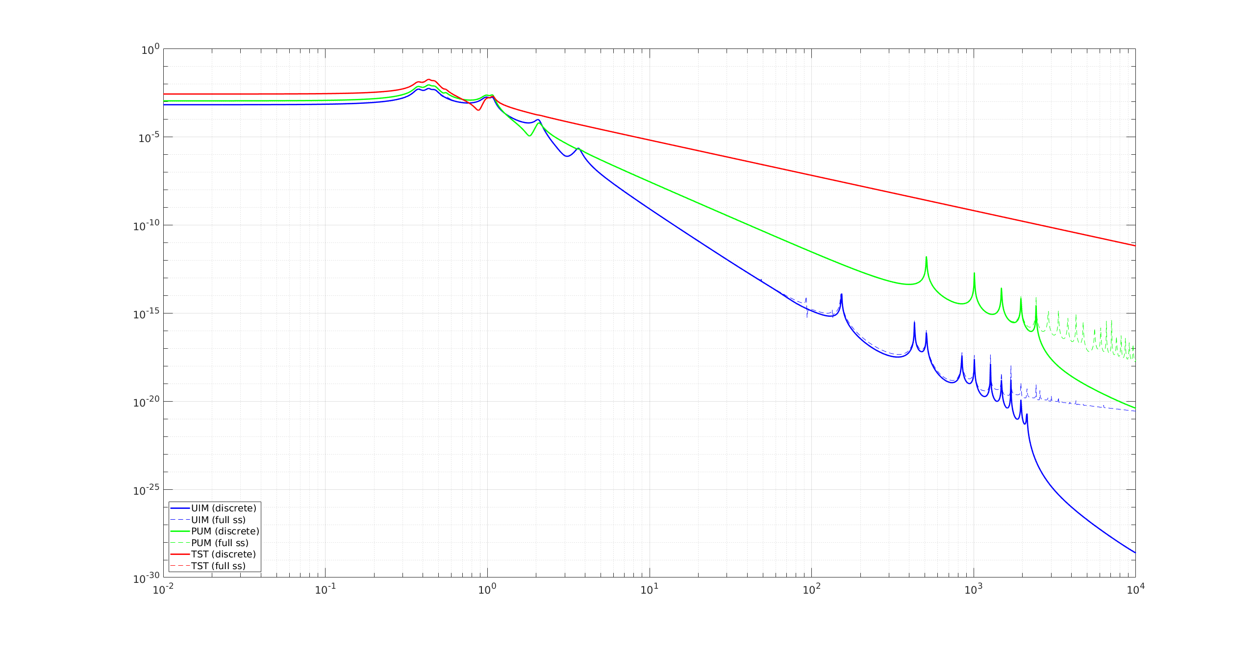
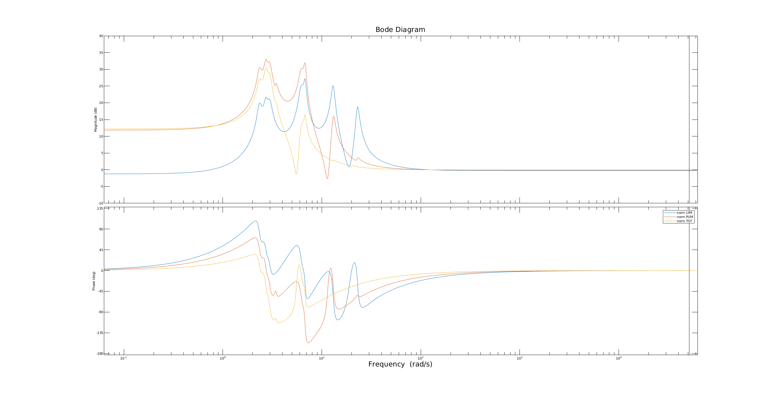
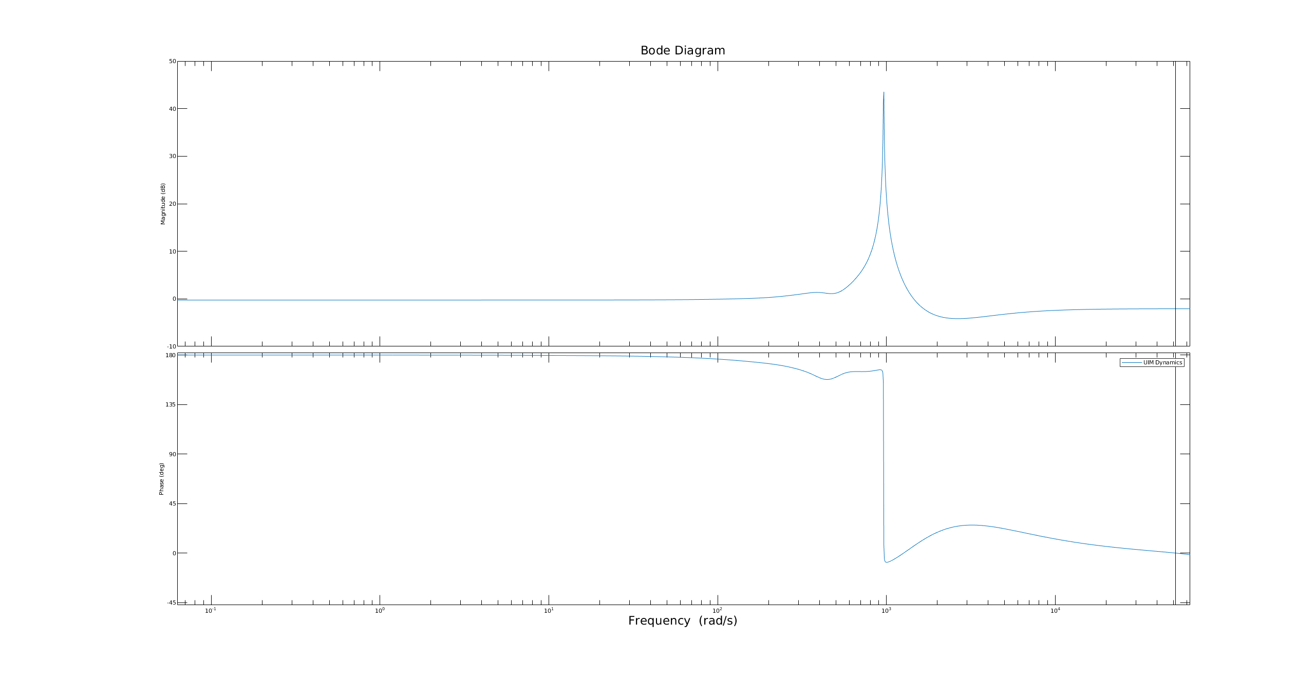
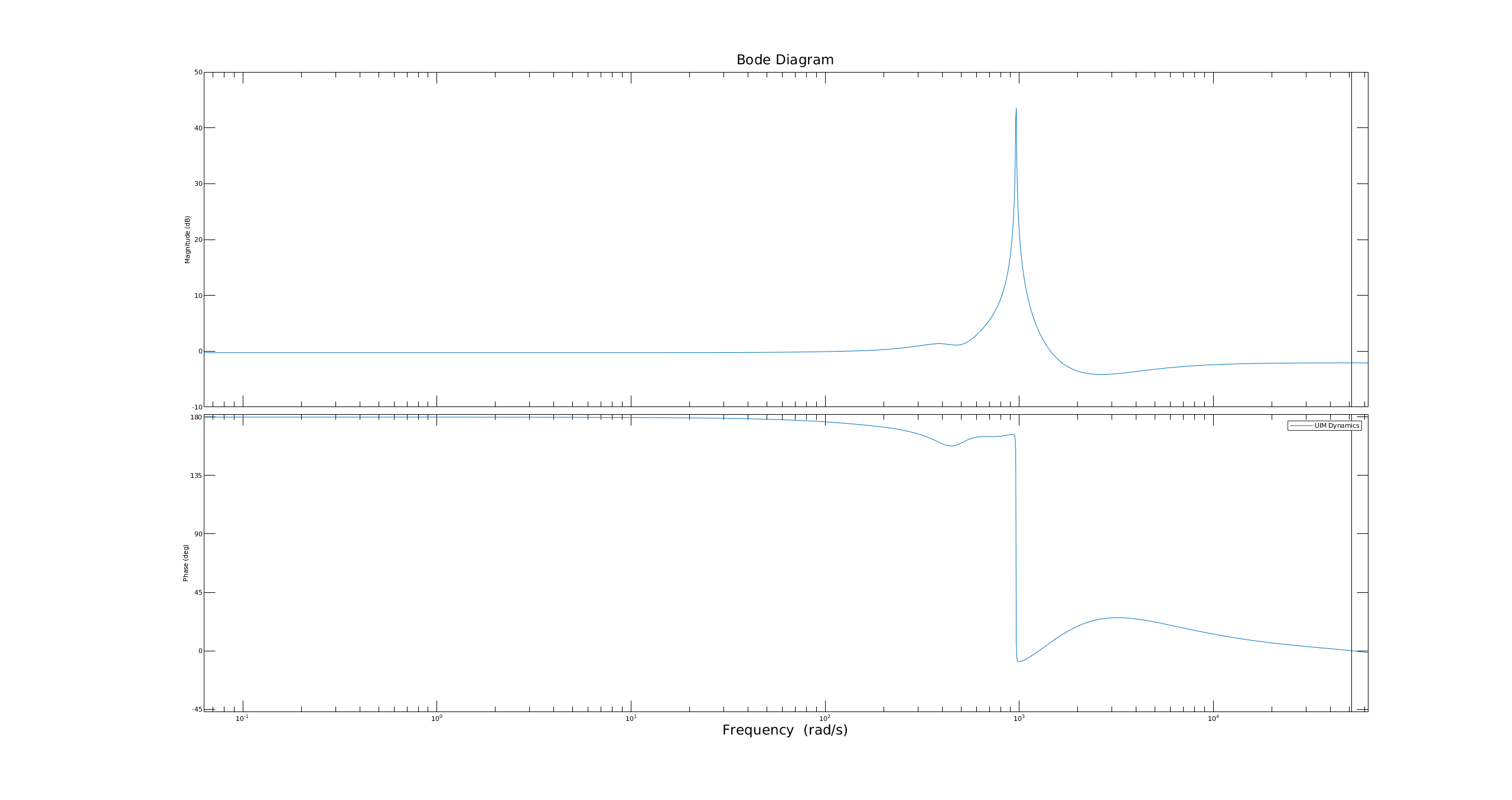
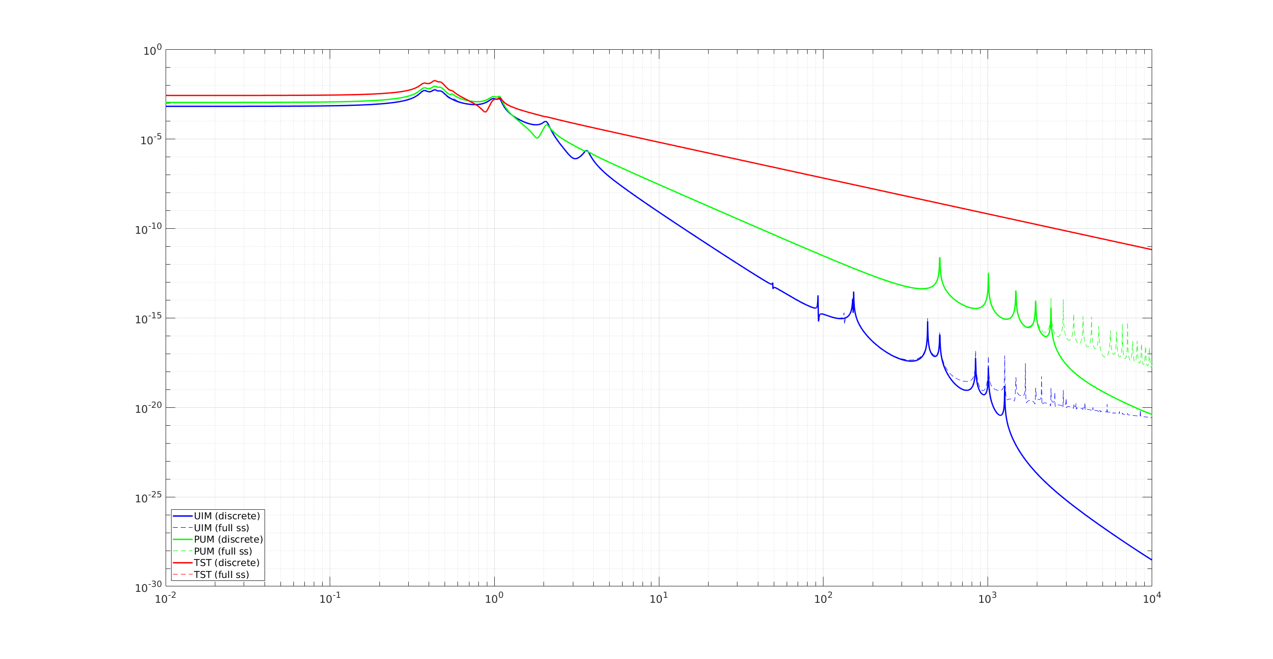
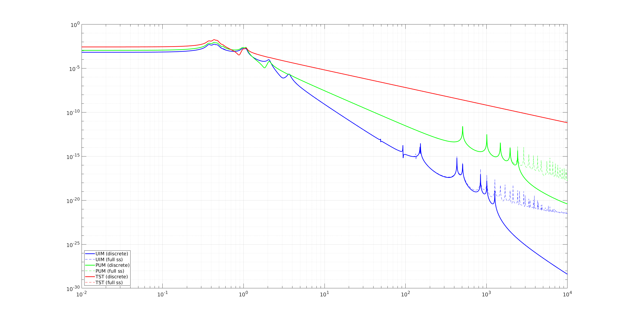
I have included a plot of what the new filter for the uim will look like in foton. In the minimum realization step of simplifying this new feature of the model to be foton friendly, a lot of features were cut away, and we're basically left with a single feature at 152 Hz.
If there is some downtime today (like an earthquake from Paraguay), I will be implementing this update, and enabling the new uim filter in the frontend.
Turns out other changes need to be made in parallel with this, so this will have to wait until the new year.
I made some futher improvements the new new foton transfer functions to better model the UIM changes I had added. See attached plots