General:
-Safety: Watch for deer, aggressive drivers
-Site Weekly this week, film crew onsite today
-Lee and Kentaro visiting
Tuesday maintenance:
-PT 110 Diagnostics, GV1/GV2 soft close
-Fix EY HWS beam path
-PEM coil work at all stations
-Scaffolding removal if VAC work is completed successfully
-HAM2 door cover install
-BRS heater work
-SQZ Beckhoff restart
-EX NCAL work ongoing
-EX/EY ISI model reboot
-Wind fence work ongoing
-HAM2 camera work (ToO)
Lee, Kentaro, Nutsinee, Daniel
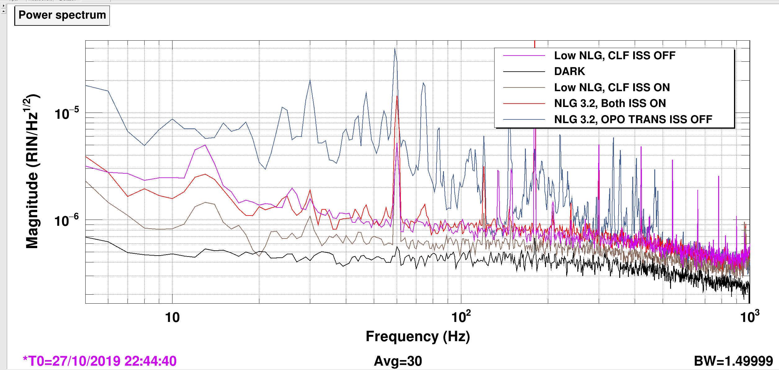
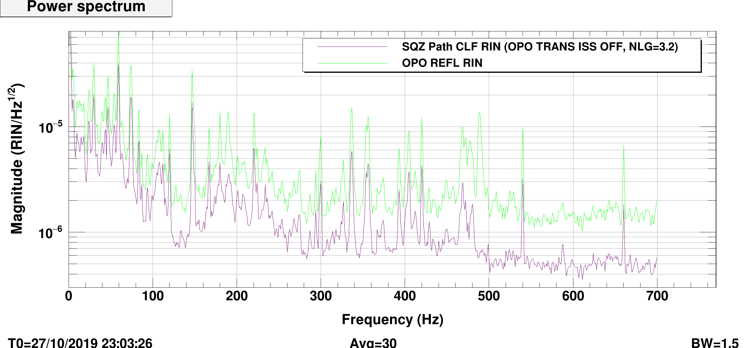
The A+ filter cavity will require more CLF light and demand a stronger requirement on the RIN of the CLF light to not inject noise in DARM. The requirement isn't particularly tough at 5e-5 RIN/rtHz of the CLF light carried with the squeezer field (T1800447-v6 figure 13). The laser already meets the requirement in broadband, but has lines and beam jitter noise that can take it above. Mark upgraded and installed an ISS for the 532 OPO pump as well as one for the CLF itself. Today we studied if the CLF on the SQZ path is witnessed to meet requirements with and without the new ISS's.
Bottom line is that the ISS's do help, and can meet the requirements with them even if we want to turn up the CLF more than needed. As it turns out, the pump RIN is the more important one, as the pump seems to get more noise on it going through the SHG, fiber and OPO. The OPO-transmission signal that the ISS servo feeds back to is the proper witness, but has a very low light level due to the small transmissivity at 532 of OPO-M2.
Setup:
CLF_SQZ_PATH_RIN.png shows the RIN measured from the homodyne at different configurations.
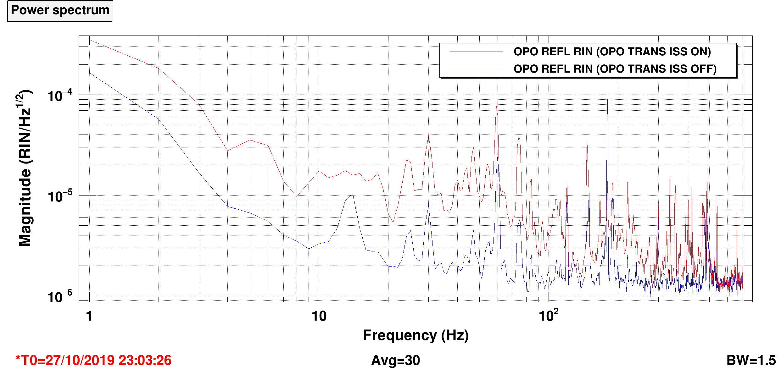
PUMP_RIN_XFER.png uses the OPO 532 REFL as a witness for the RIN during the ISS-OFF time (OPO 532 TRANS was not properly saved). It shows the direct imprint into the CLF RIN with a gain of 0.4. I have an elaborate OPO model for the filter cavity that manages to predict this factor of 0.4 at the operating NLG of 3.2: dNLG.pdf. As we increase the NLG, the RIN2RIN coupling will increase, but not severely.
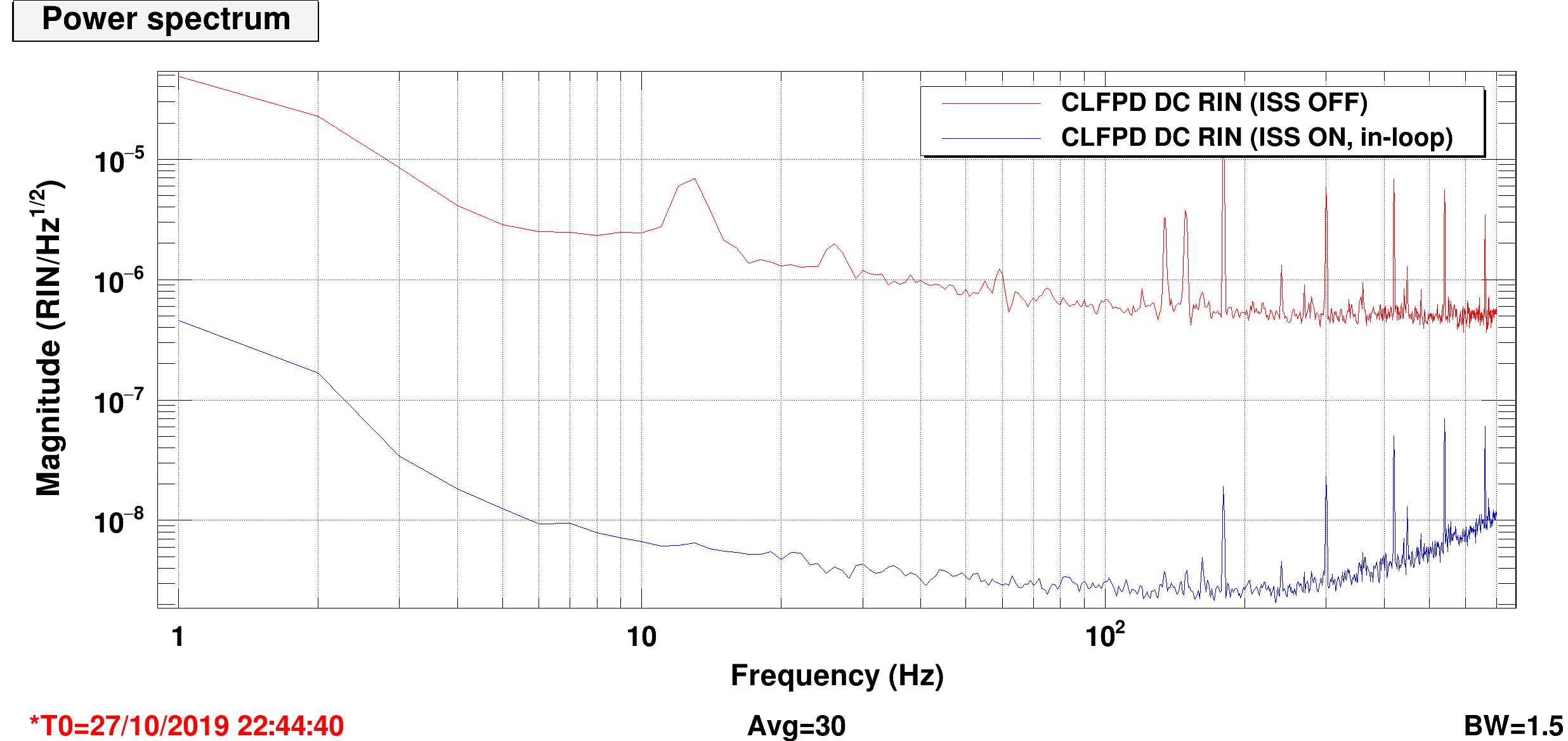
CLFRINONOFF.png shows the in-loop CLFPD DC with and without the servo. The OFF-level agrees with the level expected of the laser + some acoustic excesses.
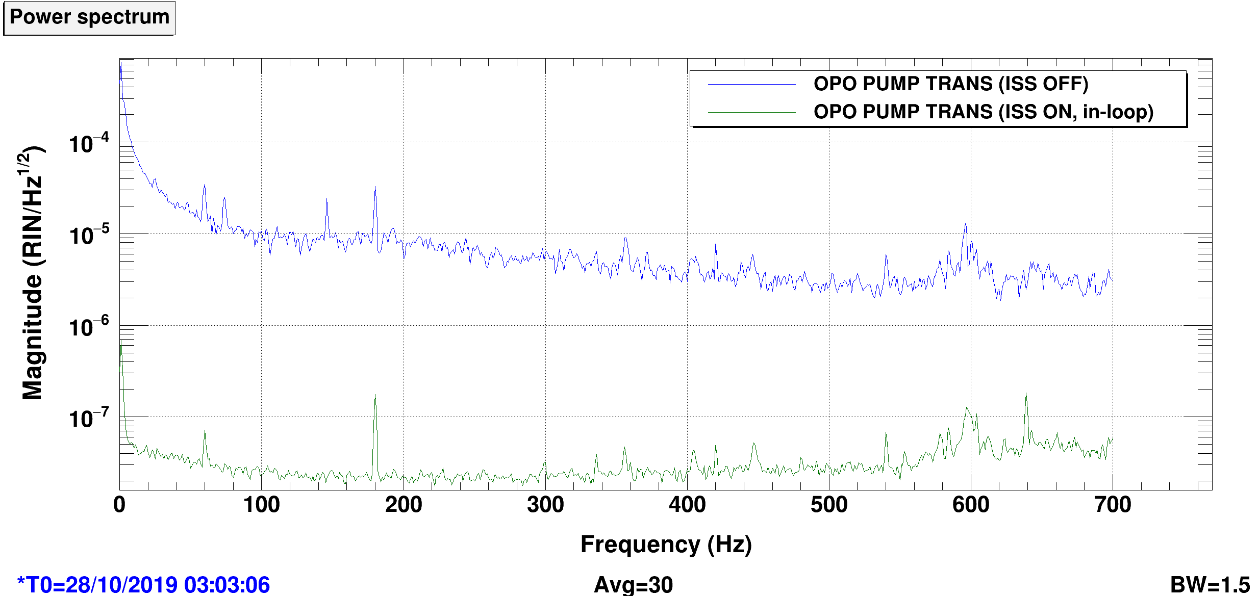
OPO_TRANS_RIN.png shows the pump RIN of the in-loop trans PD with the servo on and off. When it is off, the level corresponds roughly to the shot-noise of a 1uW 532 beam, so the diode doesn't seem to be dark-noise limited, but the sensitivity is still pretty bad.
OPO_REFL_WITNESS.png shows that with the 532 TRANS servo on and off, the REFL does not show the same reduction. While REFL has more light and lower sensing noise than TRANS, the excess shown here while the TRANS-ISS is running indicates that REFL will indeed be a poor witness to stabilize the circulating power. There must be beam jitter noise or other cavity noise driving the difference between the two.
Ops Shift Transition: 10/28/2019, Day Shift 15:00 – 23:00 (08:00-16:00) - UTC (PT)
State of H1: Planned Engineering
Intent Bit: Commissioning
Weather: 0-5 mph wind
Primary 0.03 – 0.1Hz: 0.01 um/s
Secondary 0.1 – 0.3Hz: 0.2 um/s
Outgoing Operator: None
Quick Summary: Sheila is in the process of locking the IFO, at TRANSITION_FROM_ETMX
Stefan and Varun measured the SRC gouy phase at LHO to be higher than design.
LHO single pass gouy phase measurement is 25.3 +- 1.8 degrees.
LLO single pass gouy phase measurement is 21.3 +- 0.3 degrees.
I modeled the nominal SRC cavity, as has been done many times before, and got 23.5 degrees of single pass gouy phase.
optics_move_vs_single_pass_SRC_gouy_phase.pdf shows that moving either SR2 and SR3 back by 8 mm could explain the discrepancy between measurement and nominal model
optics_change_RoC_vs_single_pass_SRC_gouy_phase.pdf shows Aiden's calibration of the SR3 disk heater of -3 mm/W to be good. Also, -16 mm on the RoC of SR3 or -22 mm on the RoC of SR2 could explain the discrepancy.
From the Nominal_SRC_gouy_phase_beamtrace.pdf, we see from the beam trace most of the gouy phase accumulates between SR2 and SRM.
Numbers I used for the nominal model were taken from a mixture of Paul Fulda's previous SRC work in DCC T1500230 and galaxy, reproduced below:
nn = 1.45 # index of refraction of silica
# Radii of Curvature
RoC_SRM = -5.6780 # m, taken from galaxy
RoC_SR2 = -6.4240 # m
RoC_SR3 = 36.0130 # m
RoC_ITMY = -1939.3900 # m
# ITM lens
f_ITMY = 34500.0000 # m
f_ITMX = 34500.0000 # m
# Common lengths
ll_SRM_SR2 = 15.7400 + 5e-3 # m, plus 5 mm from SR2 move
ll_SR2_SR3 = 15.4601 + 5e-3 # m
ll_SR3_BSAR = 19.3661 # m
ll_BSsub = 68.5e-3 # m
# SRC Y only
ll_BSHR_CPY = 4.847 # m
ll_CPYsub = 100e-3 # m
ll_CPY_ITMYAR = 20e-3 # m
ll_ITMYsub = 200e-3 # m
# Useful lengths
Length SRC common path = 50.666 m
Length SRC Y = 55.968 m
Length SRC X = 56.049 m
Schnupp Asymmetry = 8.132 cm
Average SRC length = 56.008 m
Nutsinee Kentaro Lee Daniel
We moved the waveplates in the CLF path further downstreams beyond the pick-off of the launch photodiode and beyond the 5:95 splitter which dumps most of the light going to the fiber.
Since the splitting ratios of these pick-offs are polarization sensitive, the launch power is now independenbt of changes in the fiber polarization. The readback is also more reliable.
Chiara, Jenne.
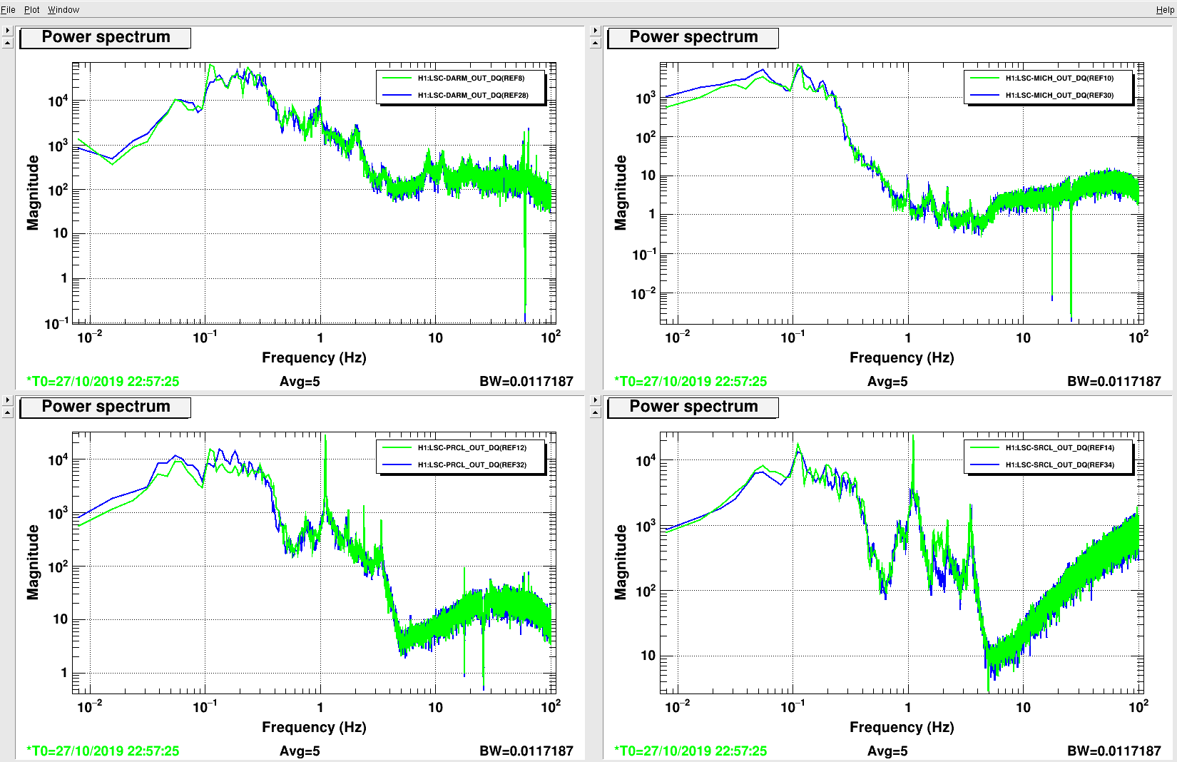
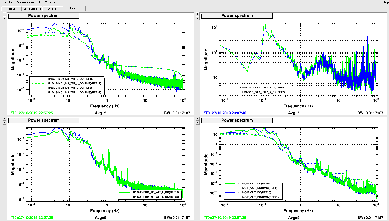
Today we tried new measurements for the ISI CPS DIFF in a configuration where both HAM2 and HAM3 in X direction and HAM4 and HAM5 in Y directions were ON. Also ITMY_Y and ITMX_X were locked together for the MICH configuration. BS was not locked to HAMs. We looked at PRCL, SRCL, MICH and also DARM in ALS configuration.
Results are shown in attachments: green traces represents the actuation system ON, while the OFF system configuration is in blue traces. Ground motion today was not bad because it was not windy, so less actuation was needed. PRCL, SRCL, MICH and DARM don't show a great improvement but it's important to notice that, as a first test on DARM and SRCL with both HAM and BSC chambers locked, it doesn't show any worse condition with respect to the system OFF.
We left the system ON.
We are also going on in building the guardian, which can be found under the name of ISI_DIFF. All modifications have been svn committed. We added two different DOWN states, one to swich *everything* OFF and one to switch only the LSC signals OFF, keeping CPS ON. We also made sure that the common limiters can switch ON after checking that everything else has been safely set OFF previously.
Today we changed the frequency of the AOM in the fiber distribution chassis to 160 MHz by sending an 80 MHz RF signal from the CER to the doubler. With the change of the PSL pick-off, the TTFFS beat note is now 160 MHz sharp, when locked. It won't change with the PSL/IMC AOM frequency anymore.
We updated the VCO nominal frequency, set the VCO frequency servo to internal and disabled the VCO feed forward.
[Jenne, Chiara, Varun]
L. Sun
The hourly C01 uncertainty budget plots and txt files (0611-1001) are stored here: https://ldas-jobs.ligo.caltech.edu/~ling.sun/Calibration/Uncertainty/O3C01_190611-191001/LHO/
(Note: the dir for batch 1 is kept as O3C01)
Since LHO has an IFO change on 0828 (SRC offset), the results are shown in separate chunks.
The scripts live in:
/home/ling.sun/Calibration/offlineJobs/run_C01_LHO_chunk2.py
/home/ling.sun/Calibration/offlineJobs/run_C01_LHO_chunk3.py
The submission files are:
/home/ling.sun/Calibration/offlineJobs/sub_C01_LHO_chunk2.sub
/home/ling.sun/Calibration/offlineJobs/sub_C01_LHO_chunk3.sub
------------------
LHO Chunk 2
------------------
1244307456 == Jun 11 2019 16:57:18 UTC
to
1251071403 == Aug 28 2019 23:49:45 UTC
(num of jobs: 1879)
------------------
LHO Chunk 3
------------------
1251071403 == Aug 28 2019 23:49:45 UTC
to
1253982208 == Oct 01 2019 16:23:10 UTC
(num of jobs: 809)
Results cover ~77% of the total number of hours. The current results are based on an overall PCAL uncertainty of 0.79%. The percentile and max bound plots are attached. They are generated using the following commands:
python RRNomStat.py --statDir=/home/ling.sun/public_html/Calibration/Uncertainty/O3C01_190611-191001/LHO/ --IFO=LHO --nameTag=O3_C01_190611-190828 --gpsStart=1244307450 --gpsEnd=1251071403
python RRNomStat.py --statDir=/home/ling.sun/public_html/Calibration/Uncertainty/O3C01_190611-191001/LHO/ --IFO=LHO --nameTag=O3_C01_190828-191001 --gpsStart=1251071402
The attachment demonstrates that the variation of the envelopes is negligible.
- White dashed curve: median of the median values from all the hourly data
- White solid curve: median of the +/- 1 sigma values from all the hourly data
- Color: percentiles of the +/- 1 sigma curves (i.e., variation of the envelope)
The PCAL corrections for O3a chunk 2+3 (alog LHO 52837) are applied in RRNom.py. The scripts and commands above remain the same.
The hourly uncertainty results are updated in the same dir. The new percentile plots are attached.
I've noticed that the Corner Station instrument air pressure has shown "RED" LOW on the MEDM screens periodically today. There had been an adjustment (reduction of the lead pressure switch cut-out) made a few days ago but this should have only effected the max pressure value and not the low value. Regardless, anything > 50 psi should prevent the pneumatic gate valve gates (GV5,6,7 and 8) from sagging into the beam path. I will investigate Monday -> or sooner if this becomes a problem today.
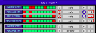
The h1susex models stopped running at 13:45 UTC (06:45 PDT) this morning (Sunday 27 Oct). This is a repeat of the last week's problem, in which h1susex appears to have lost an 18bit DAC (1-7 in that case, which was replaced with a spare).
I've stored all the system and Dolphin logs.
Looking at the PCI bus scan, there is a strange double entry for the 1-7 slot. Perhaps a board fault on this slot since this there is a new 18bit DAC card located there now?
Remember that even after replacing the suspect 18bit DAC, we got an 18bitDAC error on the first time the IOP model was started. I tested the DAC which was removed from h1susex on the DTS and it was not seen on the bus, suggesting it really was damaged.
Here is the alog from Wednesday afternoon when we replace the 1-7 18bitDAC on h1susex alog52664
FRS13748 had been opened Wednesday to cover the h1susex 18bitDAC issue, I'm adding today's details to it.
Richard and I have discuss this problem on the phone, we are going to avoid using slot 1-7 and we hope the DAC card currently in that slot is still good, if not we will use a second spare. I'm planning how to reshuffled the cards to avoid this slot with the minimum disruption in the ribbon cabling.
Richard is on site. We have a card shuffle plan, h1susex is powered down, Richard is making the change to the chassis initially relocating the current 18bitDAC card which was in slot 1-7.
Referencing the IO Chassis layout shown above (it is slightly out-of-date, there is a second ADC in slot 1-8 and the 18bit DAC in slot 2-5 is now a 20bit DAC)
We are:
This leaves the suspect slot 1-7 empty, using 1-2 instead. DACs in 2-x slots are unaffected.
Bad news, the 18bit DAC which was in slot 1-7, now relocated to 1-2 is not seen on the bus, presumably it has been damaged (will test on DTS tomorrow). Richard is now installing a spare 18bit DAC into slot 1-2.
suggests slot 1-7 damages cards installed in it.
Spare 18bit DAC in slot 1-2 is seen, we have a full compliment of cards.
As a sanity check that we have the correct DACs wired, I'm going to run the Duotone DAC-ADC loopback.
BTW, h1iopsusex came back with a negative IRIG-B error, should clear in a few minutes.
h1susauxex had a timing glitch while we were working on h1susex's IO Chassis. I restarted the models and it is good now.
IRIG-B timing is good again. I did a quick DAC duotone loopback test (last channel of first DAC outputs the duotone signal, which instead of going out to the field is looped back to the second to last channel of the first ADC). Timing value on IOP-TP MEDM showed a steady measurement of 70uS, which went back to a noise signal when I turned the DT test off.
Richard is damping SUS-EX and recovering SEI-EX from its watchdog trips.
Thank you Dave and Richard!
I have logged the latest h1susex dmesg. The IOP model is not reporting any issues, the AUTOCAL of the 18bit DACs and the 20bit DAC looks good.
It certainly looks like h1susex IO Chassis slot 1-7 is broken to the point that it damages cards. This will ultimately be resolved when we upgrade h1susex to the new IO Chassis, which presumably we could think about doing early if we have further problems with this IO Chassis (given the ease of running MTP fiber at the end station).