filiberto.clara@LIGO.ORG - posted 16:13, Monday 14 October 2019 (52462)
Bypass for HAM6 High Voltage Interlock removed
Jonathan, Erik, Dave:
WP8354
This morning we replaced the EY Dolphin IXS600 switch (with bad ports) with a new unit. We then saw h1cdsrfm problems, it could not activate its EY IXH611 card. After various reboots/restarts (which I'll detail later) we put the original switch back in.
At this time all the hardware is identical to early this morning, but h1cdsrfm still has issues with its EY IXH611 card.

At around 10:30am local, Betsy and I went to the CER mezzanine to turn on the high voltage for the TCS PZTs. X turned on without issue, but when I flipped the switch for the Y supply the light would flicker and there was a buzzing/humming coming from the unit. The voltage and amps read out as the same as on the X supply, but I didn't feel comfortable leaving it. I powered the unit down and came back with Fil who found the fan motor not turning. He will work on a replacement, until then the TCSY laser will be lasing but not stable.
Filed FRS13716
I ran a bruco for Sept 30th, one of the last locks in O3a after the 48 Hz peak was fixed (52184). Results are here
There is not much other than some lines at low frequency, and the usual SRCL/MICH/
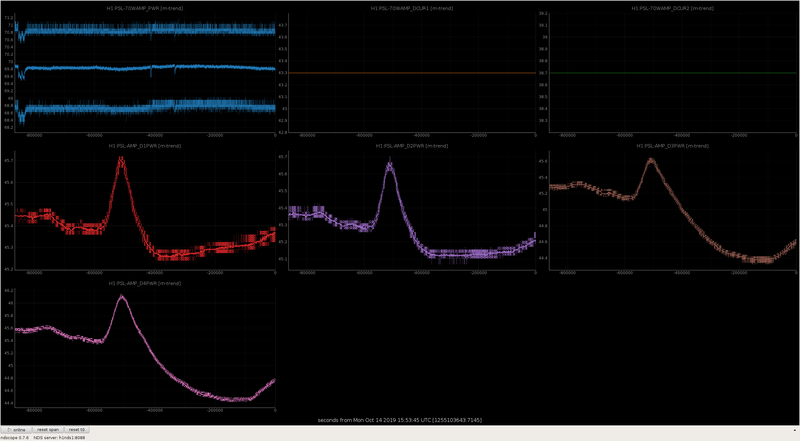
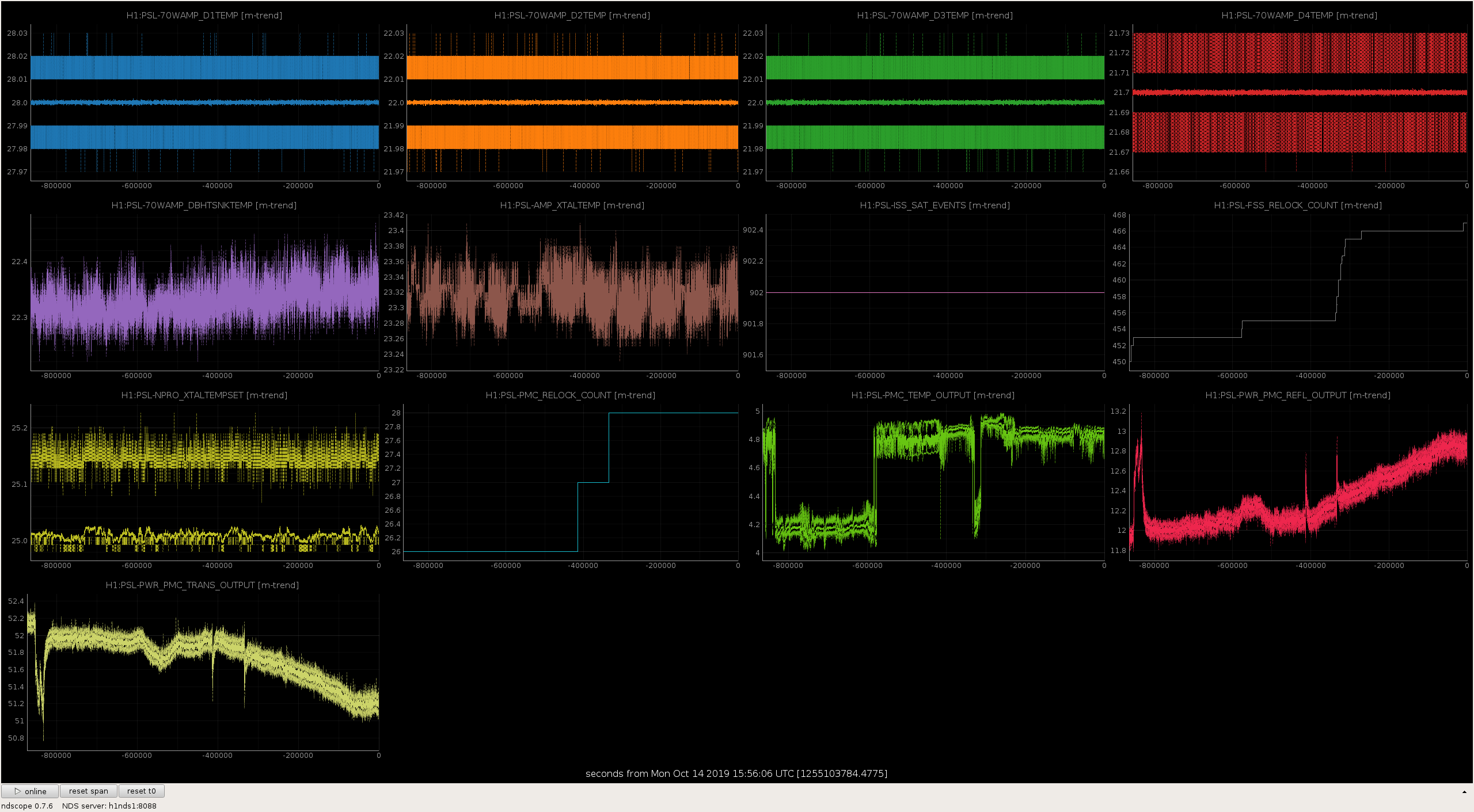
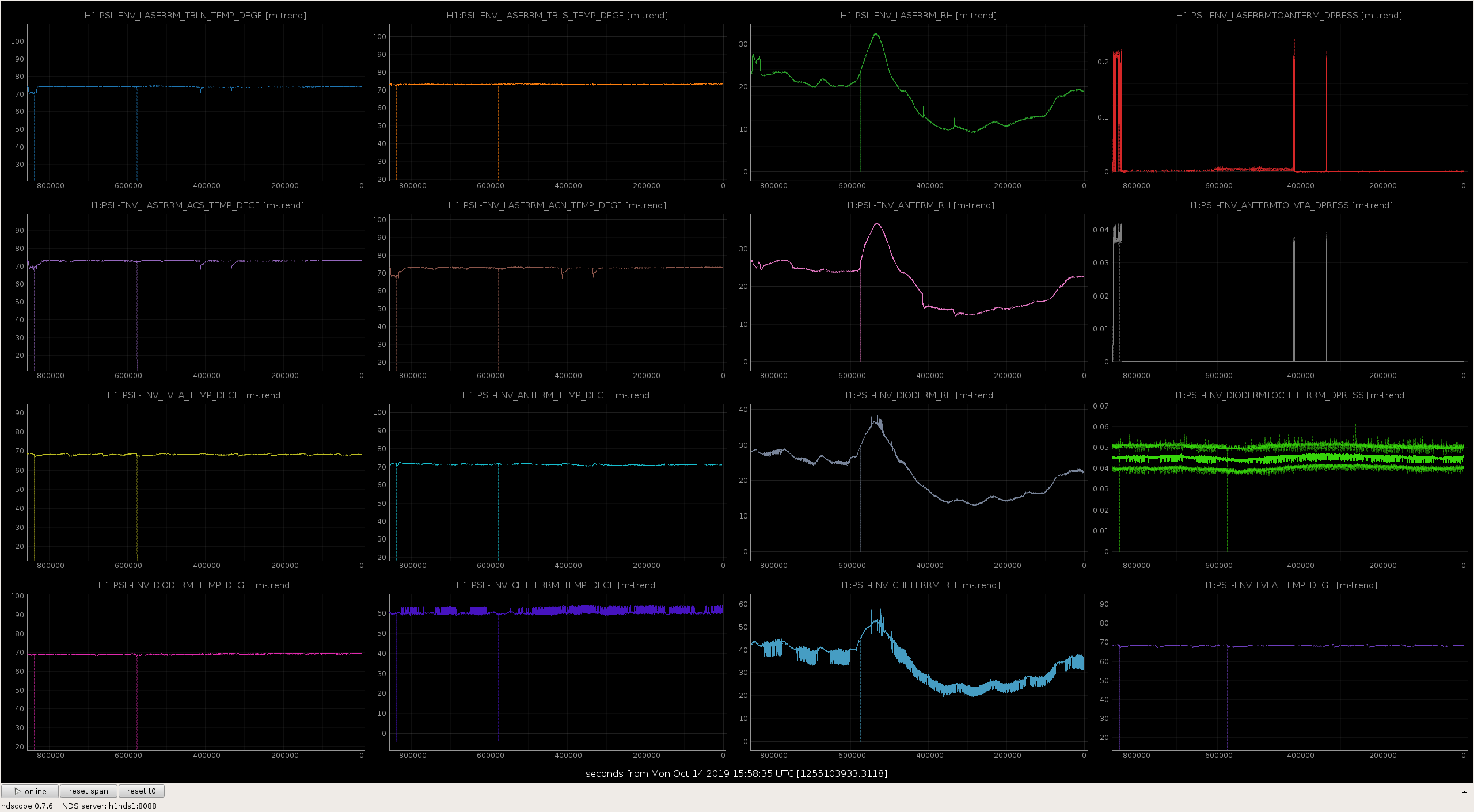

Addressed TCS Chillers (15:44-15:50utc)
While on ISCT1 I bumped the beamsplitter that is dumping power on the POP path before it gets to the POP AIR and POPX. It turns out all the screws were loose.
As the diodes are on transmission it doesn't look like it got too misaligned. I just torqued the screws where it currently is but have not realigned onto any of the diodes yet as my CDS laptop keeps crashing.
Cao and I are on site to work on installing the phase camera on ISCT1, part of work permit 8389.
We'll be in and out off the OSB optics lab and in the LVEA around ISCT1. As we'll be needing the POP beam on the table we'll also need PRMI locked.
Cao and I are done for today
We are back in, we'll be around ISCT1 and the electronics room.
Forgot to post when we left.
This weekend we managed to get the majority of the phase camera setup installed onto ISCT1. We are aiming to image each sideband at the POP port to help diagnose what might be happening to all our RF sidebands at LHO.
The phase camera needs a reference light field to image each sideband. The phase camera we are installing is detailed in P1900013, we are compiling a technical note on the setup which I'll post when it's more complete. The reference field comes from a fiber from the ALS distribution box (sample port ~2.5mW) which couples light onto an optical breadboard next to ISCT1. This has two free space AOMs on it which are double passed and allow us to shift the reference field in frequency relative to the carrier. The shifted light is fiber coupled from the breadboard on to ISCT1 where we have aligned and mode-matched it to the beam at POP. Some of the combined light is sent to a photodiode and used to phase lock the beat with the electronics driving the phase camera. So far the phase locking is working and the phase camera is demodulating the beam. However, some of our electronics died just before the weekend and we weren't able to fix it, so we didn't manage to get an actual image yet. We've come up with a solution that we'll try tomorrow and hopefully start gettings images of the beams in PRMI/DRMI.
(Chub, Jordan, Gerardo)
Re-installed IP10 on top of the new VAT valve. The joint was torqued down metal to metal, the joint still needs to be leak tested.
(Kyle, Gerardo)
Connected an aux cart to IP10 to pump it down to rough vacuum. Once at rough vacuum IP10 was isolated via it's two metal valves, we will continue with IP10 pump down on Monday.
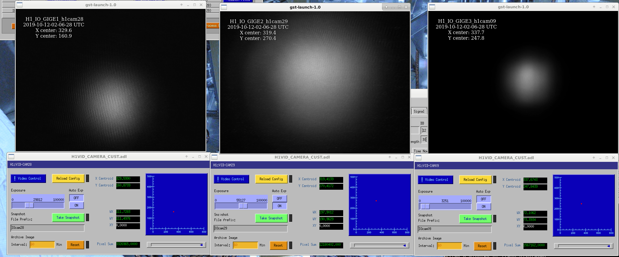
Not sure how some were changed, but found analog and digital gains changed, such that the camera on PMC trans was not reading a beam, and the straight through camera on the bottom periscope mirror was not reading a beam. Analgo gains are restored to 1 on all 3 cameras (text file, reload config), IOGigE1 (cam28), IOGigE2 (cam29), IOGigE3 (cam09). Digital gains set as in the attached snapshot.
Jeff, Sheila, Dan
We got the ok from Chandra to switch on high voltage equipment. We only wanted to switch on the ring heaters though (which are only +-15V so we're not sure why they get switched off?). To switch them on, at the TCS racks (back left corner in the CER) we just flipped the rocker switches on the back of each unit, test masses are now warming up. While we were there we also swtiched the SR3 heater on.
Per LIGO-M1300464, the procedure is to disable ring heaters during pressure transitions because it is unclear how heated metal will react to pressure changes.
[Keita, Nutsinee, Sheila, Jenne]
We went in to HAM6 today, and believe that we have finished all ISC/SQZ related tasks, and are ready to begin closeout procedures tomorrow. (Betsy, who has the final say, will write an alog or talk to the relevant folks for the actual final start of closeout.)
After Richard opened the PSL shutter and Ed locked the IMC, we pretty easily were able to get beam onto AS_C. To check our alignment, Sheila aligned the Michelson, then made sure we were still centered on AS_C. Since we don't have arms, we just assumed that the input beam is pretty close to its usual, and only adjusted ITMs and BS for MICH. Around this time, Keita noticed that there was a bit of a 'tail' on the beam as seen on an IR card. Sheila walked SR2 and SR3 until the tail was gone, but we were still centered on AS_C. After this we aligned SRY (restored SRM, misaligned ITMX) to get good fringes, so that we could trust the SRM position for squeezer-related work. We also took the IMC offline (which misaligns MC2) to remove the main IFO beam, injected the SQZ beam, ran the squeezer's ASC loops, and noted that the ZM1 actuators were very close to the edge of their ranges (as Sheila made a quick note about in alog 52405). We deferred action on this until after the main IFO path checks were complete.
Once we were happy with all of our alignments we brought the main IFO beam back and Nutsinee took photos of the beam in several different places, including the septum window, the position on OM1, the position relative to the fast shutter's wire, the position on OM2, the position going into and returning from the OMC shroud, and some photos to ensure that we don't see any obvious scattered light at the shroud apertures.
Having completed this, and deciding that it was still quite early in the day, we began work on relieving the ZM1 actuator. Sheila noted that the pico that is on/near the OFI is closer in Gouy phase to ZM2 than ZM1, so would not be a satisfactory way of relieving ZM1. Sheila and Keita went in and adjusted the last steering mirror on the VOPO platform that sends the beam to ZM1 about 1/4 of a turn in yaw, clockwise if you are standing at the endcap. After I damped the VOPO we re-ran the squeezer alignment loops, and found that instead of having outputs of nearly 29k the ZM1 outputs were at most about 7k. Excellent! We note that the ZM2 outputs are around 22k, but this is the same that they were during O3a, it hasn't drifted, and if we need to we can relieve ZM2 using the pico, so we are leaving things as-is.
With these 2 sets of checks and work, I believe that we are done with ISC/SQZ work in HAM6. Nutsinee will comment with her photos.
Nice work team!! We'll mobilize to do the chamber unlocking and closeout tomorrow!
Attached photos of beam at various places.
1) Beam coming out of septum window towards OM1 -- taken as close as possible to the beam height, vertical view
2) Beam coming out of septum window -- camera aligned to the beam as much as possible, horizontal view
3) Beam towards OM1 just before the fast shutter
4) Beam towards OM1 just after the fast shutter
5) Beam reflecting off OM1, in front of the fast shutter
6) Beam reflecting off OM1, behind the fast shutter
7) Beam next to the toaster again after a small alignment change. The beam location stayed pretty much the same.
8) Beam on OM1 (vertical view)
9) Beam on OM1 (horizontal view)
10) Beam on OM2 (vertical view)
11) Beam on OM2 (horizontal view)
12) Beam on OM2 (IR camera)
13) Beam going into OMC, reflects off OM3
14) Beam going into OMC, vertical view
15, 16, 17) OMC input output port area (IR camera looking for scattering)
18) Beam relative to the wire when fast shutter closed
19) OMC refl on beam dump
20) Beam reflects off fast shutter to beam dump
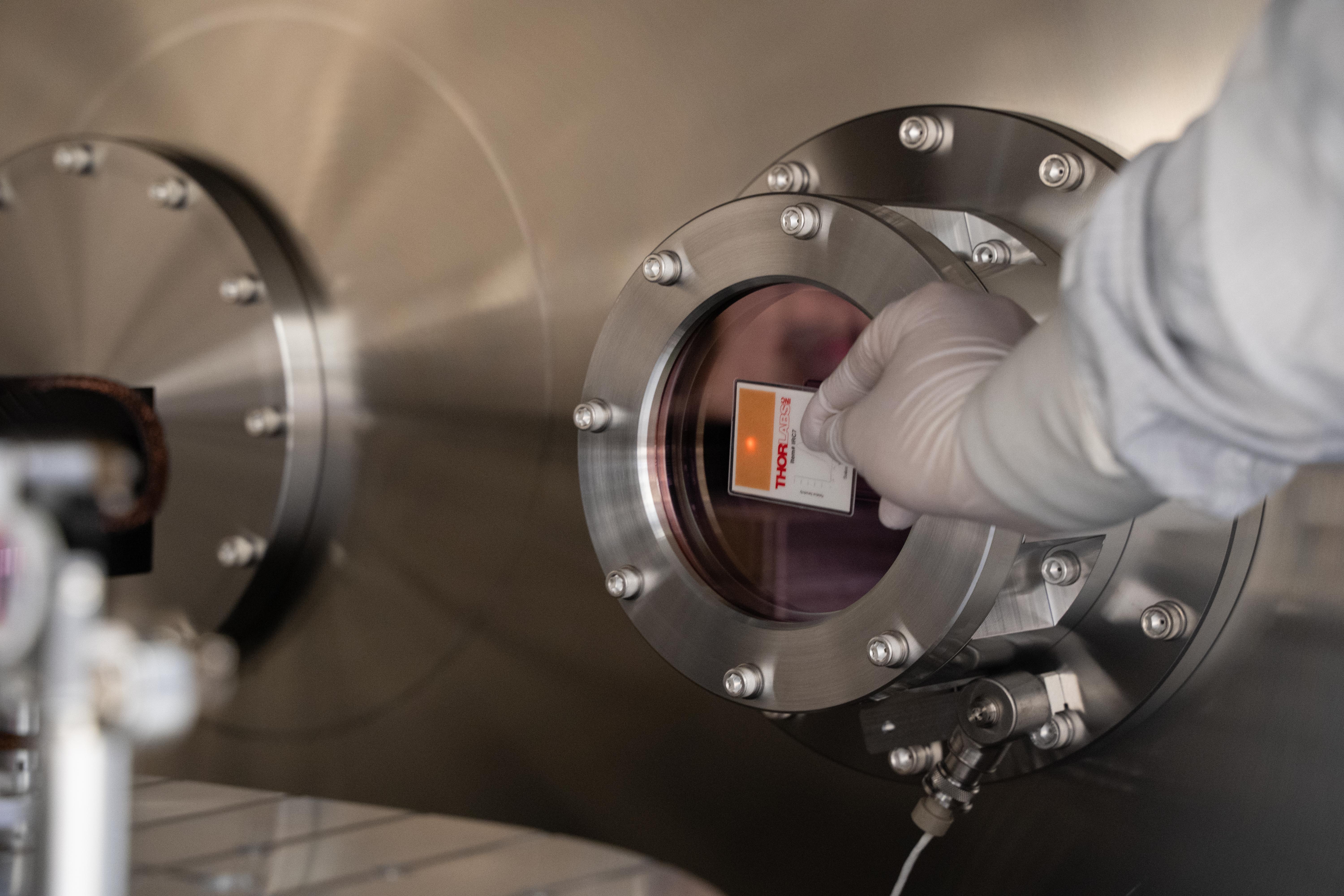
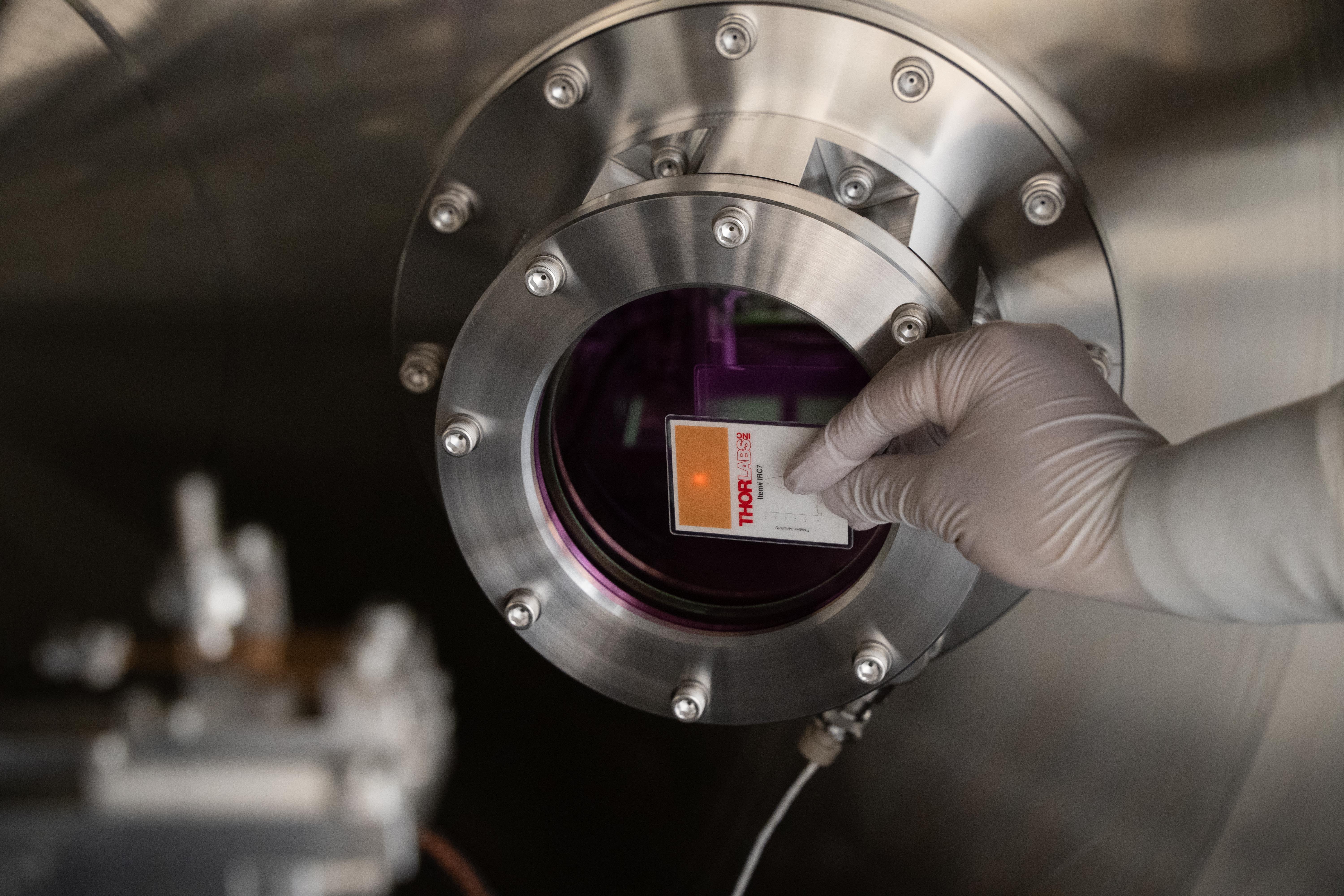
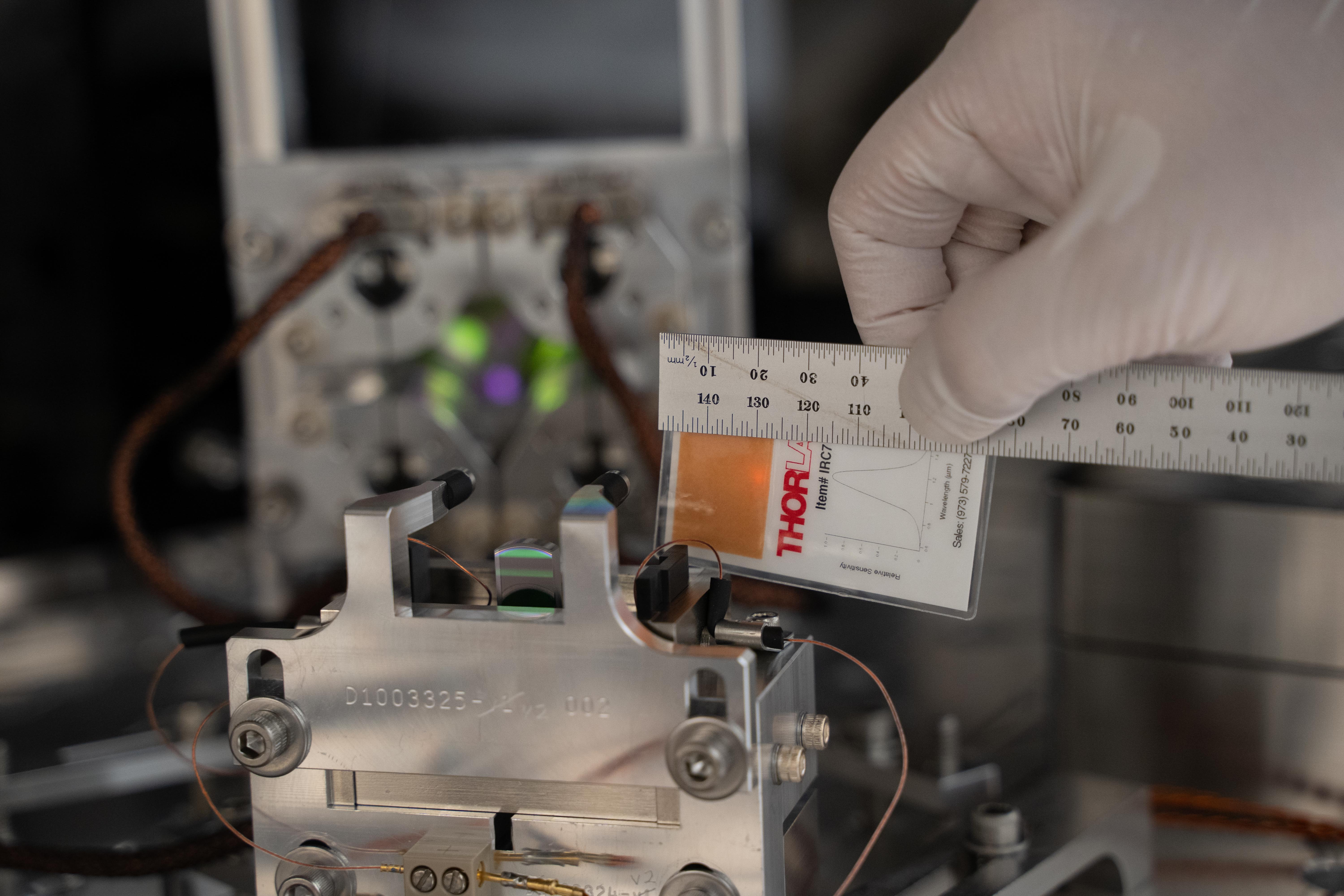
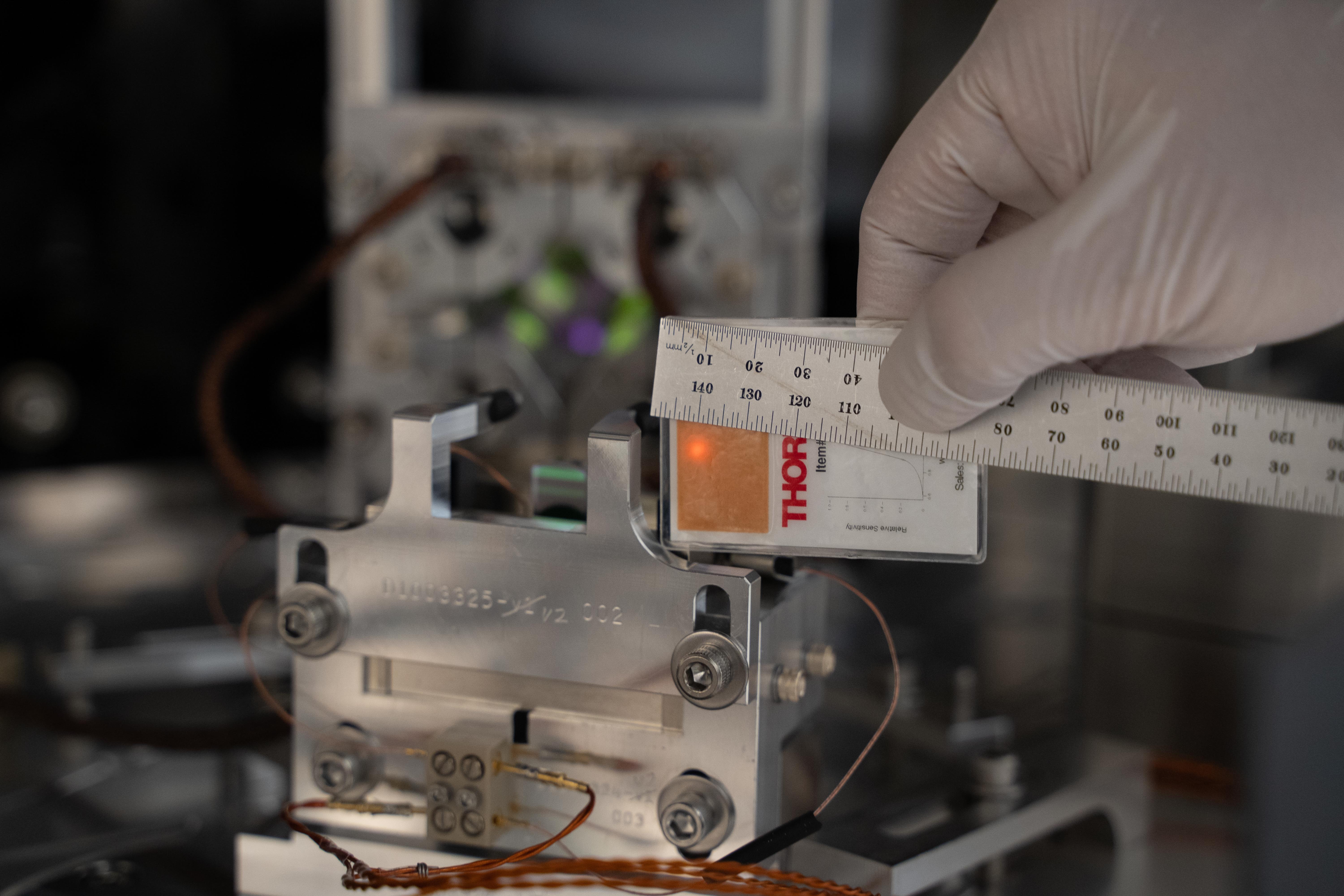
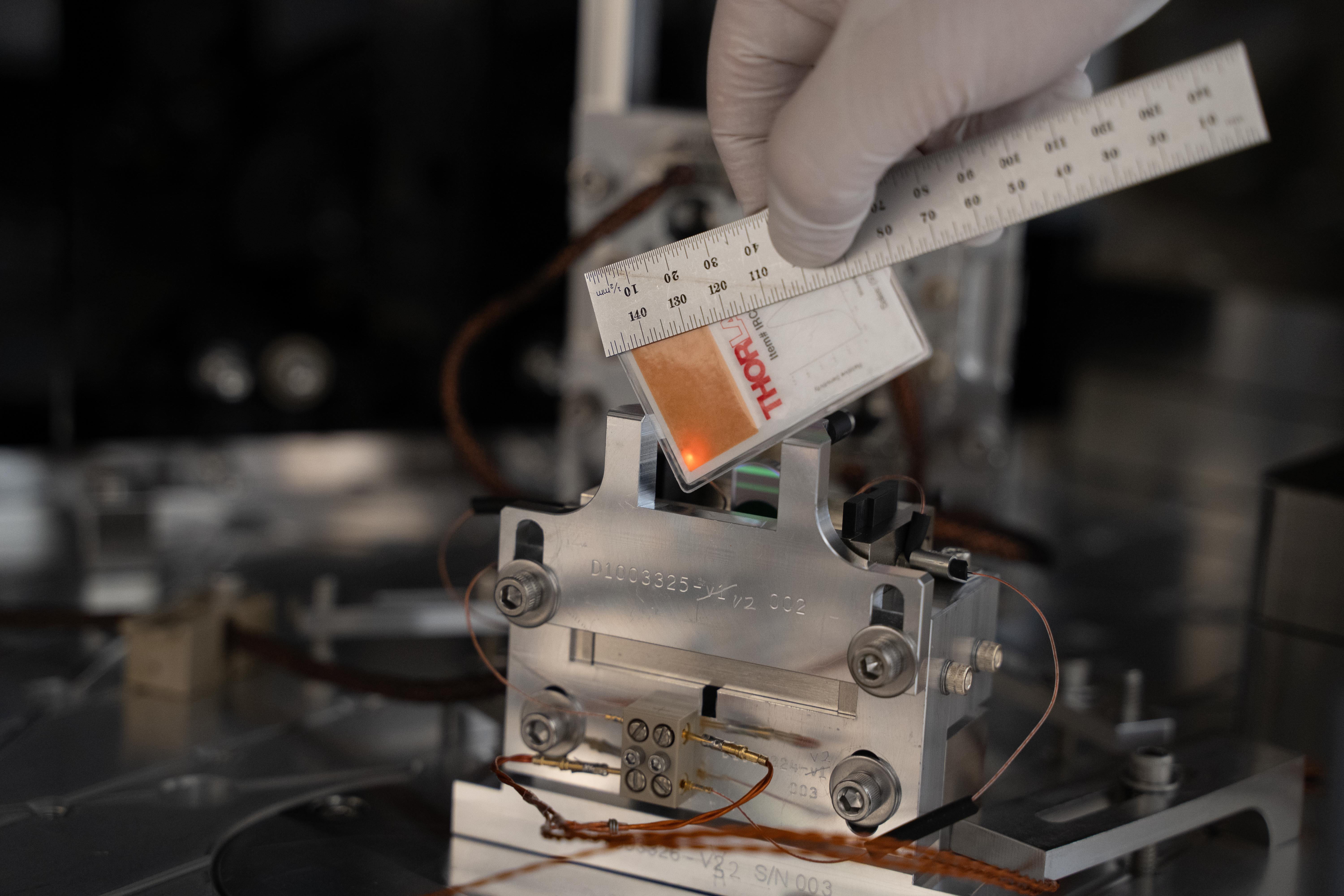
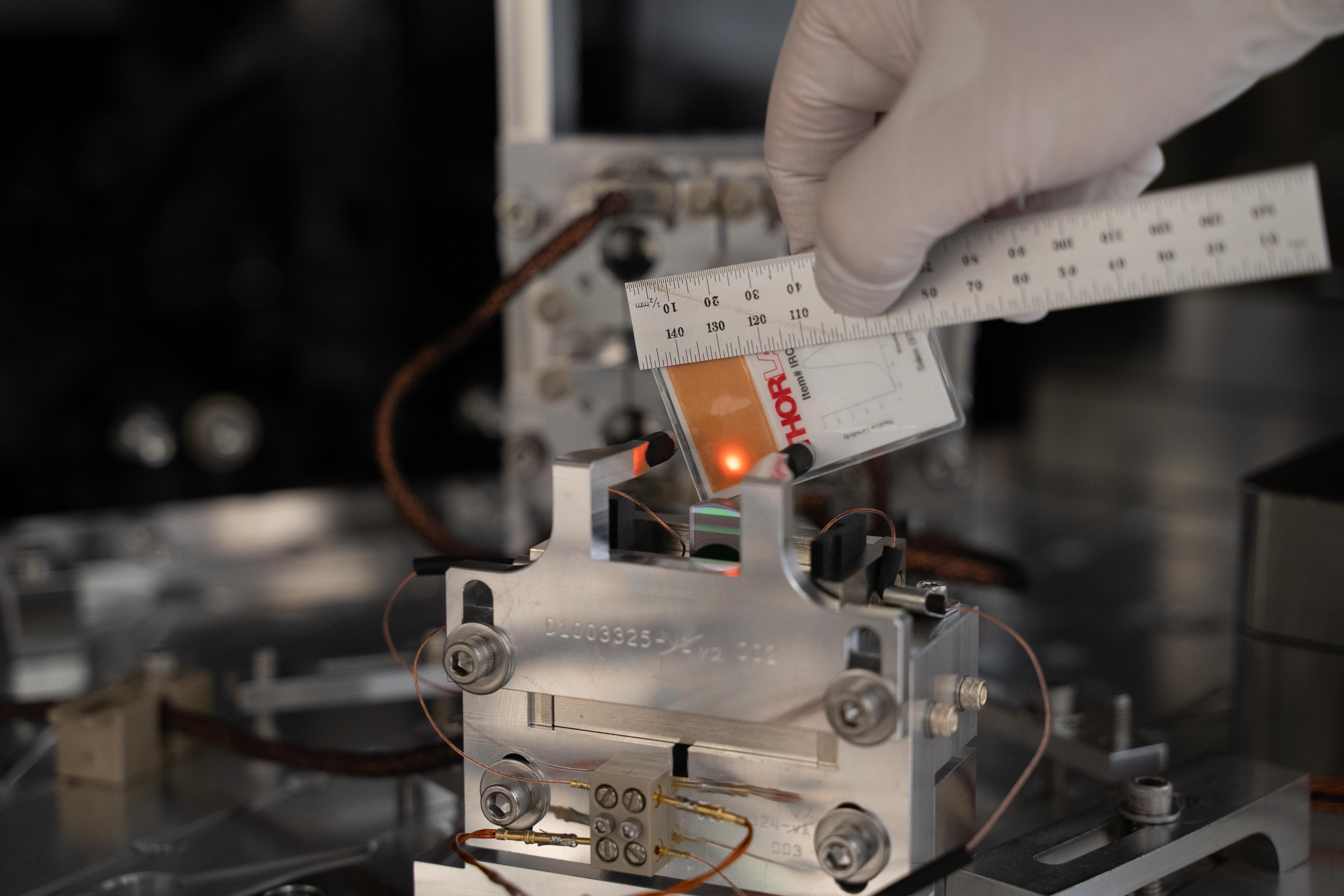
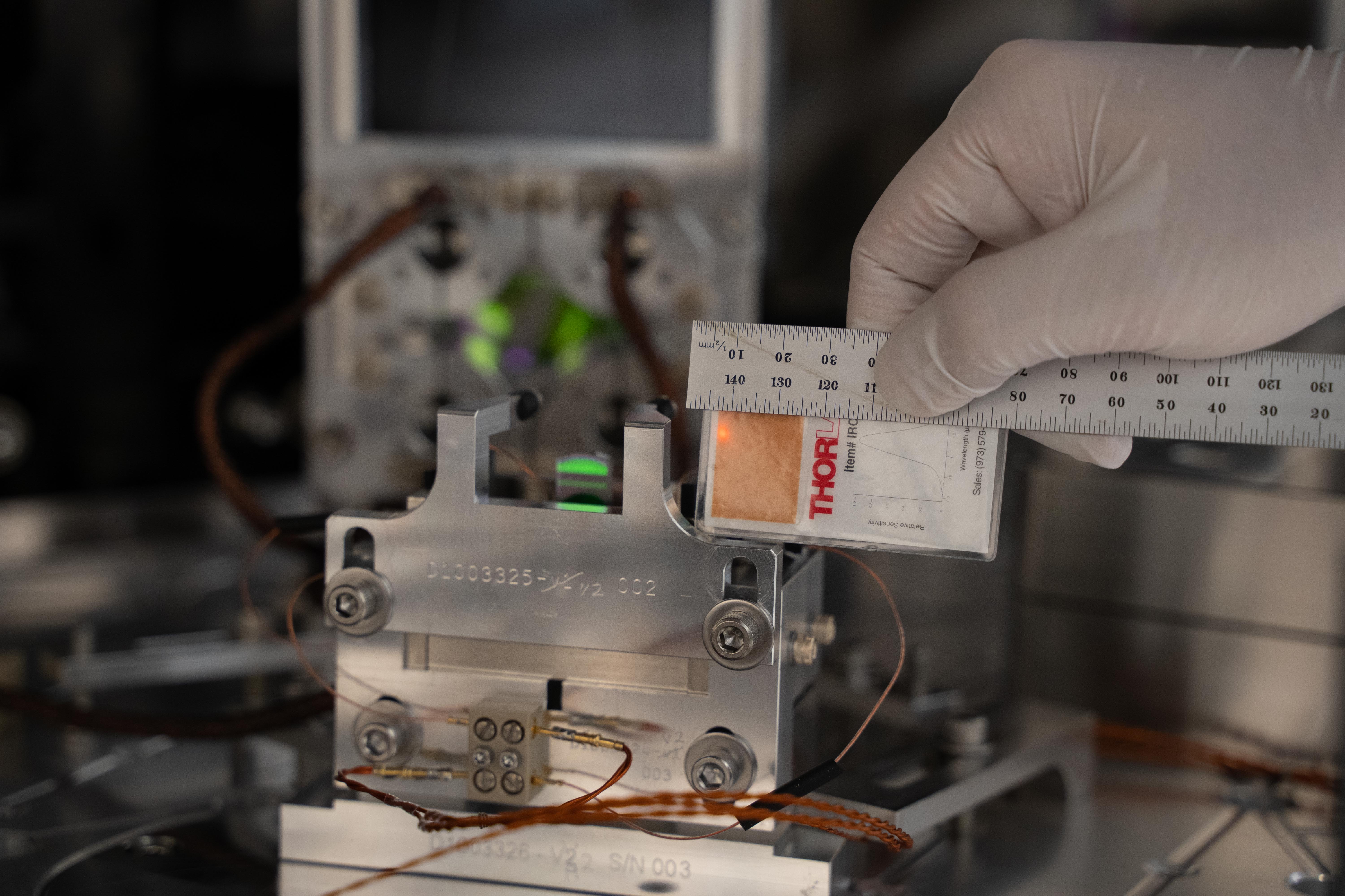


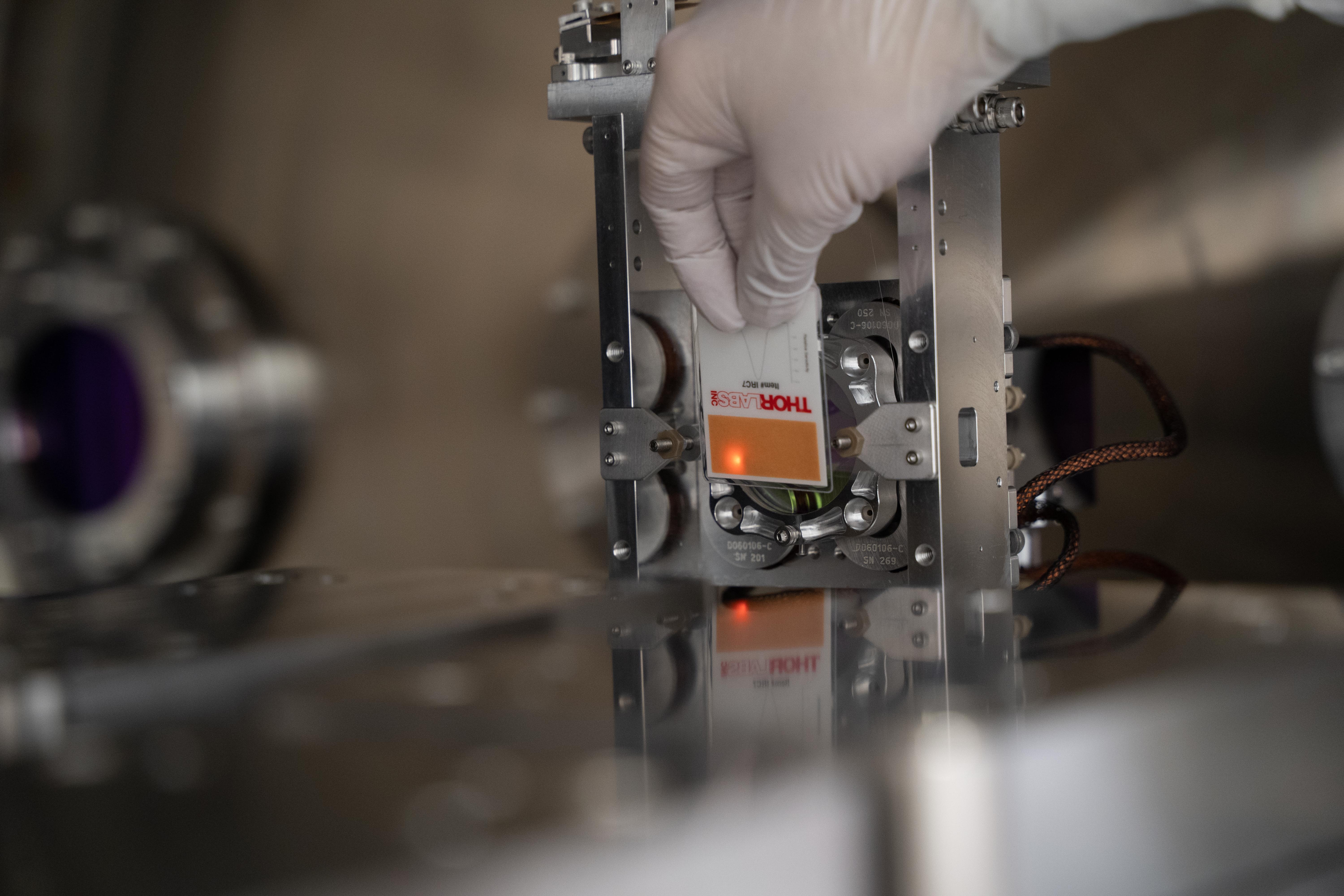
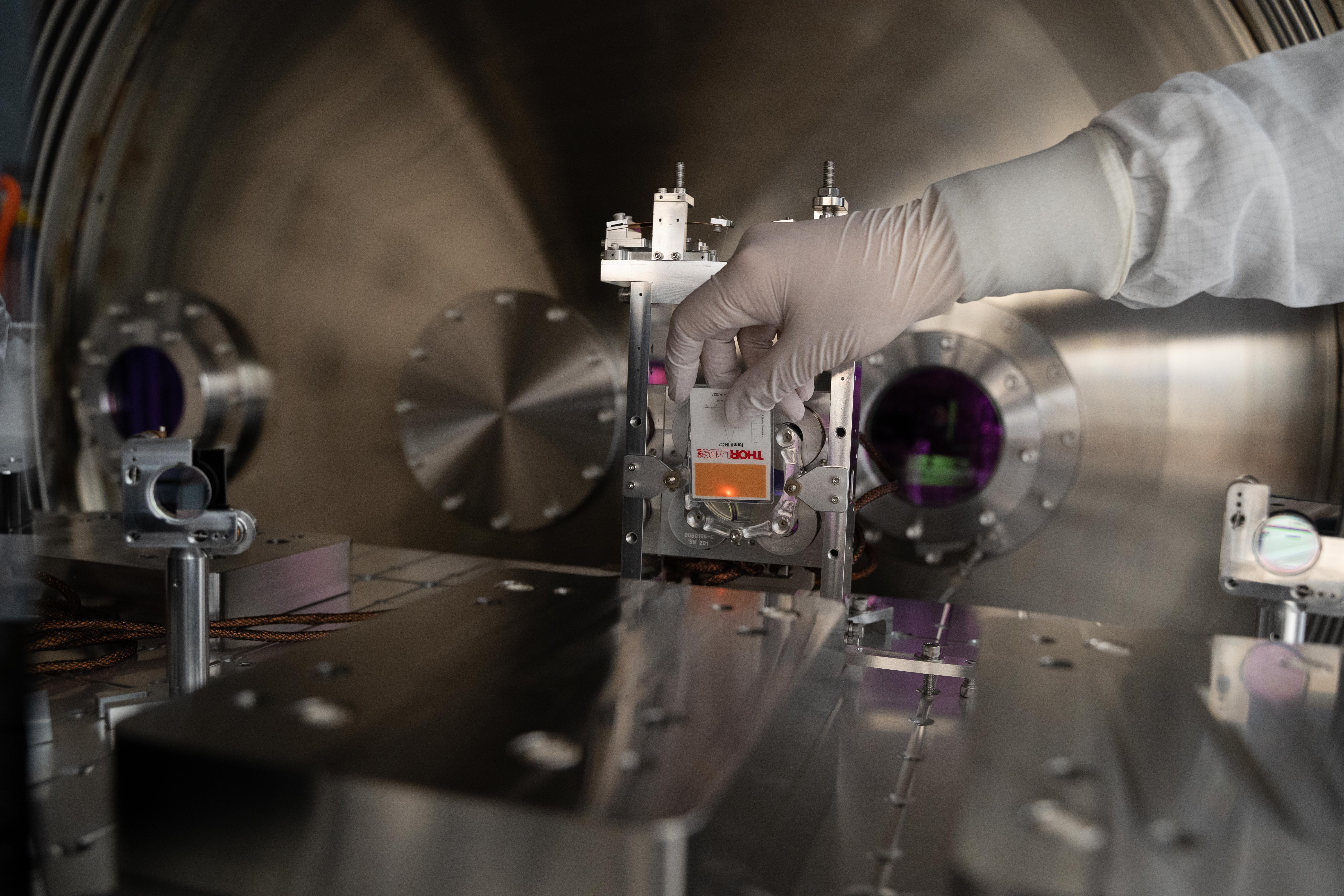
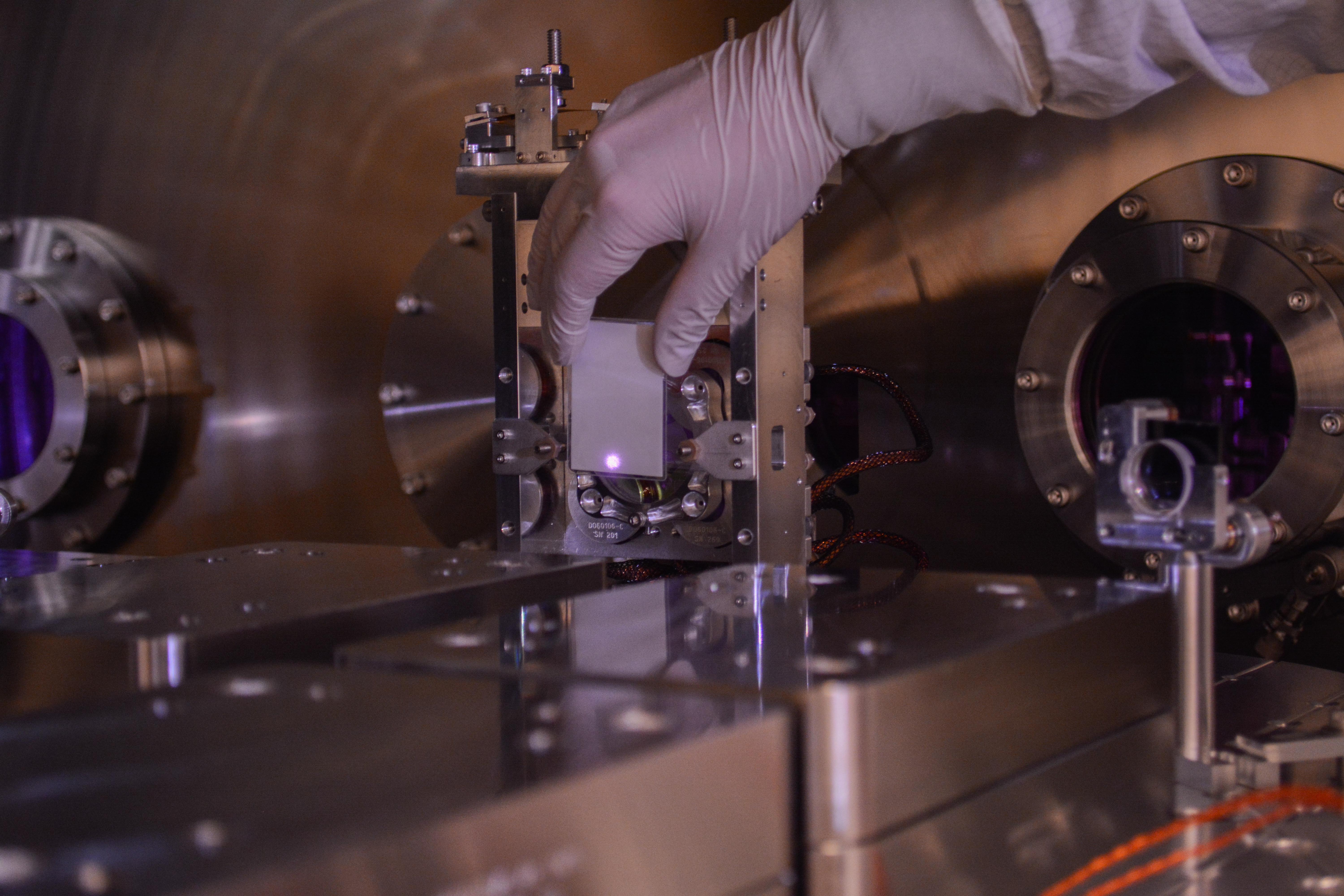
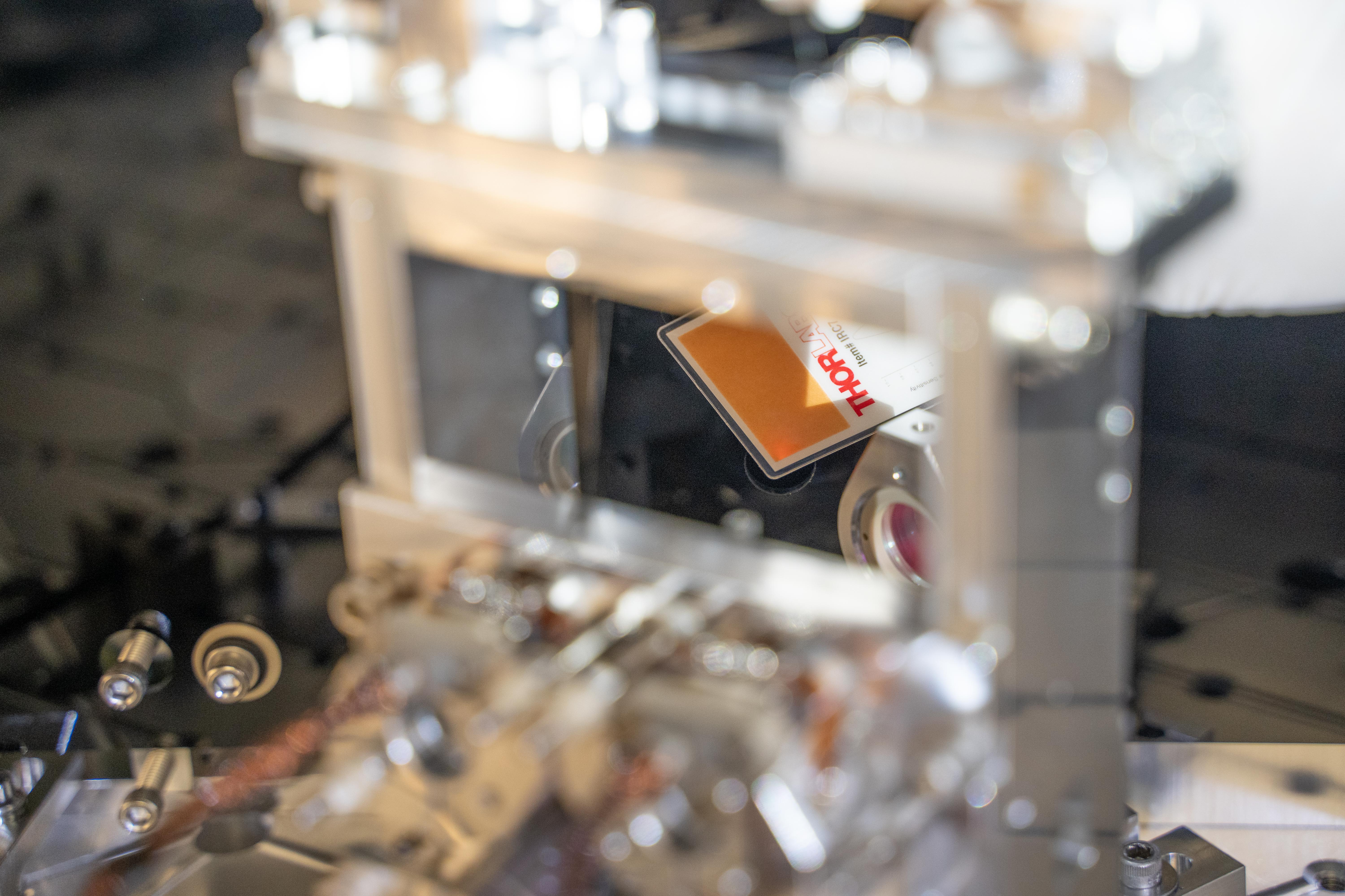
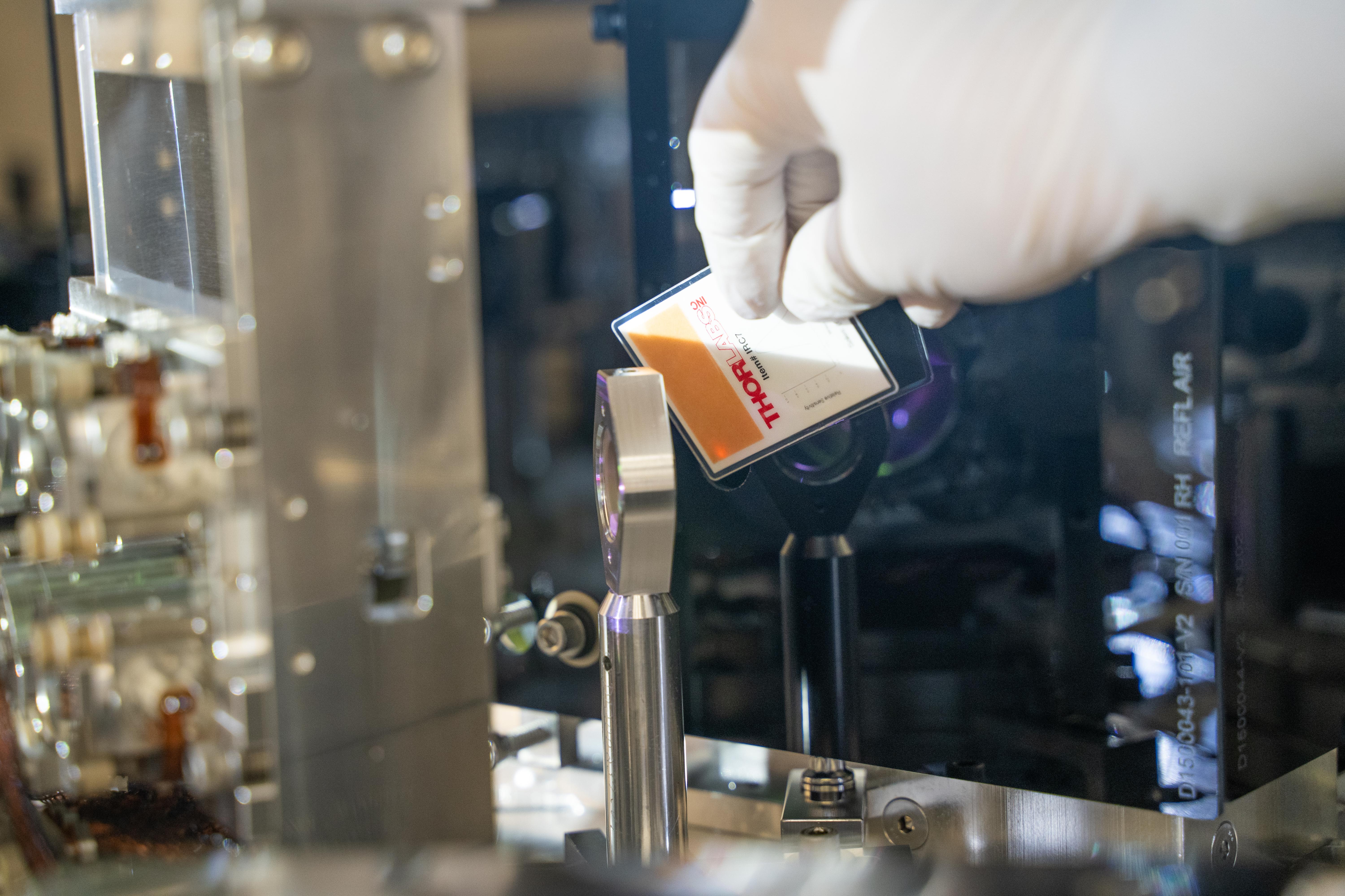
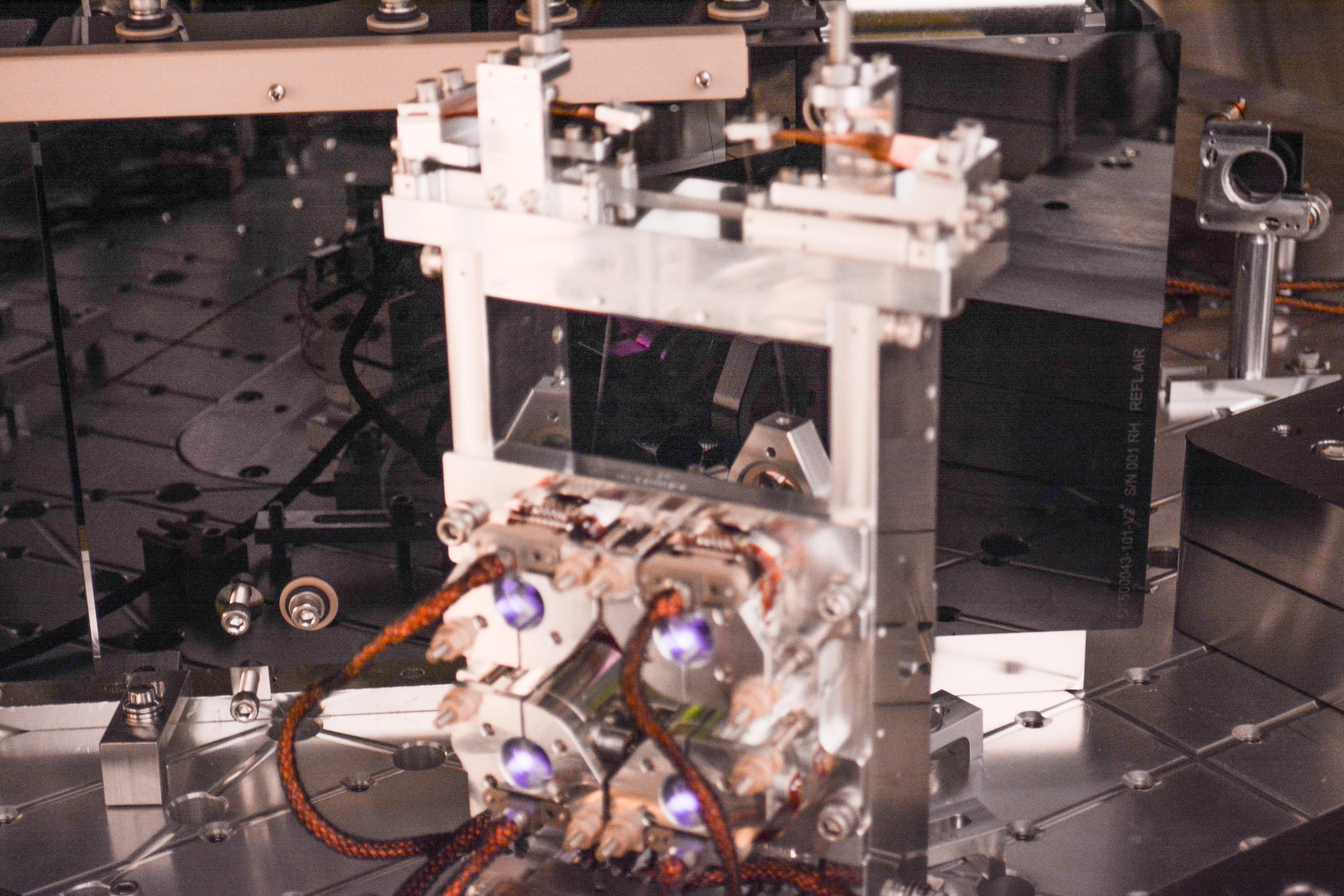
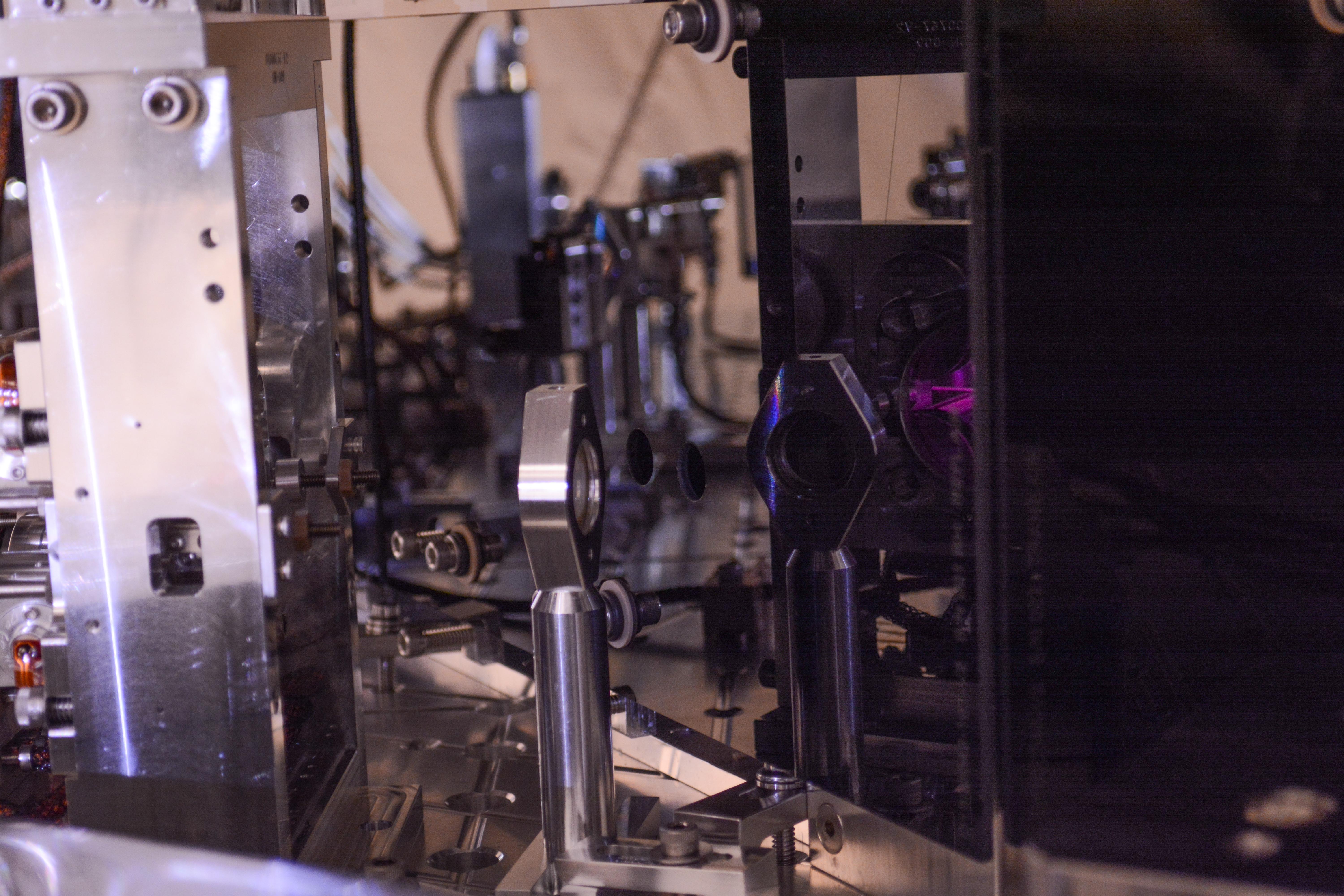
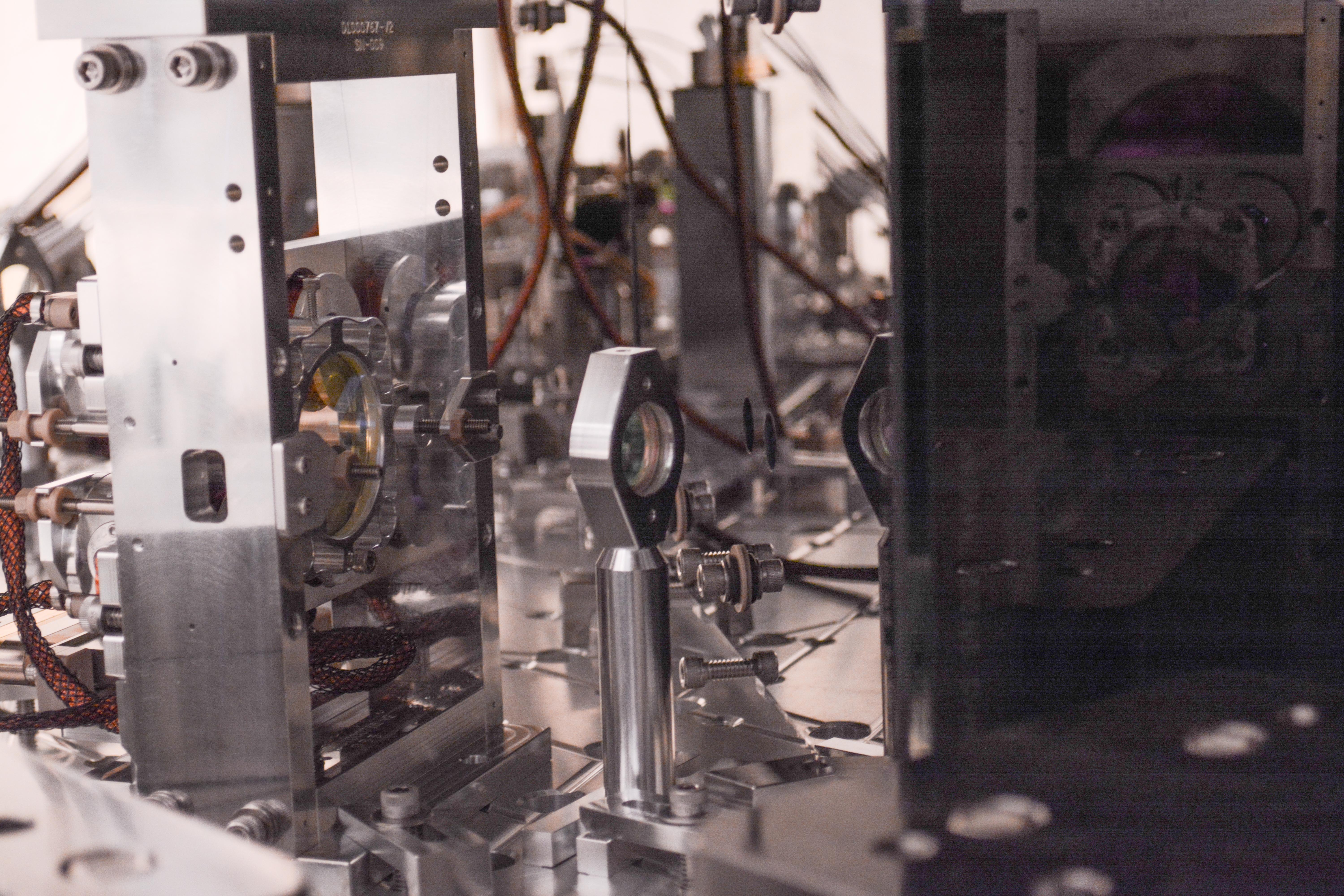
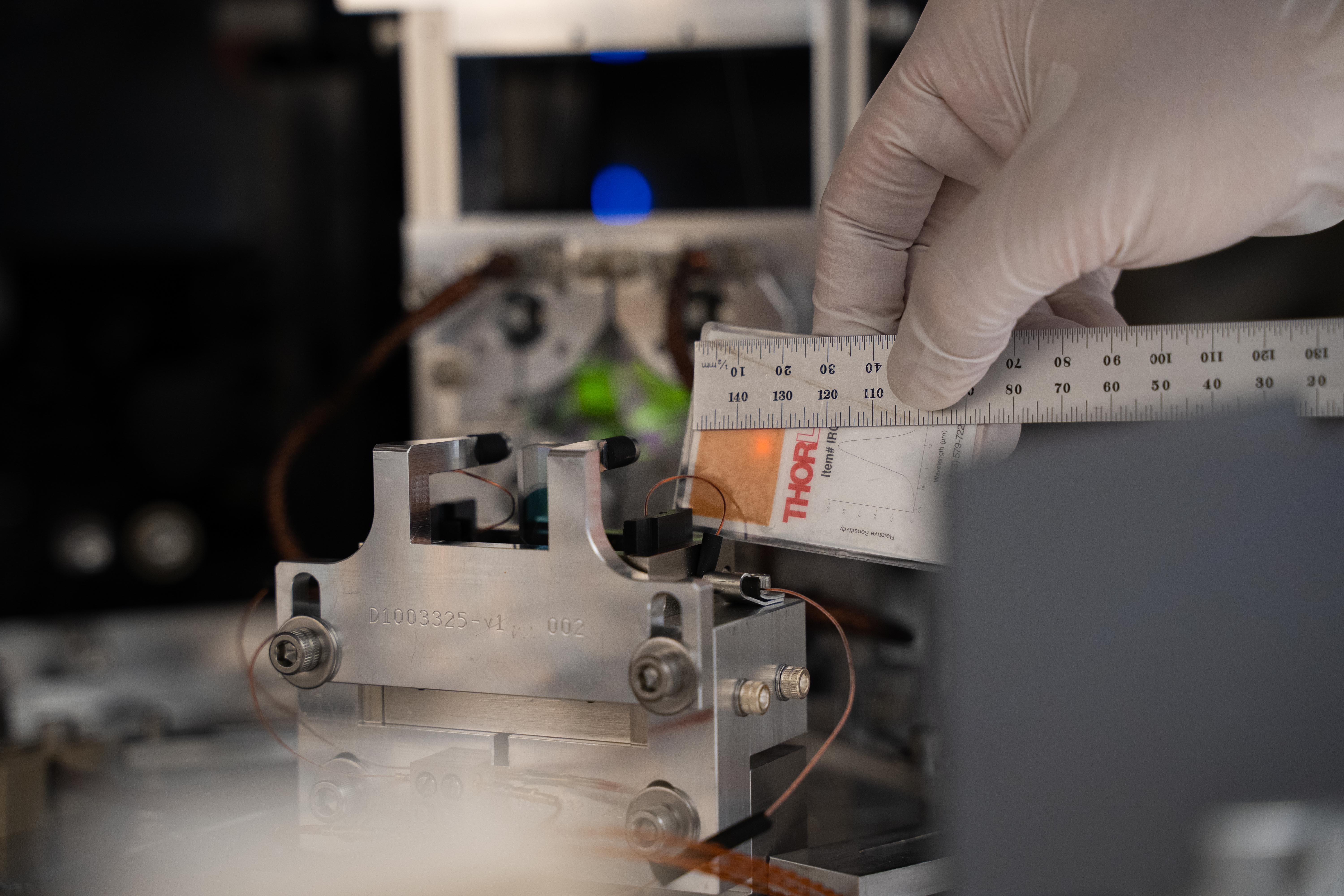


Before-swap pictures were posted in alog 52310.
Oct 11, 2019 Close-out sweep of HAM6 photos are here.
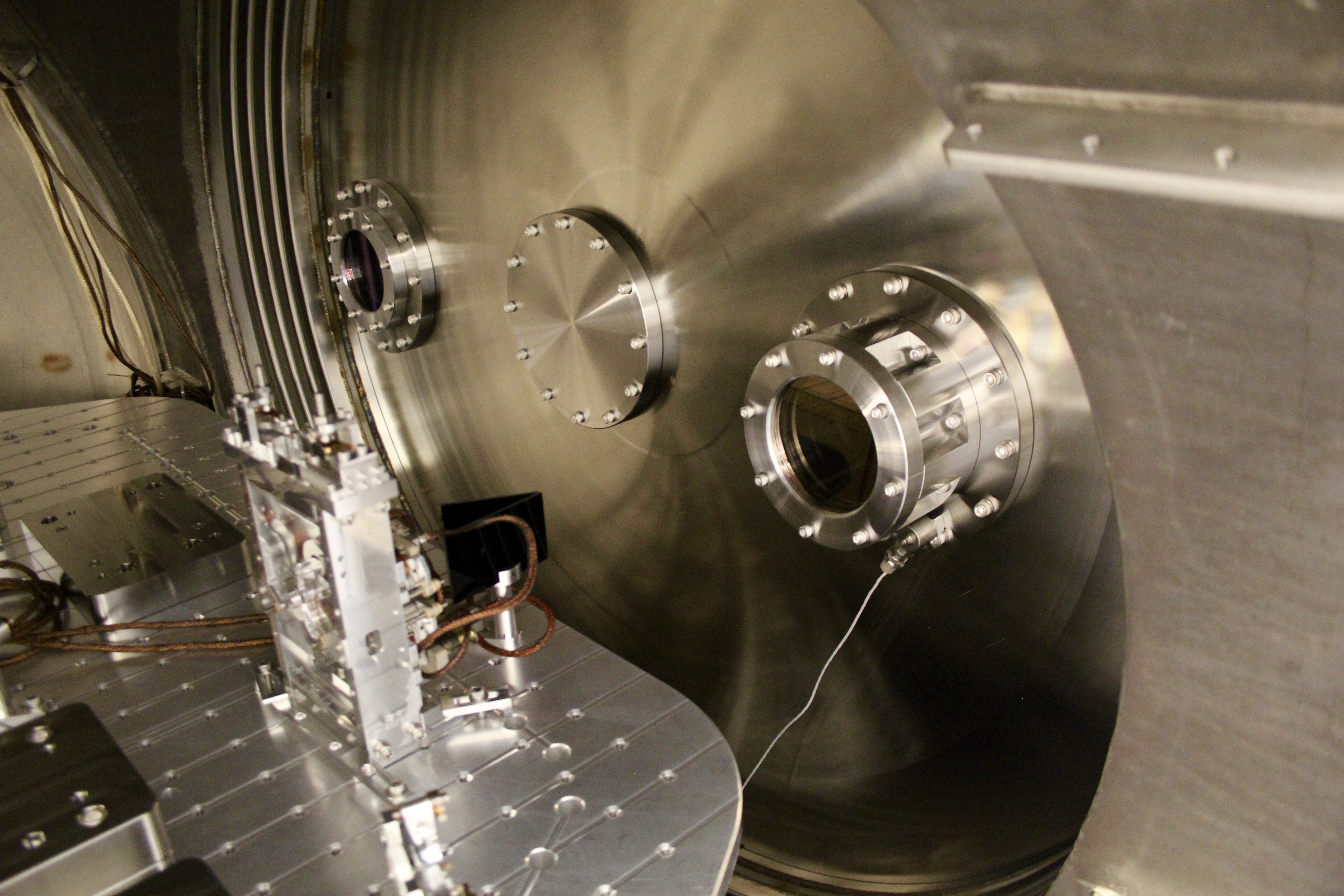
Since Resource Space appears to no longer be functionable/useable, here are some photos of the septum flanges/viewports.


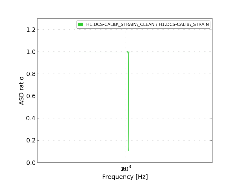
I've done some testing to see how well the line subtraction algorithm in the gstlal calibration pipeline works when used to remove the roaming calibration line (> 1kHz, and changes periodically). Since the line subtraction has already been reviewed, I mainly wanted to investigate what happens right around the time that the line frequency changes. The gstlal calibration pipeline reads in the line frequency from the raw frames, so it is able to change frequency. Fortunately, the line frequency only changes when we are not in low noise, so there should be no concern about noise being injected at the moment of the change. The attached plots show data from around a time when the frequency changed from 2501.3 Hz to 2001.3 Hz, at GPS 1239997514 (Mon Apr 22 19:44:56 UTC 2019).
The first four plots are ASDs and ASD ratios from just before the change. Note that the 2501.3 Hz line is not subtracted very effectively.
The next four plots are ASDs and ASD ratios from just after the change. After the change, the 2001.3 Hz line is subtracted effectively, as expected.
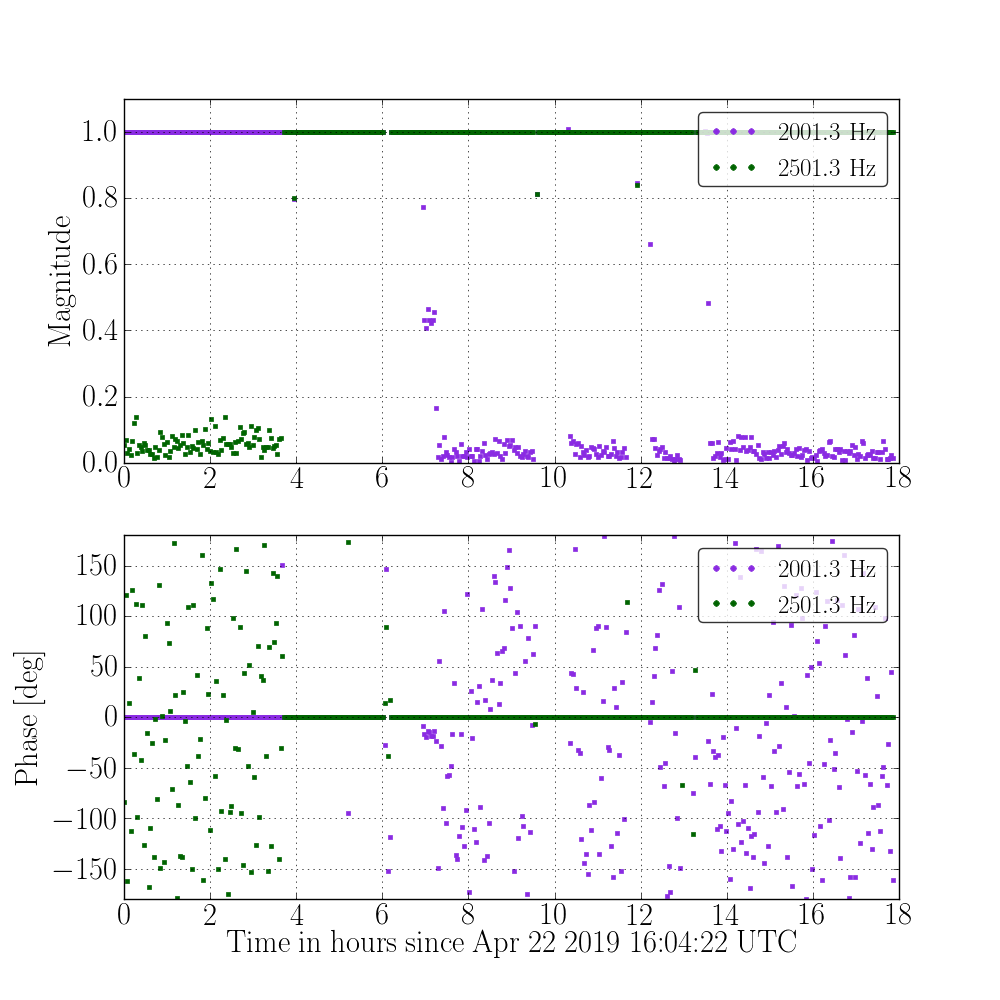
The next (9th) plot is a time series of ratios of (cleaned data) / (uncleaned data) at the roaming line frequency, showing magnitude and phase. Note that the line subtraction of the 2501.3 Hz line stops working before the time of the change. It appears as though the algorithm is switching the frequency before the frequency actually changes. I will need to investigate this more to find out why this is happening. Hopefully, it can be fixed by a configuration change.
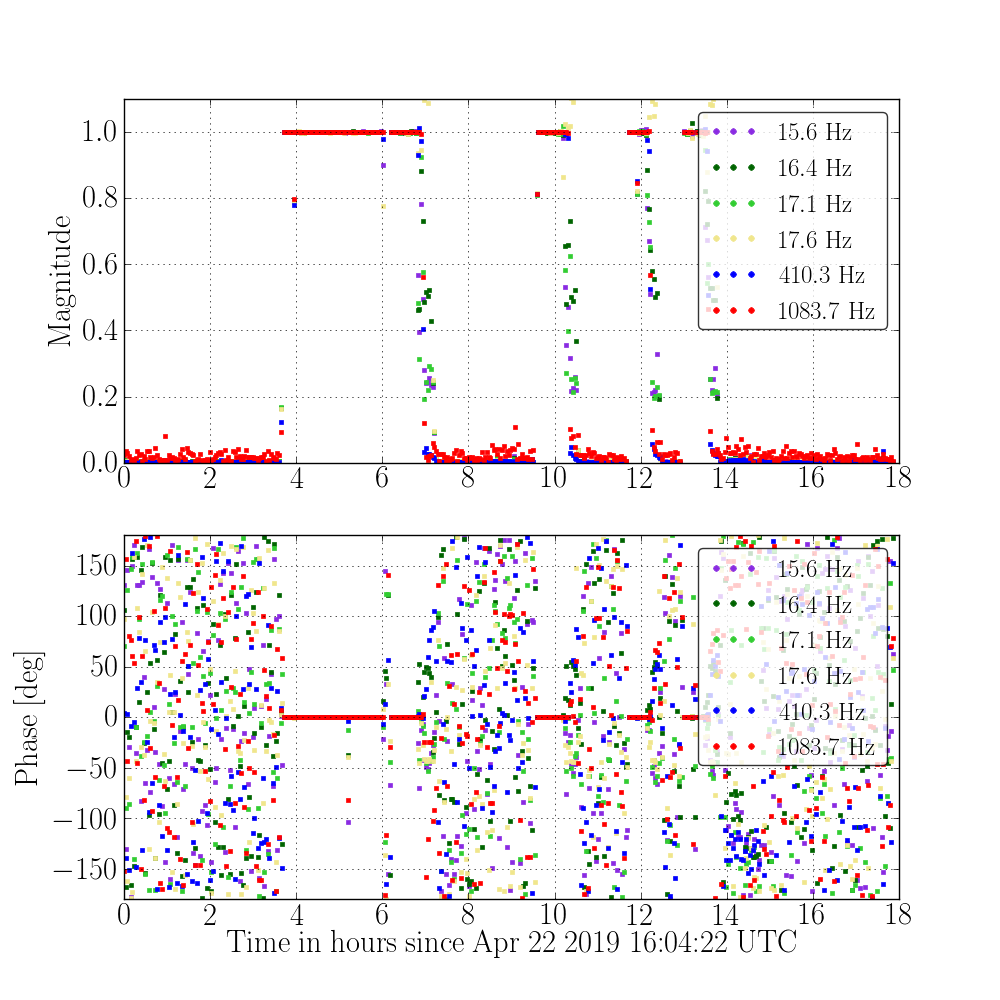
The last plot is similar to the previous one, except that it is for the regular calibration lines, so it provides a reference for roughly how effective the subtraction should be.
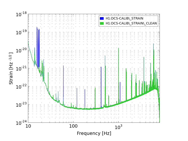
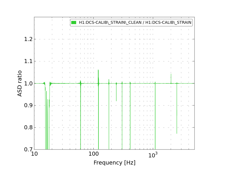


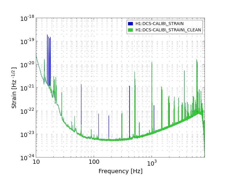
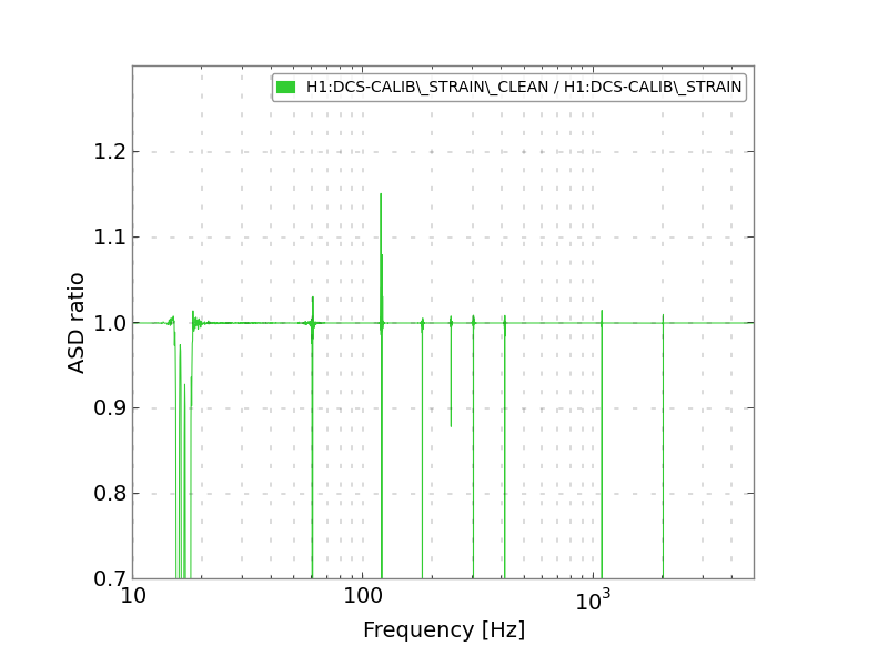
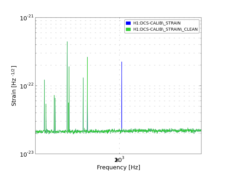
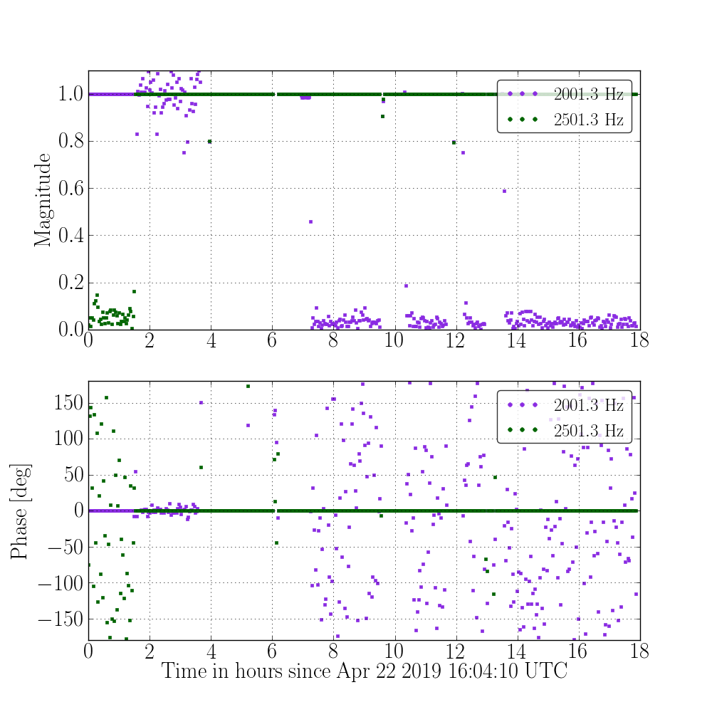
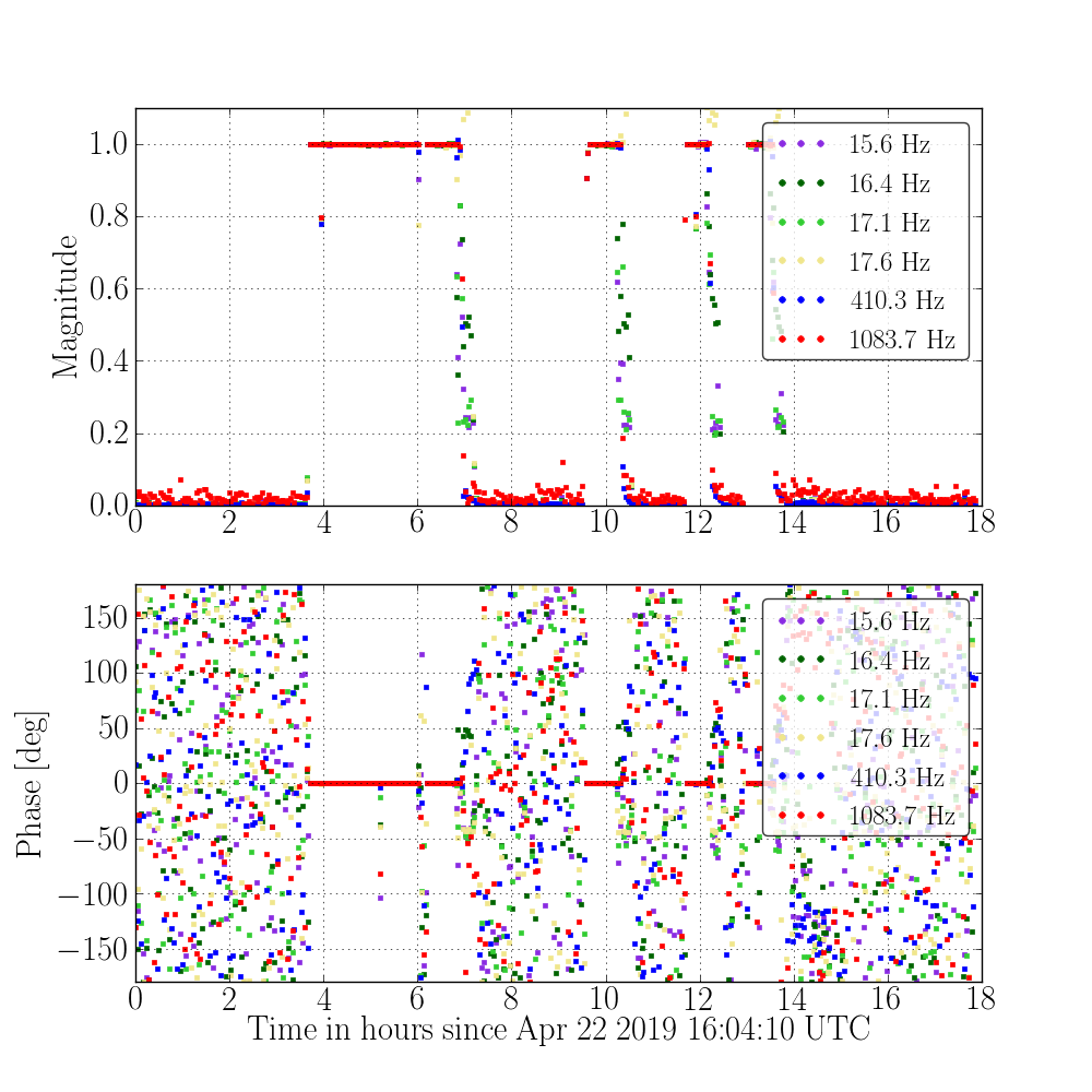
After some investigation, I found the problem causing the line frequency to be updated too early. When run offline (in DCS/C01 mode), the gstlal calibration pipeline has access to large amounts of data all at once, allowing computationally cheap processes to operate much faster than expensive ones. The reading in and updating of the calibration line frequencies is cheap, so it happens quickly, before the calibrated h(t) and subtraction algorithm are ready. The process of updating calibration lines involves changing a property of a gstreamer element, which is not necessarily timestamp-synced, unlike many other processes, such as adding two streams. The fix to the problem was to use the GstController, a tool which allows GObject properties to be updated over stream time. I've made this fix, it appears to have worked. The first attached plot is a time series of ratios of (cleaned data) / (uncleaned data) at the roaming line frequency, similar to the one in the above aLOG. The update occurs just before the 4-hour mark in the plot. The second plot is a similar plot showing all the other calibration lines, which do not change during this time.