Displaying reports 38261-38280 of 89075.Go to page Start 1910 1911 1912 1913 1914 1915 1916 1917 1918 End
Reports until 16:03, Tuesday 08 October 2019
H1 General
edmond.merilh@LIGO.ORG - posted 16:03, Tuesday 08 October 2019 (52347)
Shift Summary - Day

TITLE: 10/08 Day Shift: 15:00-23:00 UTC (08:00-16:00 PST), all times posted in UTC
STATE of H1: Planned Engineering
INCOMING OPERATOR: Cheryl
SHIFT SUMMARY:
LOG:

14:32 Jeff B out to ends  - DM checks & flow testing

15:12 Chandra and Tyler out to LVEA

15:25 Chub and Jordan out to LVEA

15:35 Gerardo out to LVEA -  N side of HAM 5

15:44 Chris using forklift by Rear high-bay to move spool pieces

15:45 Chandra just informed me that there is to be NO work in HAM6 at all today due to vac team "roughing" out the vertex.

15:5 untripped everything except for HAM6 because the ISI is locked

16:00 Paradise water delivery on site

16:07 Christina out to LVEA -checking on / assisting with cleaning

16:25 Placed all SUS in HAM6 to SAFE

16:29 Chris back and out to LVEA

16:33 Unifirst on site

16:40 Nutsinee out to LVEA- SQZT6

16:50 Jeff B back and out to LVEA fo DM - also DR and optics lab

17:00 Dan and Cao out to optics lab

17:10 Gerardo back - taking some gear to MX

17:23 Corey out to check on the TCS chillers

17:33 Hugh out to HAM7

17:34 Corey back

17:40 Jeff B back

18:00 Corey out to LVEA - HAM7

19:01 Christina forklifting a pallette over to the H2 building

19:08 Corey and Hugh back

20:52 Tyler back - heading to mid stations

21:07 Hugh and Gavin out to HAM7

21:18 Travis to MX

21:33 Richard to HAM6 to check on Filiberto

21:35 Tyler back from mid stations

21:52 Chandra leak checking Y beam manifold

21:57 Travis back from mid X


H1 ISC (DetChar)
keith.riles@LIGO.ORG - posted 13:57, Tuesday 08 October 2019 (52351)
More blinking LEDs?
Summary: There appear to be periodic transients in h(t) that are similar to (but nonetheless different from) those seen in the past from the infamous blinking LEDs in the timing electronics. From looking at magnetometer channels, I think the strongest (only?) coupling sources are near or in the EX_EBAY_SUSRACK and/or EY_EBAY_SUSRACK electronics.

More info:

It has taken a while, but the old Michigan data-folding infrastructure is working again (thanks to undergraduate Reilly Penhorwood).

Figure 1 shows the May-August H1 DELTAL_EXTERNAL folded upon itself in 8-second folds (observing mode only). The top plot is the raw average over those folds, the middle left plot is the full spectrum of the top fold, the middle right plot is the "band-passed" zoom of the left plot, and the bottom plot is the inverse Fourier transform of the band-passed FFT coefficients. One sees what appears to be a combination of 1-second and 2-second periodicity.

Figures 2-3 show the corresponding plots for the EX magnetometer channels (no restriction on observing mode) EX_MAG_EBAY_SUSRACK_Y_DQ and EX_MAG_EBAY_SUSRACK_Z_DQ (the corresponding plots for the X direction are not yet available).

Figures 4-6 show corresponding plots for the EY channels (x, y and z directions): EY_MAG_EBAY_SUSRACK_X_DQ, EY_MAG_EBAY_SUSRACK_Y_DQ and EY_MAG_EBAY_SUSRACK_Z_DQ

One sees in all of these figures evidence of transients close to integer seconds and about 0.15 second later, with in many cases (including in h(t)) a slight difference between even and odd integer seconds (but not nearly as pronounced as what we saw in O1 from the original blinking LEDs).

Reilly has a web page with many more plots for individual months/days and for other magnetometer channels (and for corresponding L1 channels) here. Other magnetometer channels also show disturbing transients, but not with the same time structure as seen in h(t). The direct links for drilling down to month/day for the six channels above are

H1:CAL-DELTAL_EXTERNAL_DQ
H1:PEM-EX_MAG_EBAY_SUSRACK_Y_DQ
H1:PEM-EX_MAG_EBAY_SUSRACK_Z_DQ
H1:PEM-EY_MAG_EBAY_SUSRACK_X_DQ
H1:PEM-EY_MAG_EBAY_SUSRACK_Y_DQ
H1:PEM-EY_MAG_EBAY_SUSRACK_Z_DQ

We are still working to include the April and September data, to produce different band passes to exclude the low-frequency calibration lines for cleaner plots and to produce completer magnetometer data for L1, but wanted to give a heads up early in the commissioning break that EX and EY electronics seem to have blinking devices.

Non-image files attached to this report
H1 SEI
edmond.merilh@LIGO.ORG - posted 12:08, Tuesday 08 October 2019 (52355)
SEI seismometer mass position check - Monthly FAMIS #9094

2019-10-08 11:30:55.356159
There are 1 STS proof masses out of range ( > 2.0 [V] )!
STS B DOF X/U = 4.704 [V]

All other proof masses are within range ( < 2.0 [V] ):
STS A DOF X/U = -0.86 [V]
STS A DOF Y/V = -0.944 [V]
STS A DOF Z/W = -0.38 [V]
STS B DOF Y/V = -0.426 [V]
STS B DOF Z/W = -0.434 [V]
STS C DOF X/U = 0.229 [V]
STS C DOF Y/V = 1.223 [V]
STS C DOF Z/W = -0.32 [V]
STS EX DOF X/U = -0.22 [V]
STS EX DOF Y/V = 0.277 [V]
STS EX DOF Z/W = 0.103 [V]
STS EY DOF X/U = 0.219 [V]
STS EY DOF Y/V = -0.189 [V]
STS EY DOF Z/W = 0.607 [V]

Assessment complete.

Averaging Mass Centering channels for 10 [sec] ...
2019-10-08 12:03:45.359422There are 18 T240 proof masses out of range ( > 0.3 [V] )!

ETMX T240 2 DOF X/U = -0.898 [V]
ETMX T240 2 DOF Y/V = -0.726 [V]
ETMX T240 2 DOF Z/W = -0.77 [V]
ITMX T240 1 DOF X/U = -1.423 [V]
ITMX T240 1 DOF Y/V = -0.325 [V]
ITMX T240 2 DOF X/U = -0.367 [V]
ITMX T240 2 DOF Z/W = -0.352 [V]
ITMX T240 3 DOF X/U = -1.373 [V]
ITMY T240 2 DOF Z/W = -0.301 [V]
ITMY T240 3 DOF X/U = -0.855 [V]
ITMY T240 3 DOF Z/W = -1.324 [V]
BS T240 1 DOF X/U = -0.369 [V]
BS T240 1 DOF Y/V = -0.553 [V]
BS T240 2 DOF X/U = -0.329 [V]
BS T240 2 DOF Z/W = -0.391 [V]
BS T240 3 DOF X/U = -0.412 [V]
BS T240 3 DOF Y/V = -0.431 [V]
BS T240 3 DOF Z/W = -0.756 [V]

All other proof masses are within range ( < 0.3 [V] ):
ETMX T240 1 DOF X/U = -0.137 [V]
ETMX T240 1 DOF Y/V = -0.146 [V]
ETMX T240 1 DOF Z/W = -0.253 [V]
ETMX T240 3 DOF X/U = -0.212 [V]
ETMX T240 3 DOF Y/V = -0.262 [V]
ETMX T240 3 DOF Z/W = -0.162 [V]
ETMY T240 1 DOF X/U = -0.193 [V]
ETMY T240 1 DOF Y/V = 0.03 [V]
ETMY T240 1 DOF Z/W = -0.148 [V]
ETMY T240 2 DOF X/U = -0.092 [V]
ETMY T240 2 DOF Y/V = -0.152 [V]
ETMY T240 2 DOF Z/W = -0.109 [V]
ETMY T240 3 DOF X/U = -0.172 [V]
ETMY T240 3 DOF Y/V = -0.207 [V]
ETMY T240 3 DOF Z/W = 0.027 [V]
ITMX T240 1 DOF Z/W = -0.21 [V]
ITMX T240 2 DOF Y/V = -0.252 [V]
ITMX T240 3 DOF Y/V = -0.294 [V]
ITMX T240 3 DOF Z/W = -0.291 [V]
ITMY T240 1 DOF X/U = -0.112 [V]
ITMY T240 1 DOF Y/V = -0.262 [V]
ITMY T240 1 DOF Z/W = -0.205 [V]
ITMY T240 2 DOF X/U = -0.053 [V]
ITMY T240 2 DOF Y/V = 0.012 [V]
ITMY T240 3 DOF Y/V = -0.079 [V]
BS T240 1 DOF Z/W = -0.191 [V]
BS T240 2 DOF Y/V = -0.101 [V]


Assessment complete.

H1 AOS
jeffrey.bartlett@LIGO.ORG - posted 12:00, Tuesday 08 October 2019 (52354)
Quarterly Dust Monitor Testing (FAMIS #12979)
  Ran zero count and flow rate tests on dust monitors EX Loc#1, EY Loc#1, CS Loc#6, Loc#10, Optics Lab Lab#1, Lab#2, Diode Room DR Loc#1. Will check the two monitors in the PSL enclosure next week, when in for cleaning. 

  All zero counts and flow rate tests passed, except as noted below. 
 
  Optics Lab Loc-#1- lowered the flow down to the 2.8L/M rate. 

  Diode Room DR Loc#1 - The flow is down to about 2.7L/M This is close to the 2.6L/M lower operating limit. This unit does not have adjustable flow rate. If the flow drops any lower will need to swap the unit out and send it back for service.   

   Closing FAMIS #12979

  
H1 CAL (CAL)
timesh.mistry@LIGO.ORG - posted 11:53, Tuesday 08 October 2019 (52346)
NCAL Update -- First Spin with Masses and End Station Fit Check

[Jeff Kissel, Rick Savage, Eddie Sanchez, Patrick Thomas, Timesh Mistry]

Update for 07th October 2019

EX NCAL Mount Fit Check

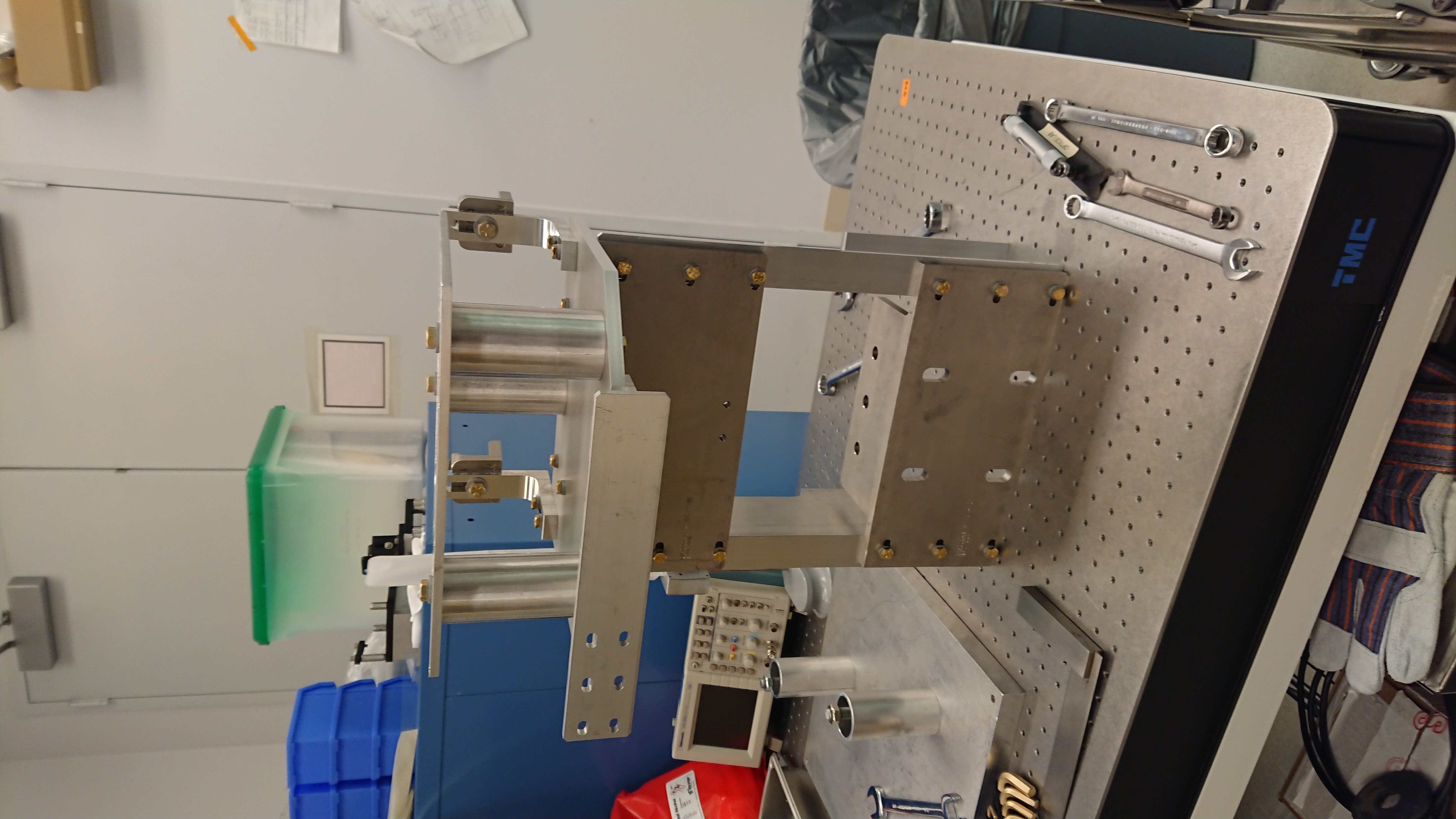
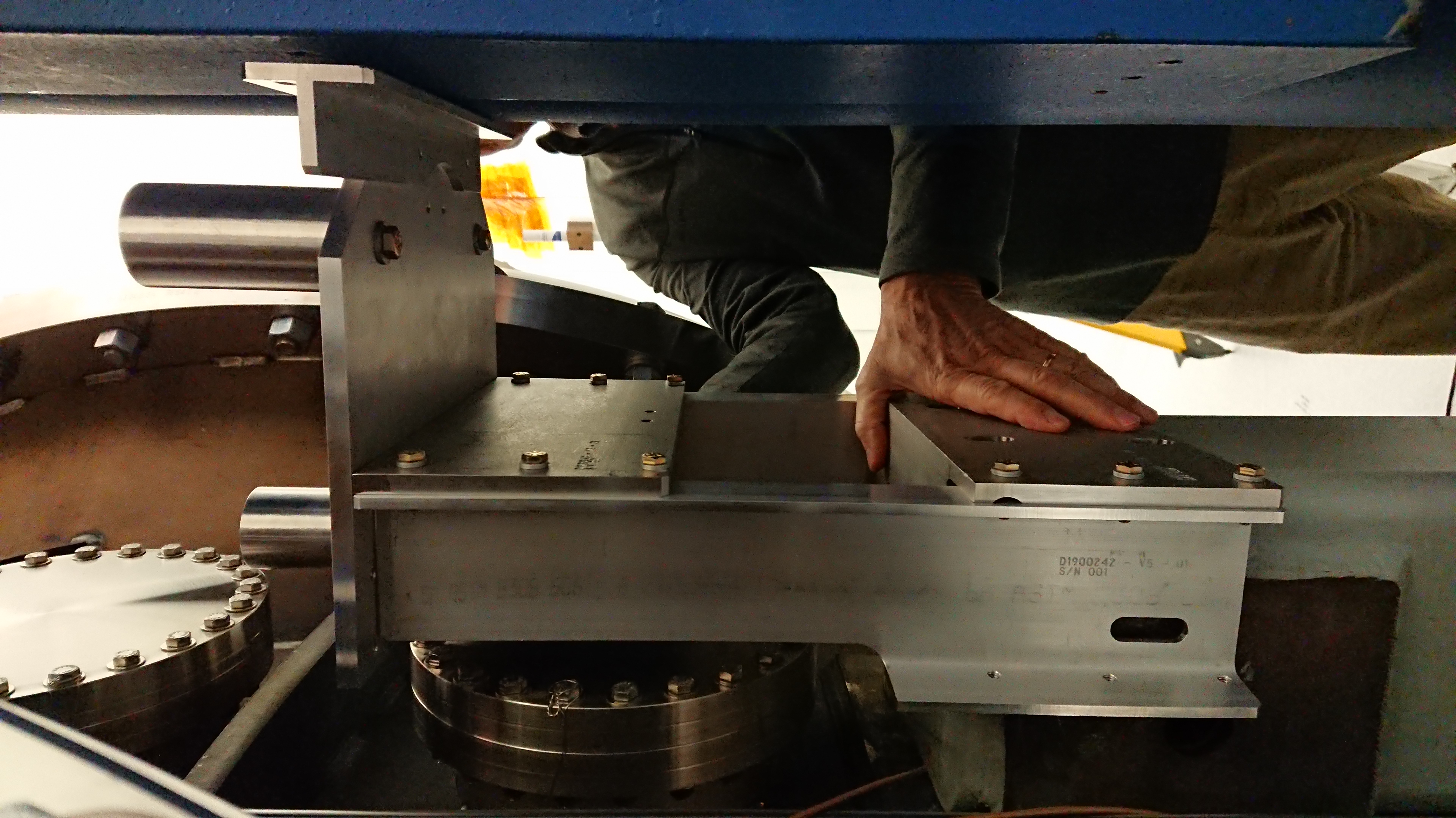
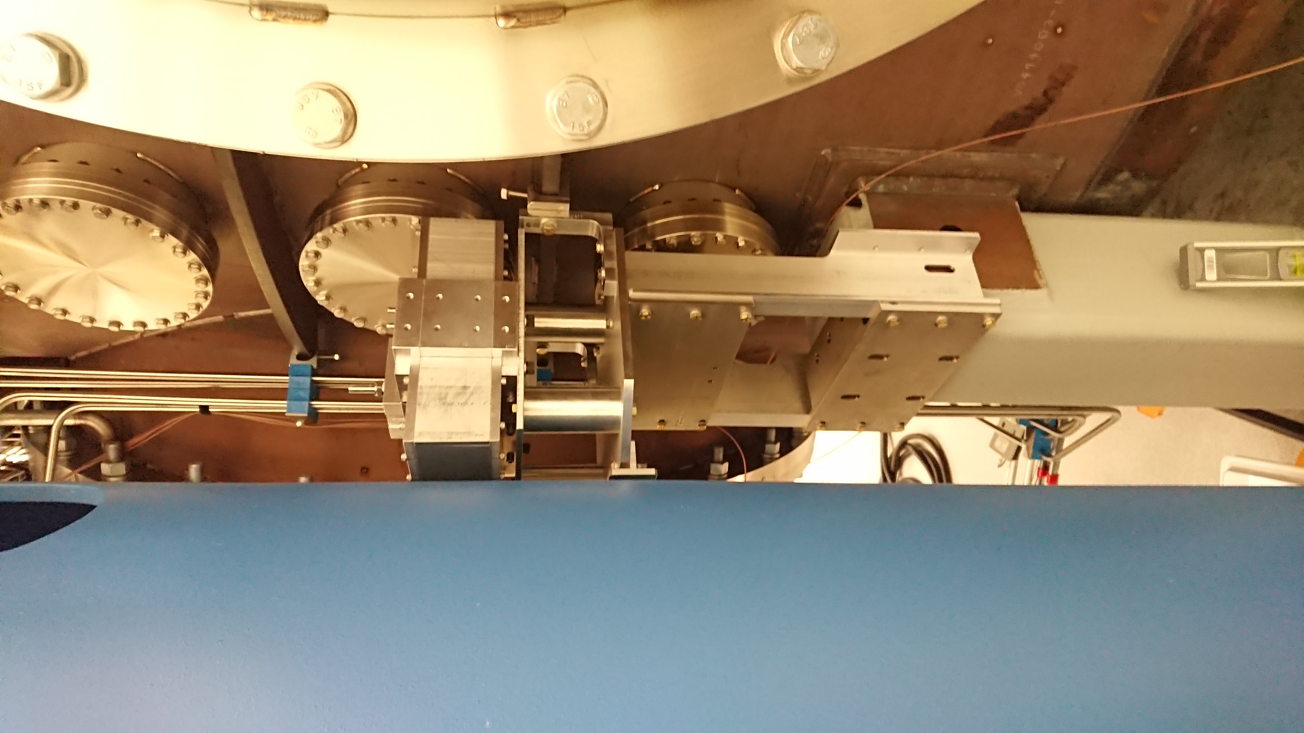
We went to the X end with the NCAL, NCAL mount and NCAL drill fixture to assess the fitment and the clearances of the hardware. The full assembly was test fitted at EX and there is sufficient clearance.

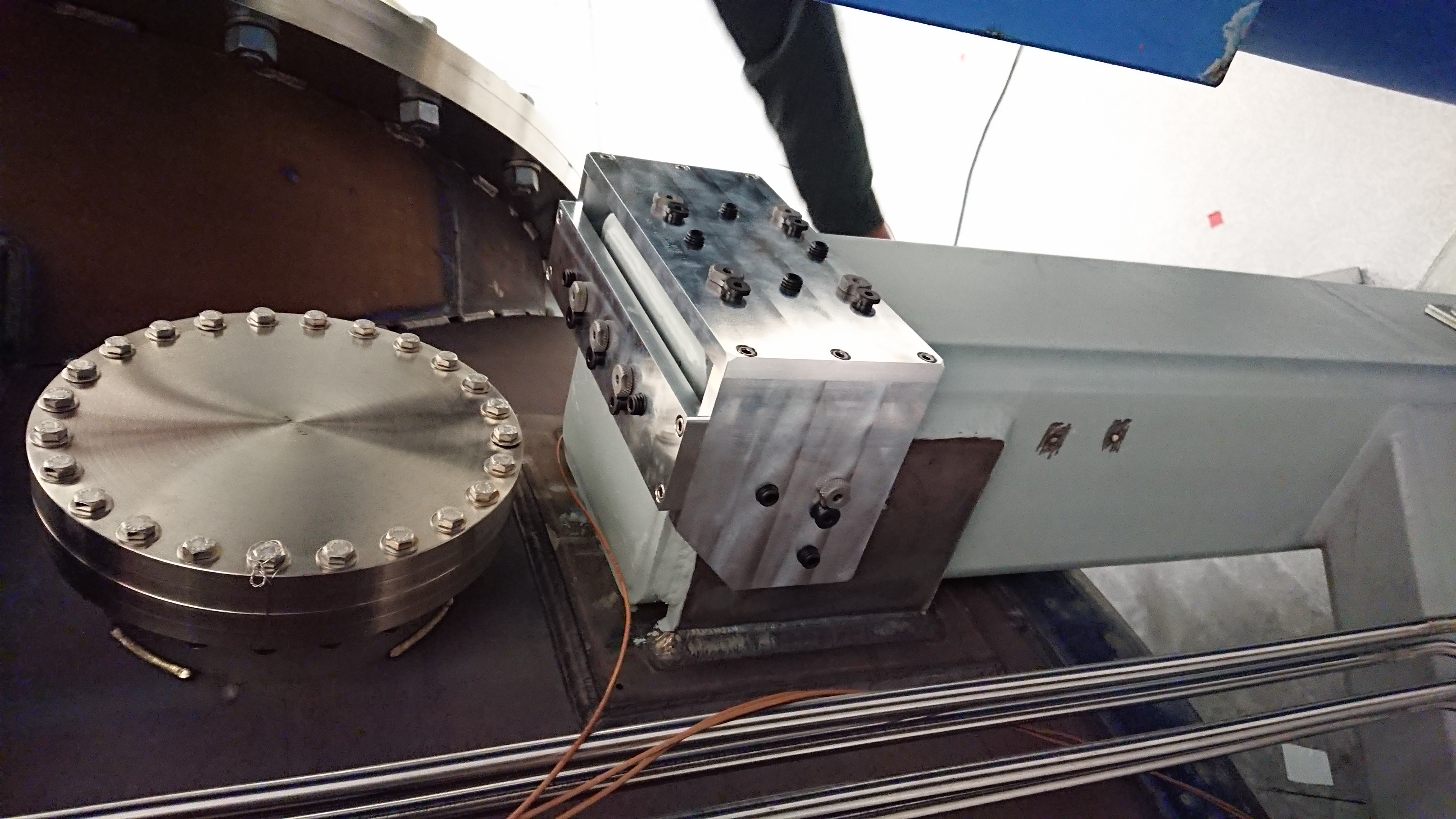
In order to set the NCAL mount upon the BSC pier, we had to remove the L brackets that would hold the Gibon clamps. The NCAL mount fits as the drawings indicate. The only discrepancy is that the NCAL mounts sits a bit lower than expected because the part of the NCAL mount that would bolt to the HEPI pier sits about 5mm low. Otherwise, the NCAL mount clears all vacuum tank flanges and ribbing as well as the resting on the BSC pier. Bolting to the NCAL mount to the HEPI pier is optional therefore, we will look to not bolting the NCAL mount to the HEPI pier.

We held the NCAL mount in place using the Gibson clamps whilst we mounted the NCAL on-top. The full assembly seems very stable however, we have concerns over the 1/4-20 bolts called out to hold the NCAL mount to the BSC pier. We will look to the Hazard Analysis form to see of we should use 3/4 bolts instead.

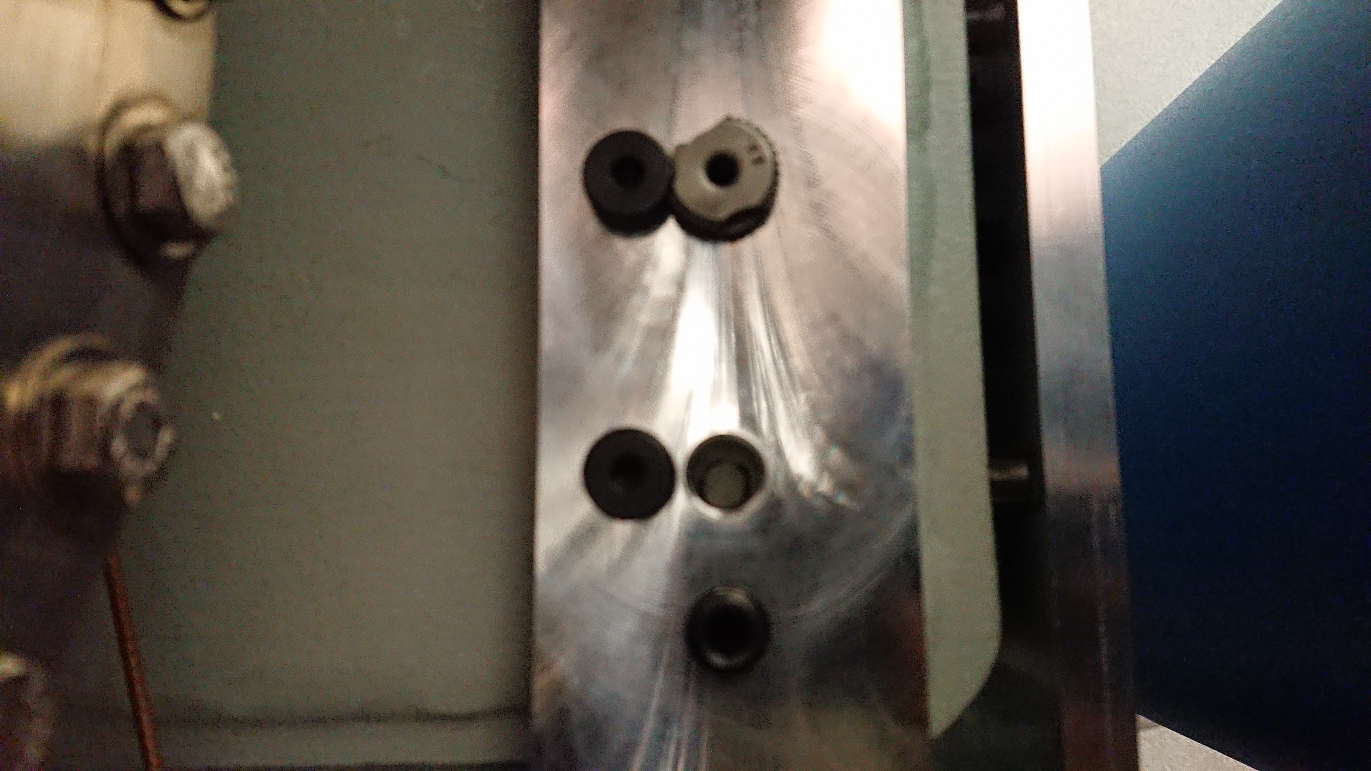
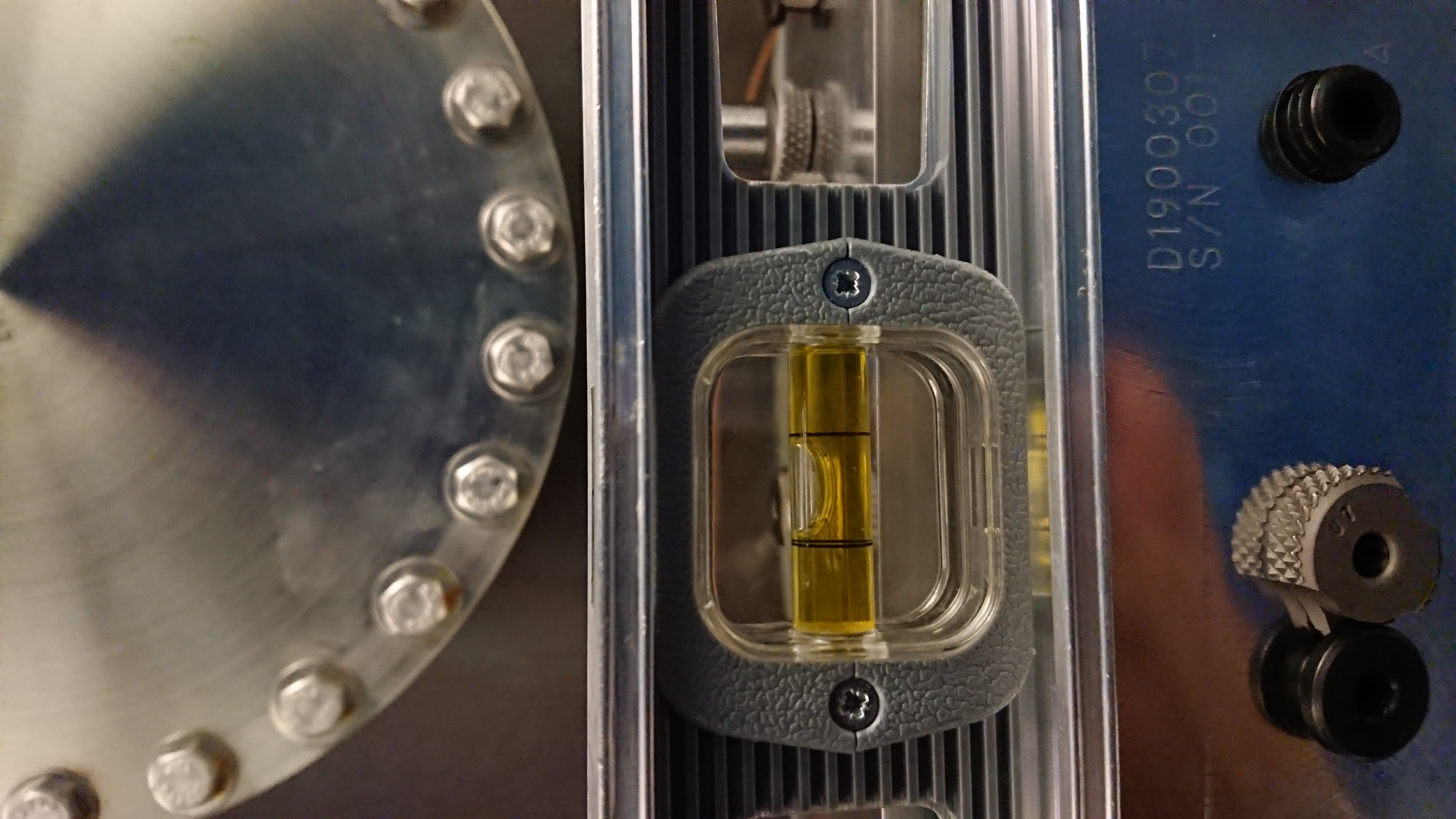
Using a permanent marker, we marked where the NCAL holes locate on the BSC pier. Once marked, we removed the NCAL mount from the BSC pier. We fitted the NCAL drill fixture to the BSC pier and adjusted the set screws until the drill fixure was level (using the bubble on a spirit level). We left the NCAL drill fixture in place before leaving the X end in preparation for drilling in the near future.

We have yet to survey the NCAL in order to get a relative location to the ETMX optic. The exact point reference point on the NCAL to survey has yet to be determined.

First Spin with Tungsten Masses

For the first time at LHO, we spun the Newtonian Calibrator with the tungsten masses installed in the rotor. This was done in the optics lab with the NCAL dog clamped to the optics bench. We tested spinning the NCAL at 1Hz, 5Hz, 10Hz, 20Hz and 30Hz. The motor ran smoothly however, the Beckoff filter drive parameters need to be double checked against the values given in LHO alog 50512. We ran the NCAL thought the Beckhoff/TwinCAT3 interface as there is no network ability in the optics lab to run using the EPICS interface (and the MEDM screen). We know this works from other tests so we are not that concerned.

At 10Hz, the apparent vibration noted in LHO alog 50961 is no longer present. At higher frequencies, the NCAL motor is more audible than when running without the masses in the rotor however this is expected. We attempted to measure the vibrations by using the accelerometer supplied by Krishna. Using a SRS755 spectrum analyser, we looked at the PSD of the accelerometer whilst the NCAL was spinning at 10Hz. We saw a peak at 10Hz in the spectrum as well as a comb of lines spaced at 10Hz. The magnitude of the combs increased with each order. It is unclear what could be causing this. We did have the accelerometer located in a different position to previous measurments. We think that the coupling from the motor to the NCAL shaft can be improved by using a flex servo coupler. This would relieve stresses associated with the motor and the NCAL shaft being slightly misaligned (either at an angular offset or horizontally offset).


Images attached to this report
H1 PSL
jason.oberling@LIGO.ORG - posted 11:44, Tuesday 08 October 2019 (52353)
PSL Power Watchdogs Reset (FAMIS 10731)

I reset both PSL power watchdogs at 18:41 UTC (11:41 PDT).  This completes FAMIS 10731.

H1 AOS
jeffrey.bartlett@LIGO.ORG - posted 11:30, Tuesday 08 October 2019 (52352)
Dust Monitor Vacuum Pump Checks (FAMIS #12997)
   Made a few minor adjustments to the air bypass on all three dust monitors vacuum pumps. They are all now operating within spec. All temperatures were right where they should be. Saw or heard no evidence of problems with any of the pumps.  

   Closing FAMIS #12997
H1 SEI
edmond.merilh@LIGO.ORG - posted 11:28, Tuesday 08 October 2019 (52350)
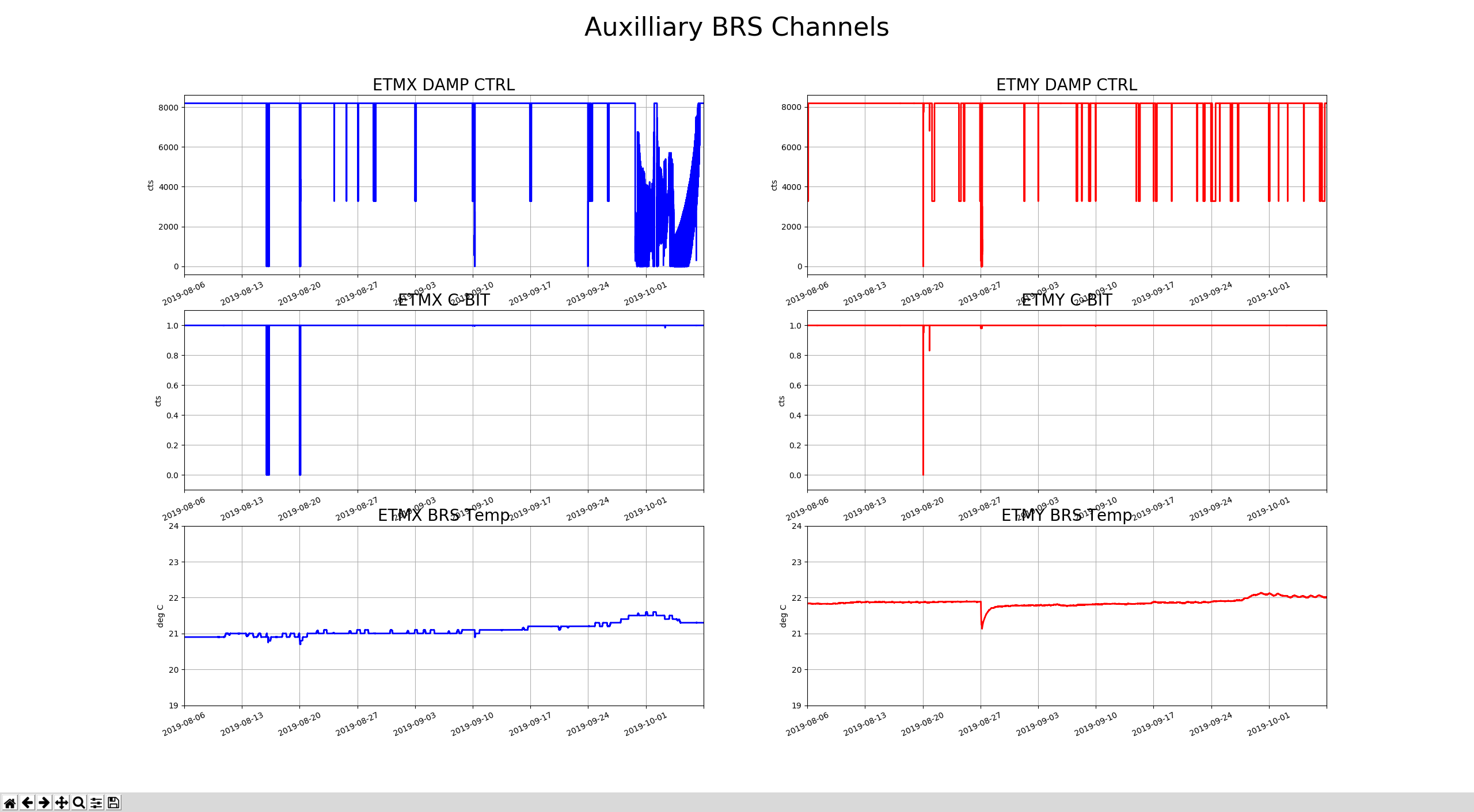
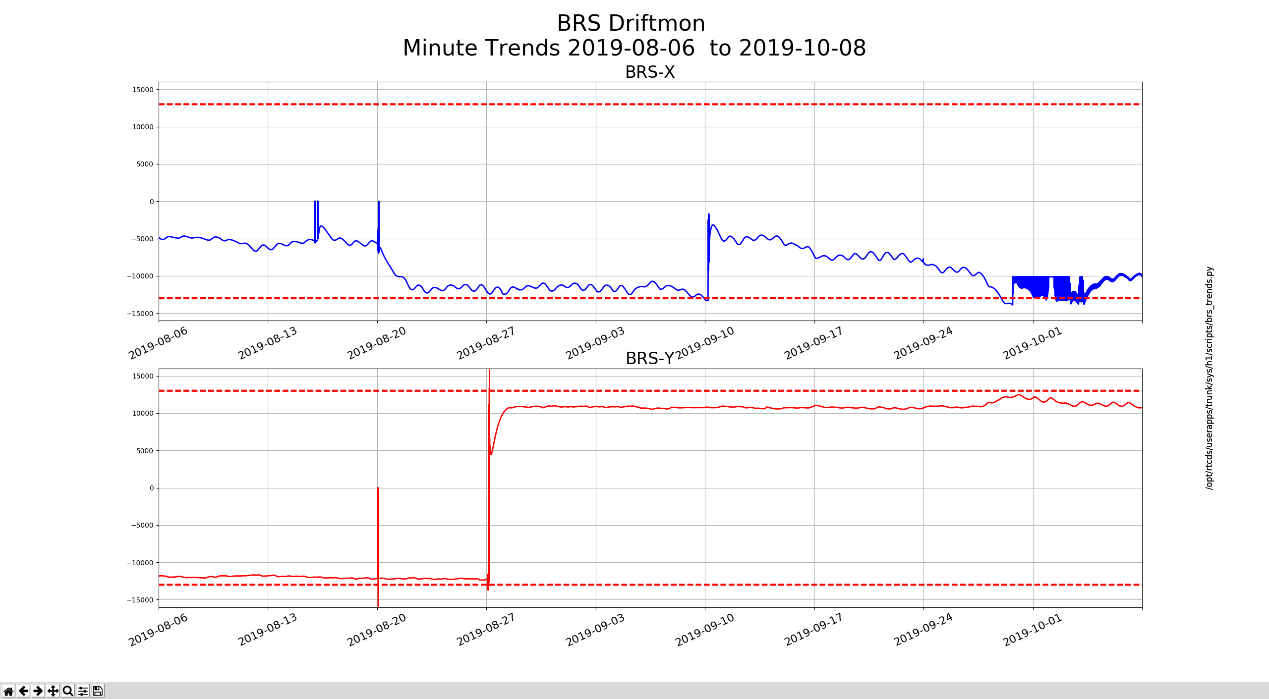
BRS Drift Trends--Monthly FAMIS #9090

BRS X seems to need attention and BRSY is getting close.

Images attached to this report
H1 CDS (ISC, SQZ, SUS)
filiberto.clara@LIGO.ORG - posted 10:57, Tuesday 08 October 2019 - last comment - 17:07, Tuesday 08 October 2019(52349)
HAM6 Ground Loop Check

Ground loop checks for SUS HAM6 complete.

Same issues with ZM1 and VOPO as seen in last November's vent, alog 45409.

HAM6:
ZM1 (Cable label SUS_SQZ-20) Pin 2 shorted to ground
VOPO (Cable label SUS_SQZ-2) Pin 13 shorted to ground

List of cables tested:

H1:SUS_10 (OMC), H1:SUS_11 (OMC), H1:ISC_236, H1:ISC_237, H1:ISC_238, H1:SQZ_1, H1:SQZ_2, H1:SQZ_20, H1:SQZ_21, and H1:SQZ_30.

Comments related to this report
filiberto.clara@LIGO.ORG - 17:07, Tuesday 08 October 2019 (52360)

Ground loop checks for ISC HAM6 complete.

Notes on method used for testing cables:

Checked Pin 13 and shield are tied together. Checked that all pins are not tied to chamber GND.

ISC_307 When testing cable disconnect ISC_404 (OMC QPD)
ISC_404 Passed
ISC_409 Pin 13 and shield not connected
ISC_232 Currently not used
ISC_233 Pins 3&4 shorted in-chamber. Pin 4 pulled.
ISC_234 Passed
ISC_235 Currenlty not used
ISC_265 Pins 14 & 15 connected to sheild (DB15 connector at rack)
ISC_266 Pins 14 & 15 connected to sheild (DB15 connector at rack)
ISC_316 Pin 5 not connected (DB9 connector at rack in CER)
ISC_317 Pin 5 not connected (DB9 connector at rack in CER)

alog 42281, alog 41722, and alog 45409 entries describing existing issues.

Tip-Tilt cables ISC_236, ISC_237, and ISC_238 are now in the SUS-R4 rack next to HAM5.

F. Clara, K. Kawabe

H1 PSL
edmond.merilh@LIGO.ORG - posted 09:34, Tuesday 08 October 2019 (52348)
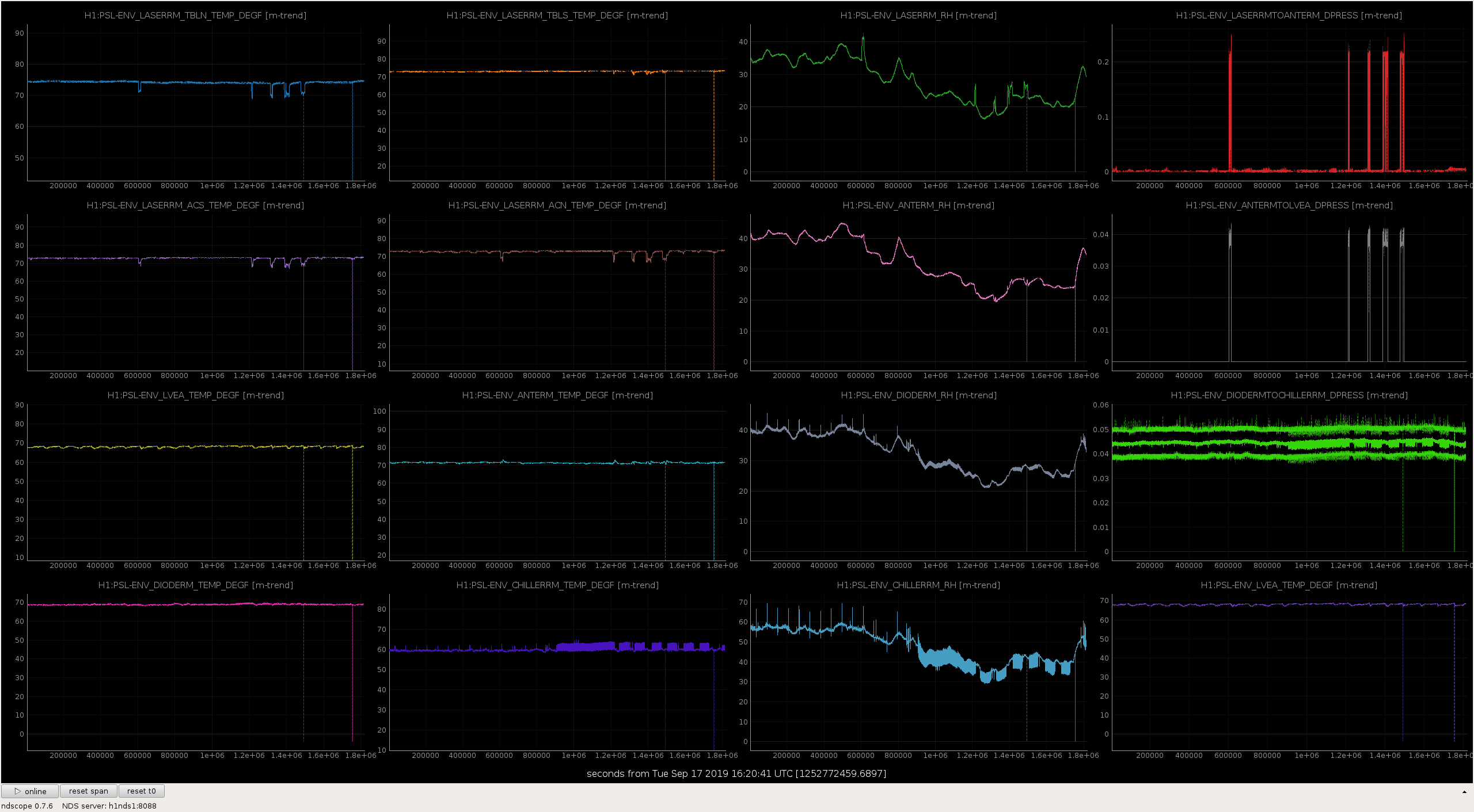
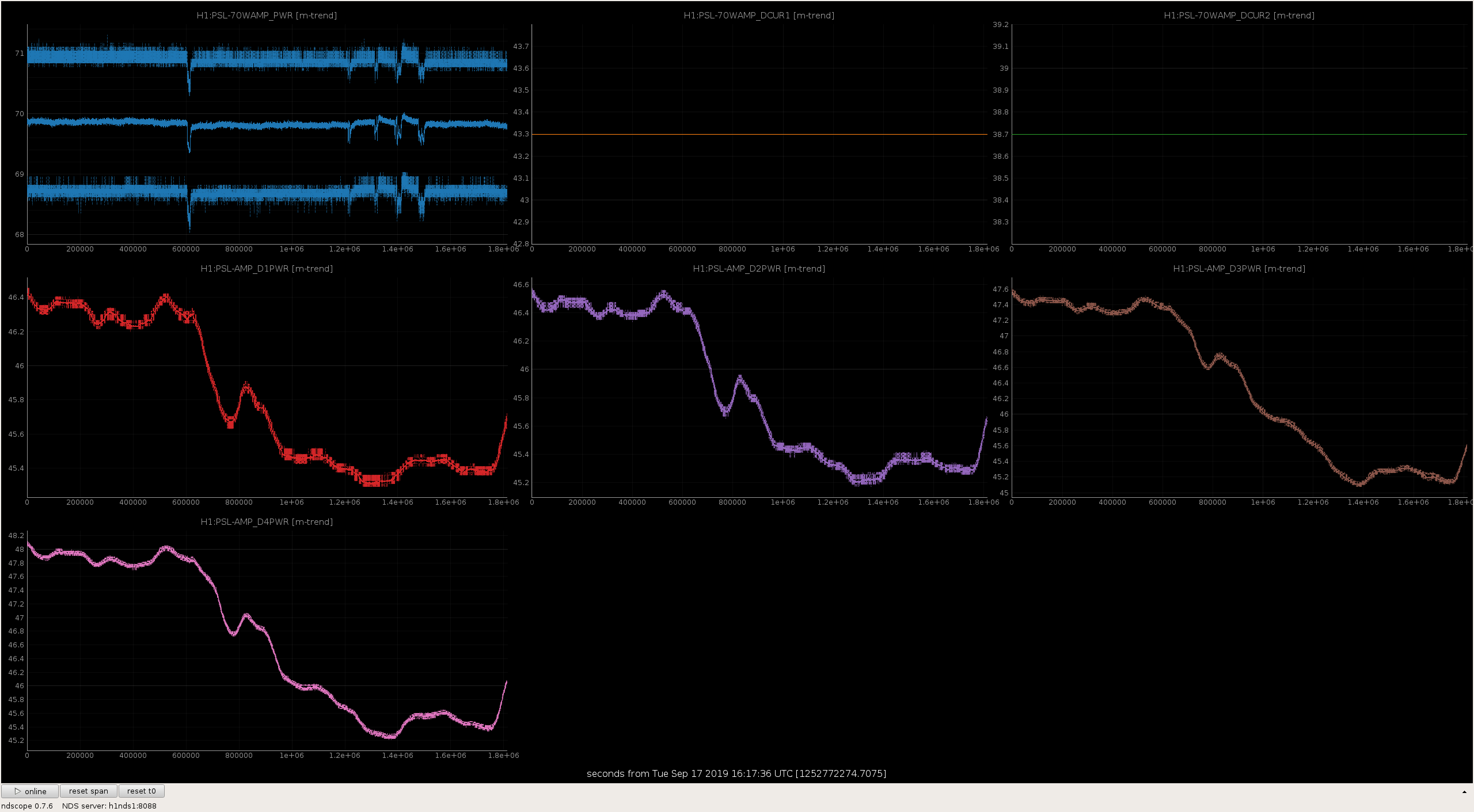
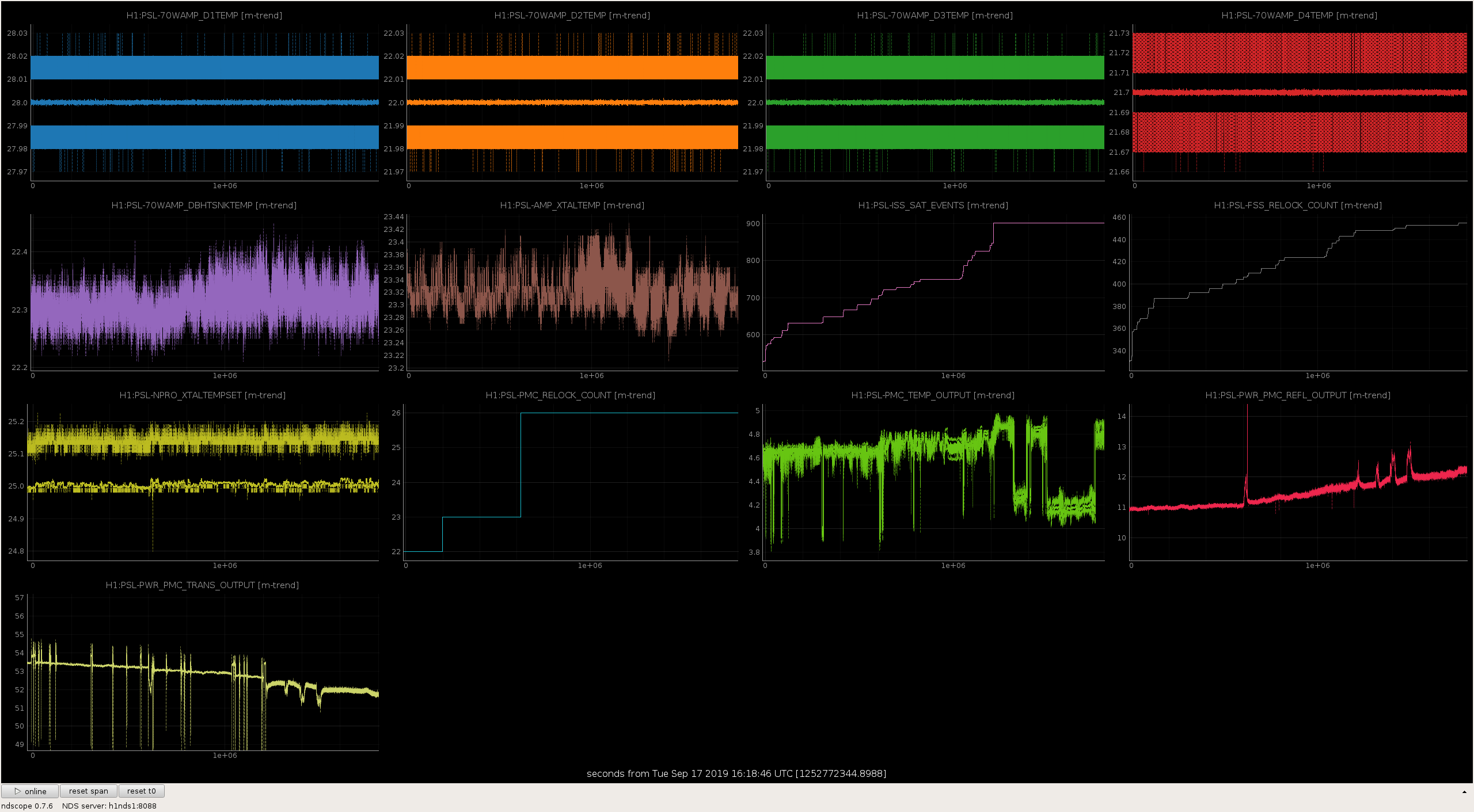
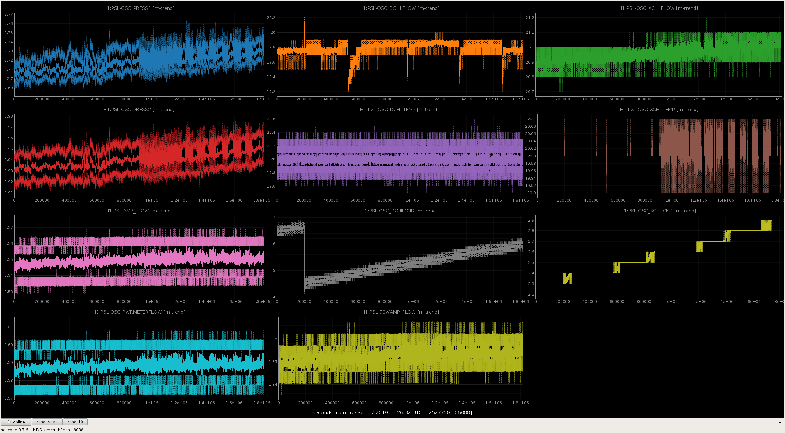
PSL Weekly Report - 10 Day Trends FAMIS #10628, 29, and 30

Attached are trends from the past 3 weeks.

Images attached to this report
H1 CAL (CAL)
timesh.mistry@LIGO.ORG - posted 22:34, Monday 07 October 2019 (52317)
NCAL Update -- NCAL Assemble

[Rick Savage, Jeff Kissel, Patrick Thomas, Timesh Mistry]

Delayed post for 04th October 2019

Assembly of the NCAL

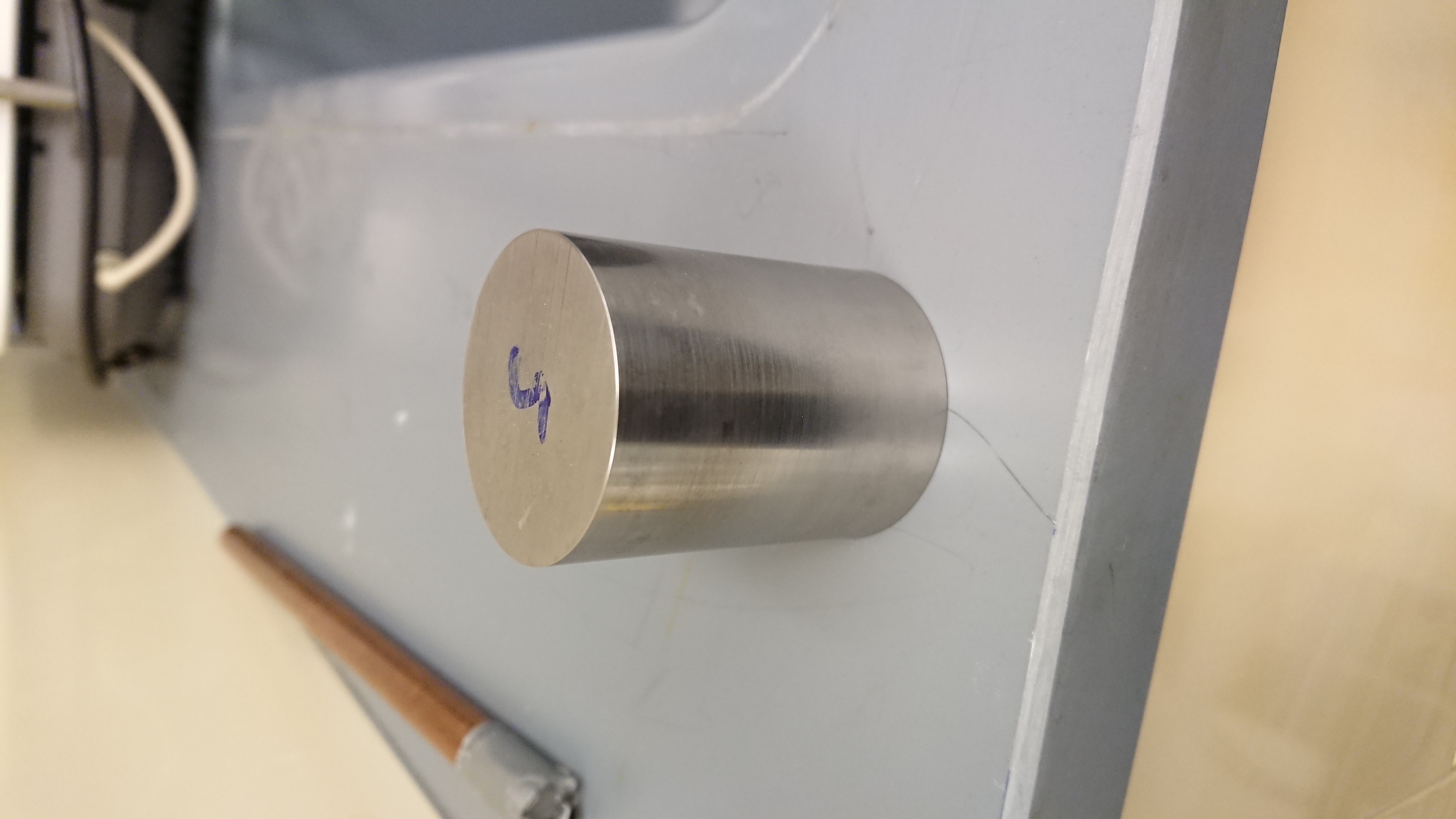
Installing the Tungsten Masses

We initially put the NCAL rotor into the oven, preheated to 70 DegC, to try and test fit the NCAL masses. We left the rotor in the oven for around 30 minutes and tried inserting the masses into the NCAL rotor. The process of test fitting was to try and place the tungsten masses into the allocated holes, without fully dropping them in, to see which of holes and masses would require some polishing. We were careful to place the tungsten masses in as straight as possible such that the sharp edges of the tungsten masses would not damage the NCAL rotor bores any further. All the masses were not able to fit inside their allocated hole prior to the NCAL rotor being baked. Mass #4 was able to slip into its' hole without resistance however, the remaining masses were not able to slip into their holes. The NCAL rotor was removed from the oven and allowed to cool before the rework comensed.

It was already known the mass and hole #1 were going to be problematic. From the first installation and removal of the NCAL masses (given in LHO alog 505012):

Mass #1 was a LOT more difficult than expected, going in and going out.
Needed aggressive hammering and dedicated heating to get it out.
Remember -- the slugs were asked to be ~10 um but came back from the shop much closer.

When inspecting hole #1, there was large scoring within the hole as well as, many sharp (protruding) surfaces. Apart from hole #4, the remaining holes also had rough surfaces. We used 1000 grit wet and dry sandpaper to remove the rough surfaces. For future design, the tungsten masses should have leading edges (much like a dowel pin) to allow smoother installation and removal of the masses and would reduce the risk of damaging the surface of the rotor bores.

The tungsten masses were polished using a scotchbrite pad. They were polished until the outer surface no longer had any surface residue from where it had binded with the aluminium rotor. In some cases, there were particulates of aluminium that needed to be removed. We did this by swiping the mass over a sheet of 1000 grit wet and dry, that was on a granite plate, in single direction. We repeated the steps until all the aluminium particulates were removed and the surfaces were smooth. The tungsten masses were cleaned with alcohol wipes to remove any final dust and debris.

We baked the NCAL rotor in an over, preheated to 70 DegC, for ~2hrs whilst the tungsten masses were left at room temperature. After the 2hrs had elapsed, the tungsten masses dropped in one by one. There was sufficient clearance such that each tungsten mass fit smoothly into its allocated hole with little to no play. Once all the masses were in, the oven was turned off and the door left open to allow the assembly to cool.

Once the NCAL was cool enough to handle, it was transferred into the optics lab and set upon the cover plates upside down. None of the masses fell out confirming the tolerances of the holes and the masses were up to spec.

NCAL Assemble

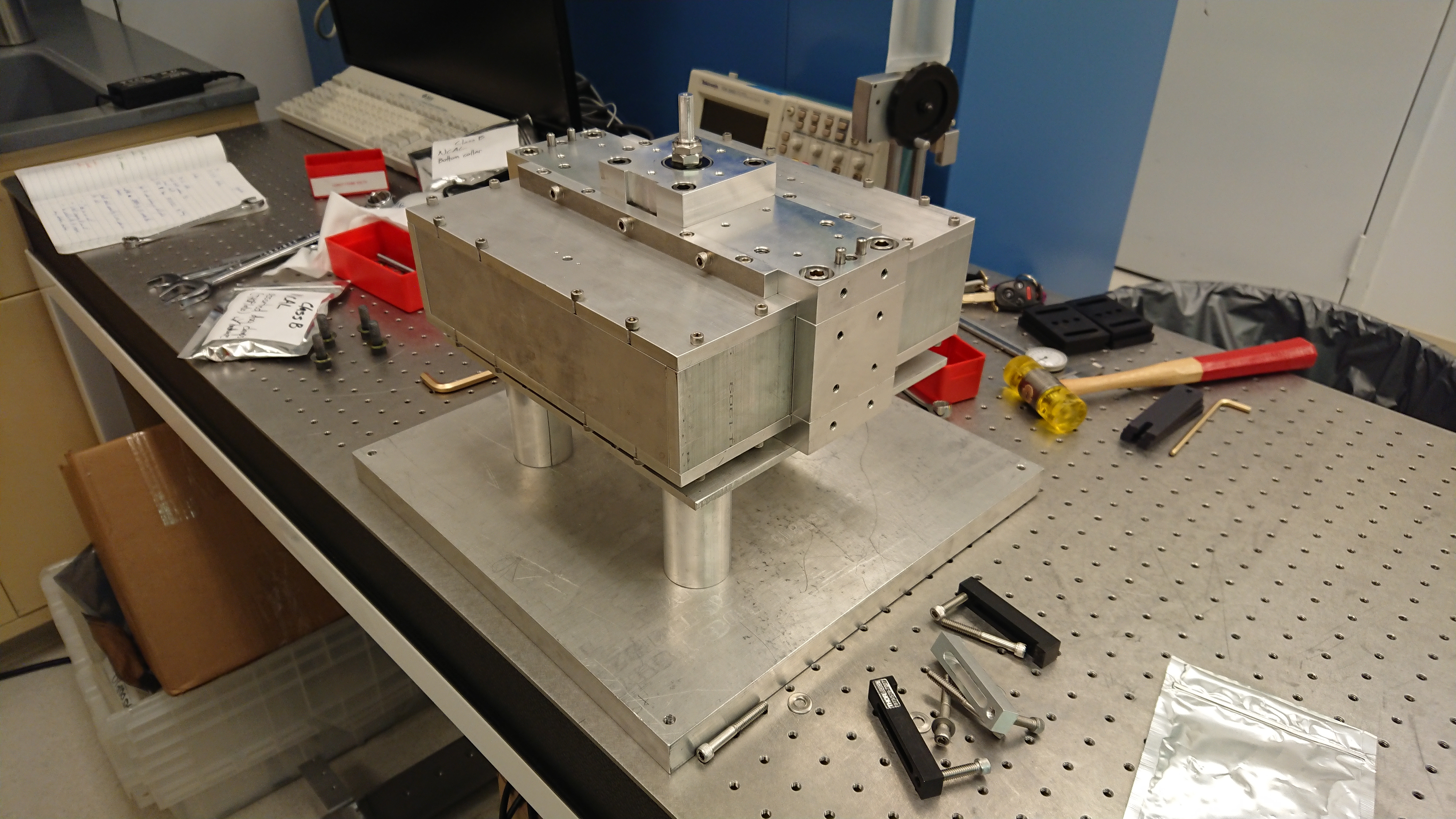
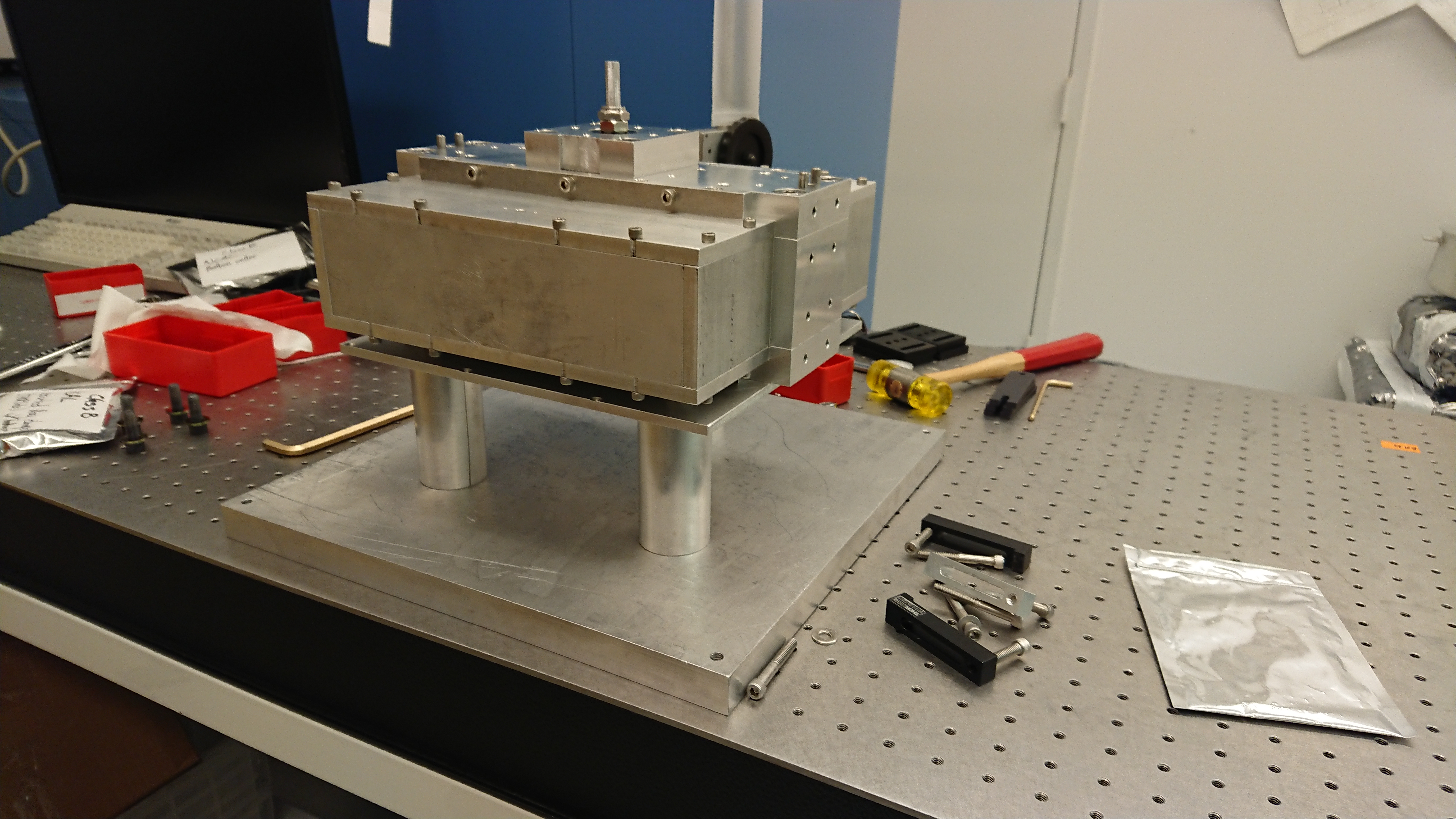
Once the rotor was uprighted, it was assembled the NCAL was fully assembled with tungsten masses. This includes the new bearing assembly (LHO alog 52301), the adjusted height of the top dowel pins for the frame (LHO alog 52272) and the remaining class B cleaned parts (LHO alog 52258) Full assembly notes will be given in a future alog. Before the covers were bolted on, we gave the rotor a spin and confirmed the bearing run smooth and there are no interference or misalignment issues.

Beckhoff/Computer Status

The Beckhoff PC supplied has a very limited storage capacity and this has caused issues with installing the other software (TwinCAT3, Windows and Visual Studio came with the unit). The PC will probably require a reset and restored to the condition it was delivered to us in as well as upgrading the internal storage capacity.


 

Images attached to this report
H1 ISC (ISC)
craig.cahillane@LIGO.ORG - posted 18:58, Monday 07 October 2019 - last comment - 23:22, Sunday 20 December 2020(52343)
DARM plant closer to Ward model, arm and SRC losses unable to fully explain the plant
This is a continuation of alog 48366.

I tried fitting the Ward DARM model to the "2019 08 19 August Spots No SRCL Offset" DARM plant measurement.

I thought SRC losses might be sufficient to explain the lowering of the Q of the DARM spring resonance.  
While the SRC losses do lower the DARM spring resonance, it also lowers the DARM pole frequency, as is expected (fDARM = farm (1 + rSRM)/(1 - rSRM)).
The level of SRC losses needed to explain the lowered DARM spring Q is far too high to be realistic (~10-15%).  These sorts of losses would lower the DARM pole far too much (~310 Hz for 10% losses).

Allowing an MCMC to try to fit the Ward model to the measurement produces the pdfs below.  

Fit Parameters:
Phi = Detuning Angle ~ 89.5 degs
Zeta = Homodyne Angle ~ 90 degs
Pbs = Power on the Beamsplitter = Input Power * PRG ~ 32 * 44 = 1.4 kW
Losses in the Arms ~ 100 ppm
Losses in the SRC ~ 1 % ??
Losses in the OMC (including OFI, tip-tilts, etc) ~ 10 %

The walkers want to lower the DARM spring Q by reducing the power on the beamsplitter and lock at some incorrect homodyne angle.  The power on the beamsplitter the MCMC wants is far too low (PRG would be ~30). 
In the posted corner plots, I have plotted my "initial guess" parameter values as the red lines.  We trust the homodyne angle and power on the beamsplitter guesses here pretty well, but the losses guesses are not well-informed.
The priors on the parameters are 

-90 < phi  > 270 [degs]
 85 < zeta > 95  [degs]
  0 < Pbs > 2000 [W]
  0 < arm_loss > 500e-6
  0 < SRC_loss > 1 
  0 < post_SRM_loss > 1


SRC losses were implemented as scattering losses in the SRC, i.e. TSRM = 32%, RSRM = 1 - TSRM - LSRC.

Dan Brown has produced a Finesse model of this same effect, with similar results to be reported soon.  We are in the process of checking the overall gain of the Ward model versus the Finesse model.

Relevant code lives in the darmplant git repo.
Non-image files attached to this report
Comments related to this report
craig.cahillane@LIGO.ORG - 12:20, Tuesday 15 October 2019 (52483)
Quick update: I've taken a look at Dan Brown's code, and we've gotten a decent agreement between the finesse model of LHO and the analytic Ward model.
Starting from Eq 3.83 of Rob Ward's thesis, we multiplied E_zeta by E_LO to get watts of DARM response, where E_LO = sqrt(20 mA/resp/QE), where responsivity = 0.856 A/W, and quantum efficiency QE = 0.98.  20 mA is the amps on the DCPD sum which is servoed using the DARM offset.
Using the same parameters in the Ward model and Finesse, I put in an additional overall scaler of sqrt(2) into the Ward model to get a overall gain matchup.  Unclear where this factor is coming from yet.

Parameters used for comparison:
Phi = 89.35 deg
Zeta = 90.0 deg
E_LO^2 = 0.0238 watts
L = 3994.4692 m
ls = 56.01 m
T SRM = 0.32
T ITMX = 0.015
T ETMX = 5e-06
Pbs = 1417 W
Arm Loss = 9e-05
SRC Loss = 0.05

Talking to Dan, the small wiggle at 4 Hz comes from a small MICH offset.  Remains to be seen if a larger MICH offset (which could be believable given the ~0.6 degree SRCL detuning we see nominally at LHO), could explain some of these discrepancies. 
Non-image files attached to this comment
craig.cahillane@LIGO.ORG - 23:22, Sunday 20 December 2020 (57547)
btw i found the factor of sqrt(2)

it comes from the definition of quadratures in Buonanno and Chen 2001, they define their quadratures like (a(w) + a^*(w)) / sqrt(2).
if you want to measure actual sideband power fluctuations at w you have to include the sqrt(2) when returning to real units of watts.
LHO VE
kyle.ryan@LIGO.ORG - posted 18:07, Monday 07 October 2019 - last comment - 18:48, Monday 07 October 2019(52342)
Miscellaneous Vertex Turbo Station installation

Chandra R., Gerardo M., Kyle R., Tyler G.

Last week we had removed the retired/outgoing (22 years in service!) iLIGO Edwards Main Turbo Pump (a.k.a. the "Vertex MTP") and installed the new, incoming, Pfeiffer Turbo Station in its place.  I installed the 208VAC service cord this morning and ran the new turbo pump (backed by its local scroll pump) for most of the day (1 x 10⁻⁸ torr after a few hours). 

Chandra R., Kyle R.

We vented the Vertex this morning to facilitate the replacement of the HAM6 septum viewport.  The measured dewpoint of the air entering the Vertex was -37C.  Later, as the septum viewport crew finished ahead of schedule, we were able to switch backing pumps such that the new turbo was backed by the iLIGO Edwards QDP80 and then began rough pumping the Vertex (only for 1 hour at the end of the day - we will resume in the morning).  I noted that the measured dewpoint of the ~ 1 1/2 psi "blow down" air exiting the Vertex prior to pumping was also -37C.  The observation that the blow down air dew point was unchanged from that of the initial air at the start of the venting is of interest.  Typically, the dew point of the blow down air is much "wetter" than that of the initial vent air due to chamber door removal(s) and in-chamber incursions by people.  In the absence of chamber door removal(s) and in-chamber incursions, the air stayed dry as you would expect - brilliant! 

Comments related to this report
chandra.romel@LIGO.ORG - 18:48, Monday 07 October 2019 (52344)

It takes the vertex turbo ~7 minutes to come up to full speed with the scroll backing it. I'm noting this because we think the XBM turbo took much longer, but will time it once fully installed.

LHO VE
chandra.romel@LIGO.ORG - posted 17:55, Monday 07 October 2019 - last comment - 18:00, Monday 07 October 2019(52340)
Vented H2

Vented H2 up to air with purge air measuring -44degC dew point. As time allows this week/month we will remove the 84" doors on HAM 11,12. We will do this without a cleanroom, with purge air cranked, and cap the HAMs with shipping covers.

Bubba and Tyler craned the door hanger over the tube to east side near roll up door to store the four HAM doors until they are ready to ship out.

Comments related to this report
michael.zucker@LIGO.ORG - 18:00, Monday 07 October 2019 (52341)VE

Alas, poor H2!  I knew him, Horatio: a fellow
of infinite jest, of most excellent fancy: he hath
borne me on his back a thousand times; and now, how
abhorred in my imagination it is!

H1 SYS
travis.sadecki@LIGO.ORG - posted 15:38, Monday 07 October 2019 - last comment - 16:48, Wednesday 09 October 2019(52329)
HAM 6 Yawed Septum Viewport installed

C. Gray, G. Moreno, T. Sadecki, B. Weaver

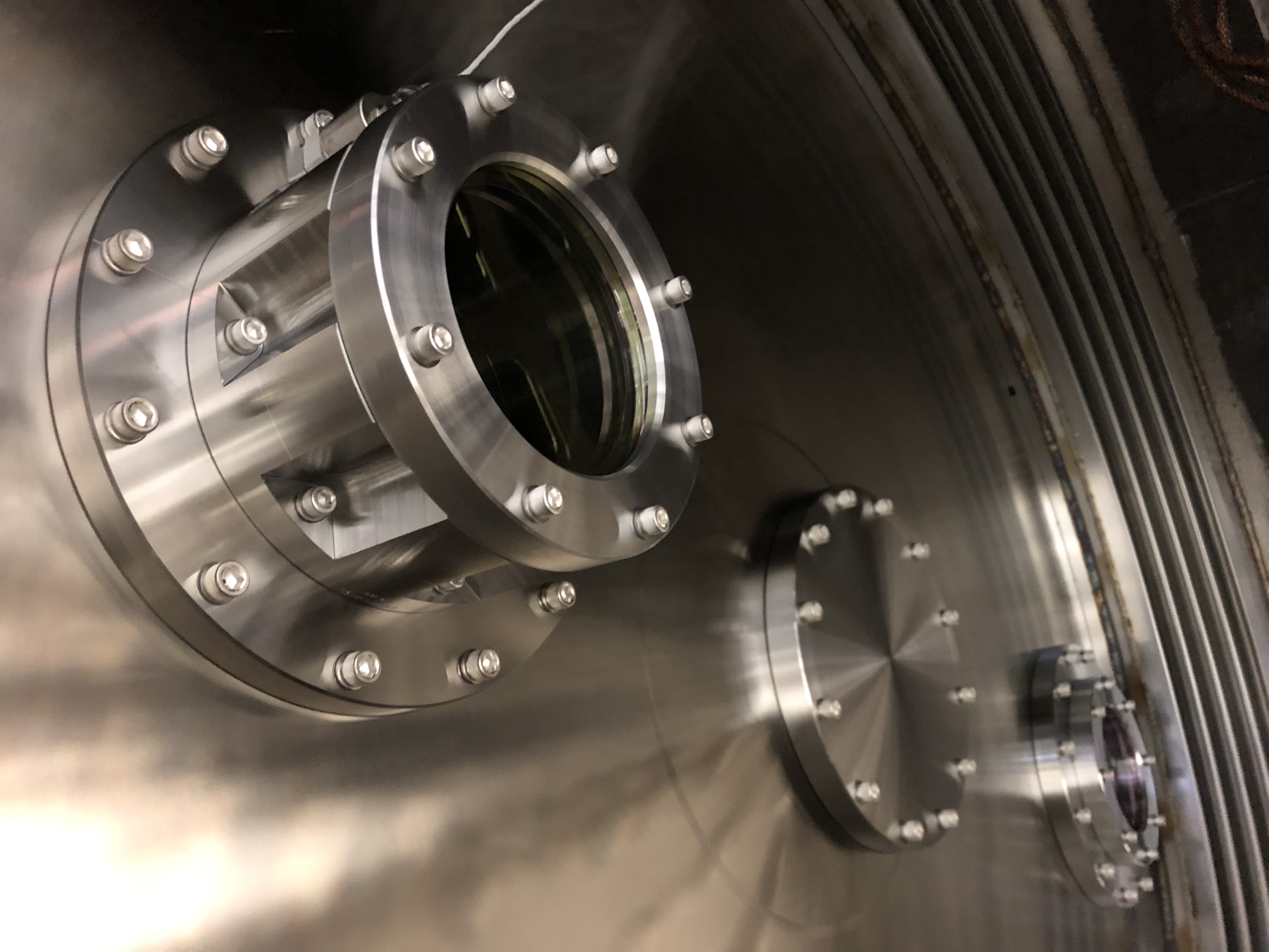
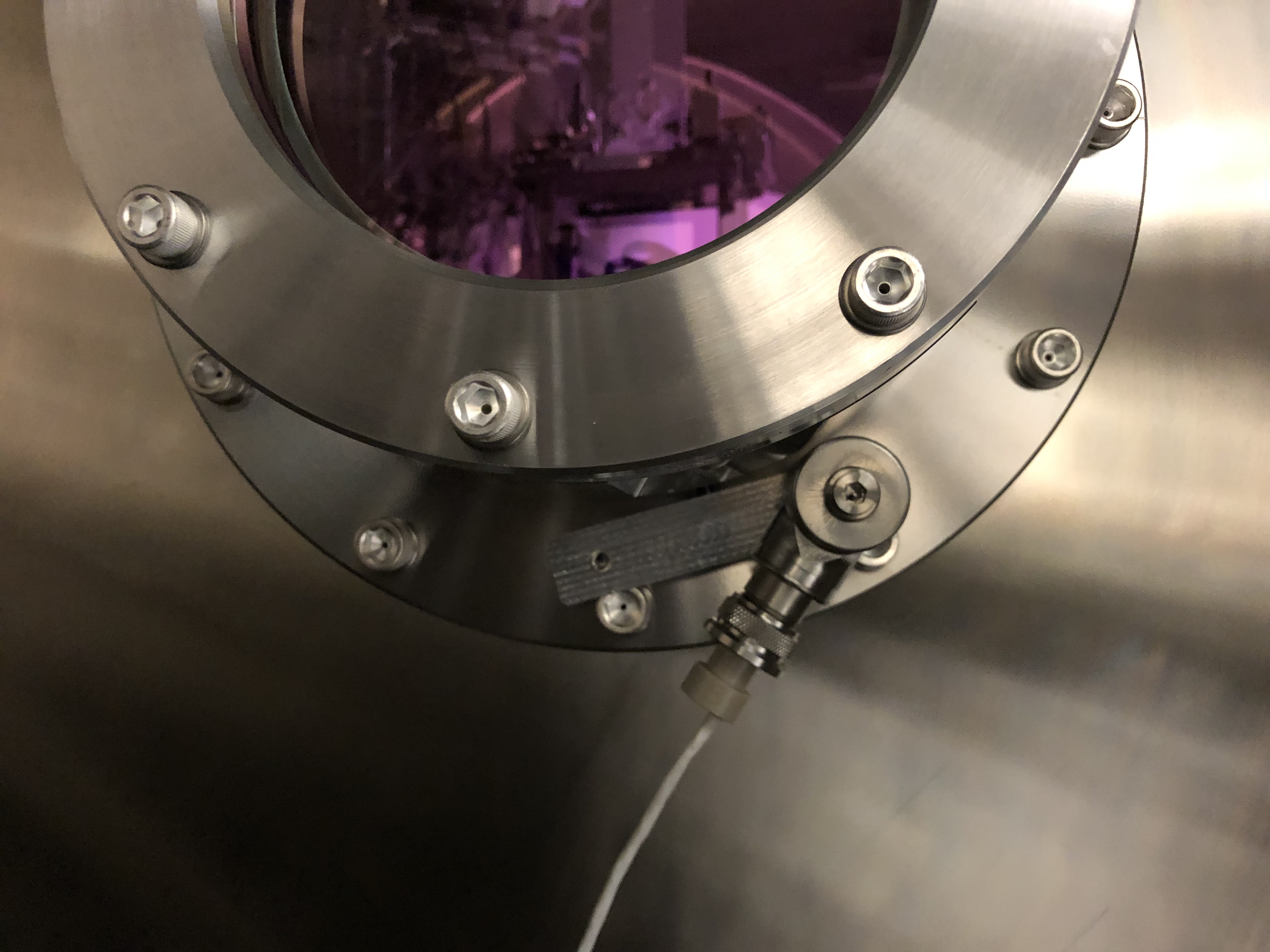
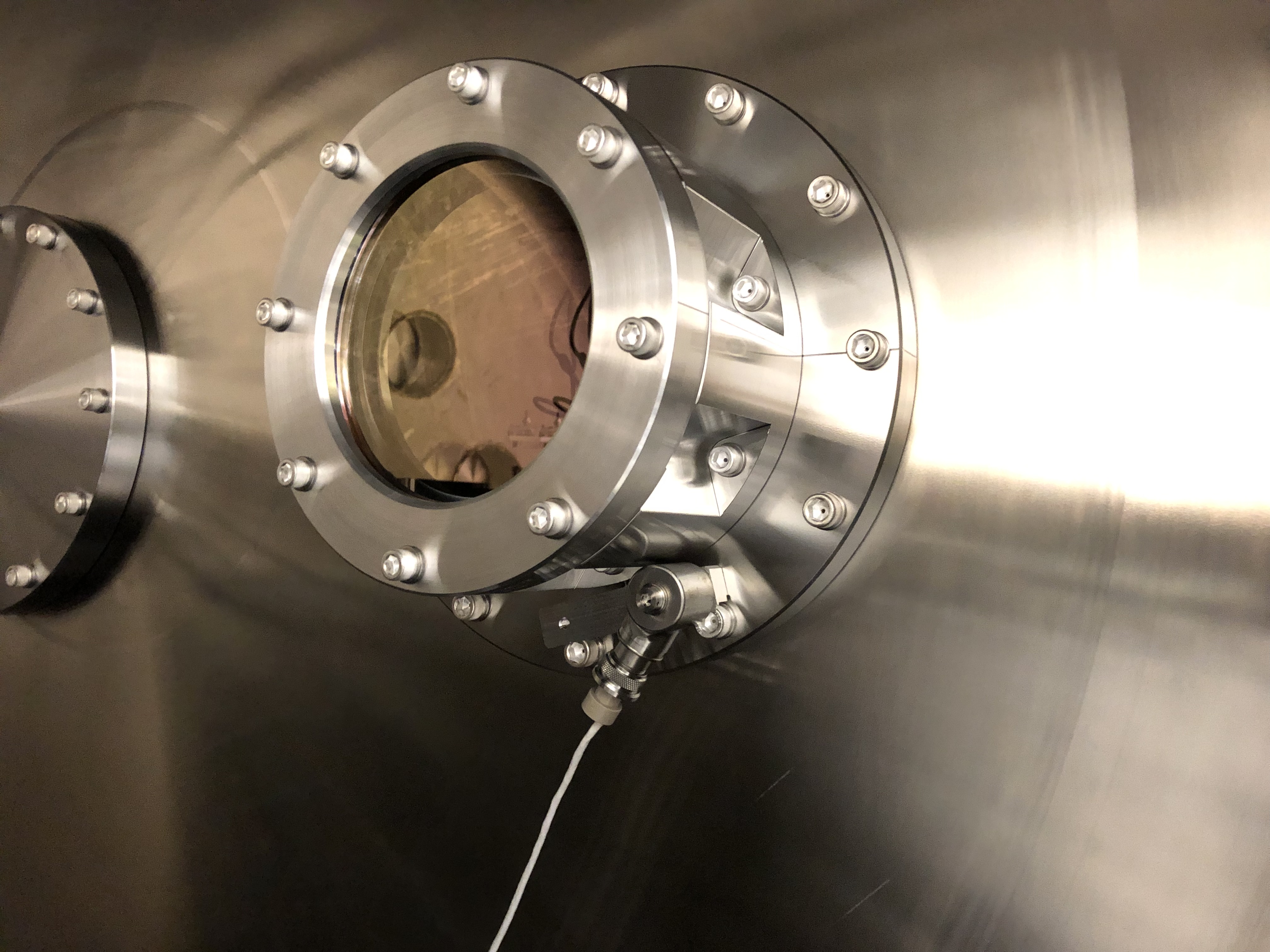
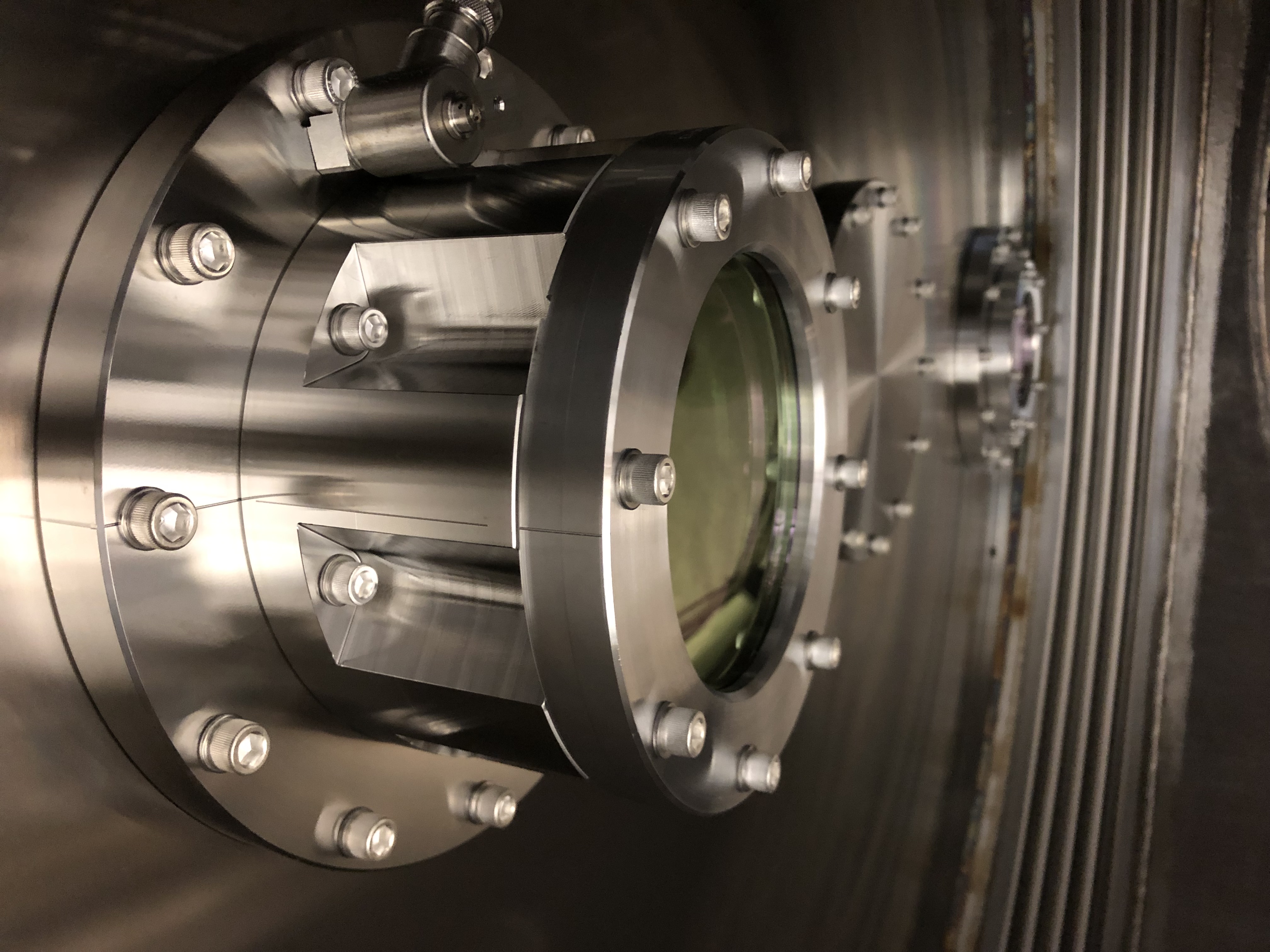
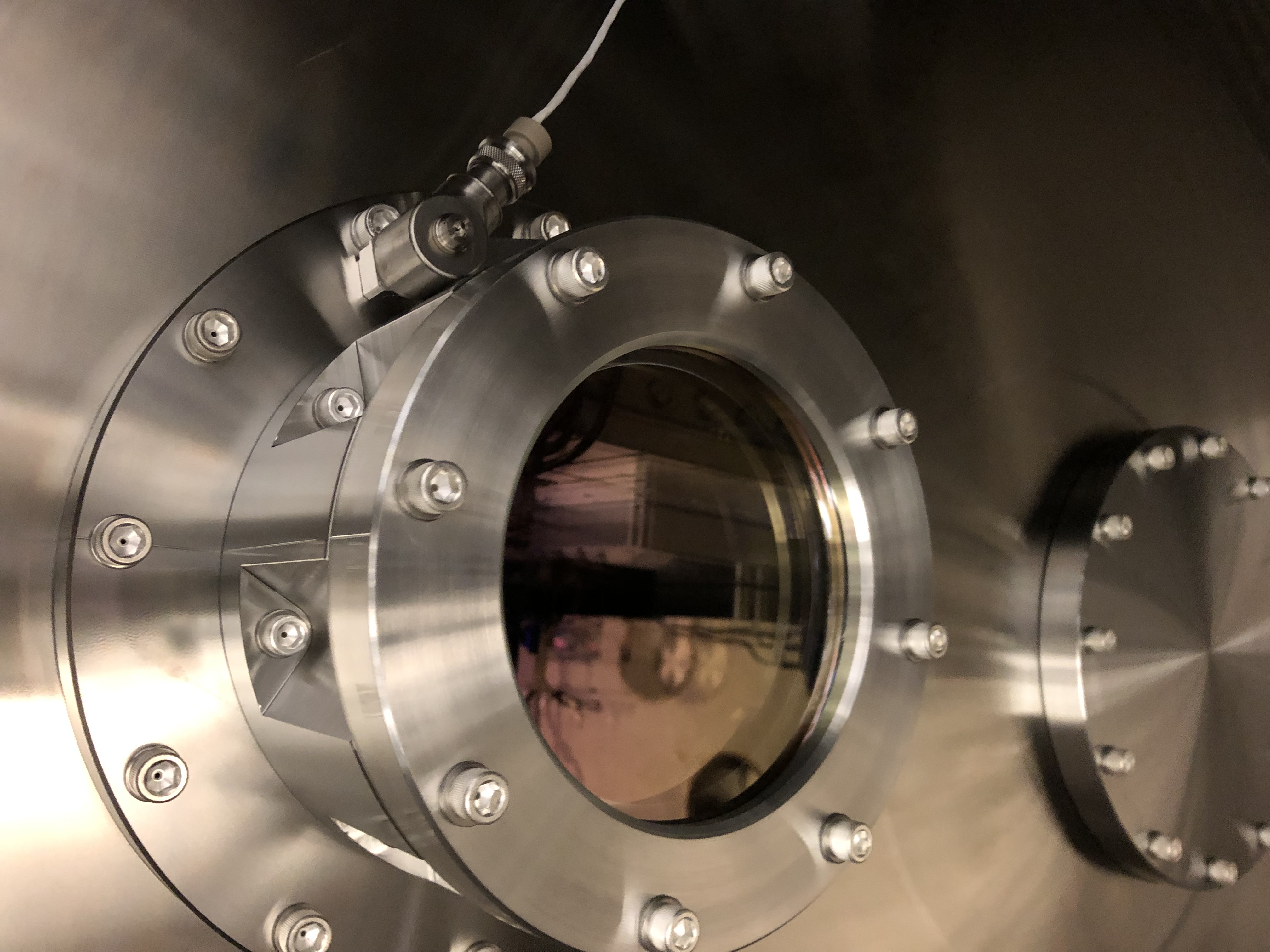
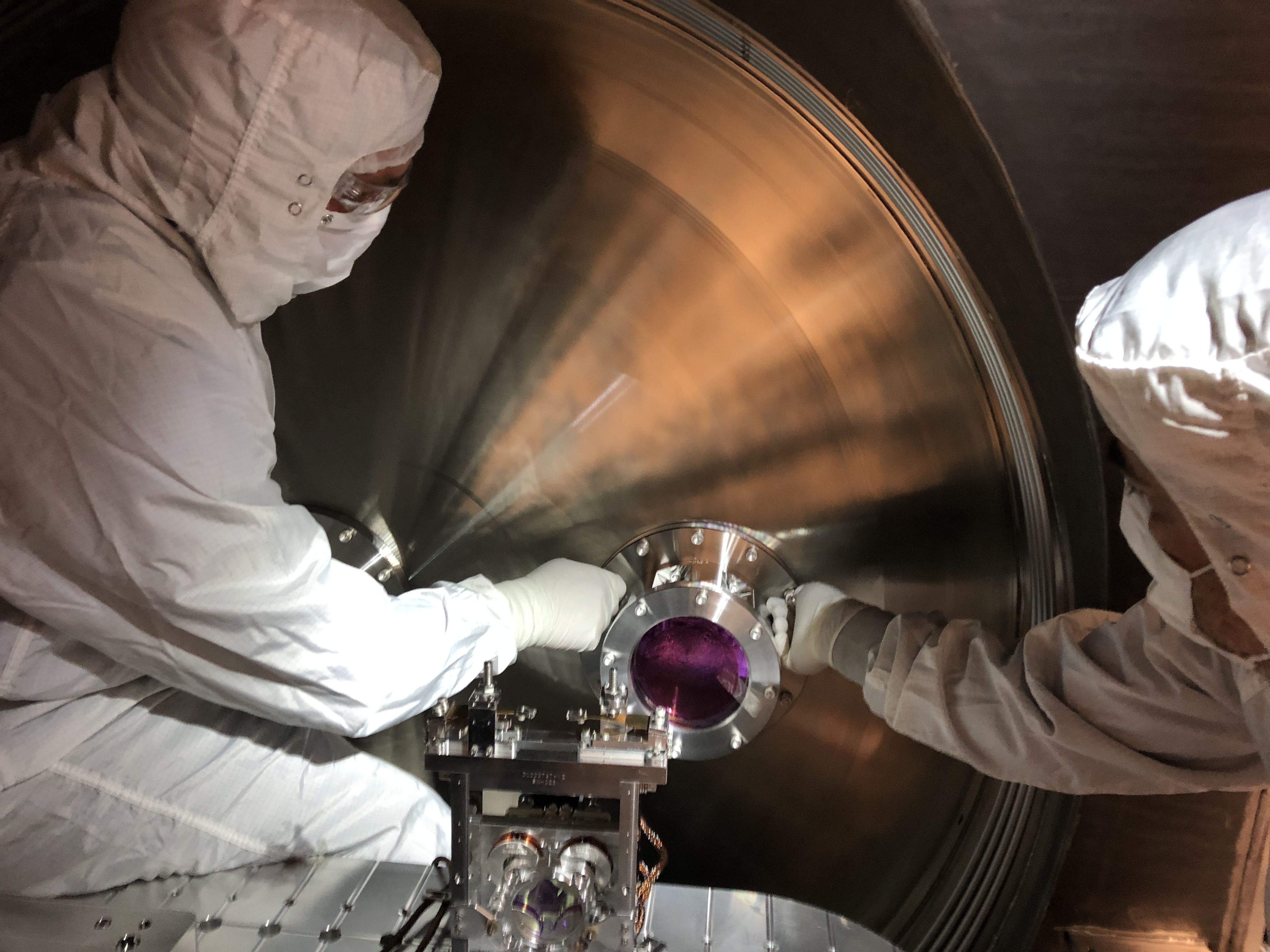
Install of the new yawed septum viewport in HAM 6 went very smoothly today.  We utilized 2 of the aligment pins (3/8-16 silver plated screws with the heads lathed down to thread diameter) that Tyler made for us.  This made the installation much easier as we had something to take the weight of the 22 kg viewport assembly while installing the mounting flange screws.  The septum window accelerometer was reinstalled in the same location it was removed from.  First Contact was removed from the inner, HAM 5 side prior to installation, and the outer, HAM 6 side was removed in-chamber after installation and torquing.  The center of the viewport aperture was inspected and was deemed free from egregious amounts of particles.  

On a related note, this was the first time I had the chance to use the new modular stair system around the HEPIs and can attest that they work much better than the previous iterations of HAM chamber stairs.  

Photos to follow.

Comments related to this report
corey.gray@LIGO.ORG - 16:04, Monday 07 October 2019 (52331)SYS, VE
Attached are photos from new yaw-ed septum viewport install at HAM6 (names of pics gives brief description of image).
Images attached to this comment
stephen.appert@LIGO.ORG - 17:37, Monday 07 October 2019 (52337)

Is it in somebody's to-do list to add a notion of the alignment pin fixturing to the documentation? Seems like that fixture should be part of the final drawing package. Let me know if a hand is needed with that.

chandra.romel@LIGO.ORG - 18:52, Monday 07 October 2019 (52345)

The "alignment" pins were a last minute tool made to help support the weight of this ~ 50 lb piece of hardware. A design improvement would be to reduce the weight by perhaps making it out of aluminum. It is difficult to get two bodies in the chamber for this maneuver and diverted the time of one of our vacuum engineers a full day.

betsy.weaver@LIGO.ORG - 16:48, Wednesday 09 October 2019 (52377)

For the record,  this is the AS viewport assembly that was removed:

ASSY-D1101092-3 HQ Wedged 6 in Septum VP
  2-253V75--BULK-C30Q002 Dupont O-Ring #AS568-253 Viton 75, V75 FKM, Inside Diameter 5.359", Cross Section 0.139"
  D1003207-V1-00-C6Q002 High quality, 6in Viewport, Viewport Spacer
  D1101005-V1-12KWZ-S5-1363-S5-1364-0015 aLIGO, high quality, .75 deg wedged, 6" Viewport, AR-1064 nm Optic
  D1101115-V5-00-0007 High Quality, 6" Viewport CLAMP, wedged
  D1101117-V3-00-0006 aLIGO Septum Viewport FLANGE


And this is the viewport assembly that was installed earlier this week:

ASSY-D1900198-001 LHO Yawed, Septum Viewport Assy
  D070082-V1-00-0006 ELI Septum Window
  D1101117-V3-00-0022 aLIGO, Septum Viewport Flange
  D1900240-V3-00-0001 aLIGO, VE, HIGH QUALITY VP, WEDGE CLAMP
  D1900327-V1-00-0002 aLIGO, VE, HIGH QUALITY VP ASSY., YAW ADAPTER
H1 SQZ
filiberto.clara@LIGO.ORG - posted 18:24, Friday 04 October 2019 - last comment - 16:27, Tuesday 08 October 2019(52318)
SQZ Controls Chassis 3 Modified

WP 8371

SQZ Slow Controls Chassis 3 modified with new Beckhoff controls for new AM AOM amplifier per E1600386-v3.

D1600509 Serial Number S1700267

F. Clara, D. Sigg

Comments related to this report
daniel.sigg@LIGO.ORG - 12:32, Tuesday 08 October 2019 (52356)

Nutsinee Daniel

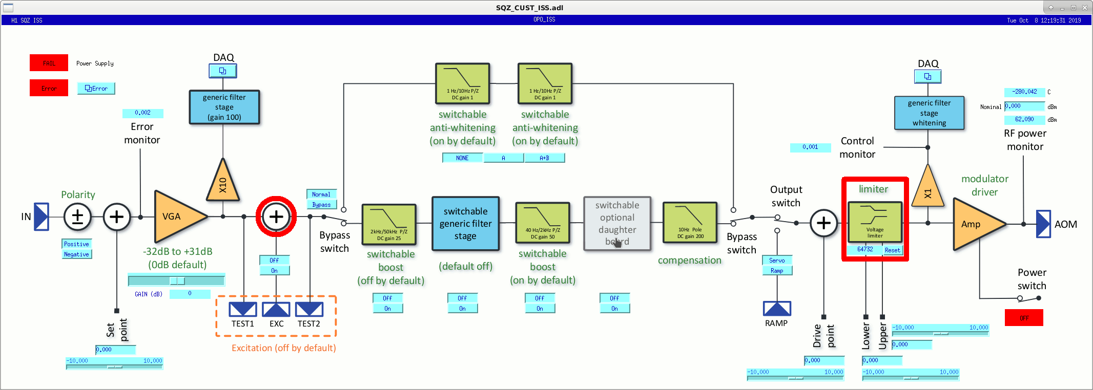
New TwinCAT/Beckhoff software was installed for the new intensity stabilization servo for the OPO pump and the CLF. Channels names are of the form H1:SQZ-OPO_ISS and H1:SQZ-CLF_ISS. A screen shot of a new medm is attched.

Finally, we hooked up the DB37 controls cable and used the tester to verify that the controls interface is working. All channels are ok.

Images attached to this comment
daniel.sigg@LIGO.ORG - 12:31, Tuesday 08 October 2019 (52357)

Marc Fil Daniel

The DAQ channels for the intensity stabilization servos of the OPO pump and the CLF have been added to the SQZ front-end model. A new ADC channel concentrator (variant 2) was added in ISC-C1/U40 and the DB9 cables connected. The error and control channels of both servos are combined into a single DB9 cable and were connected to the 7th port of ADC2 of the lsc front-end.

Updated drawings here: Squeezer wiring diagram (D1700384), ADC and DAC channel usage for ISC (T1100472), ISC LVEA Equipment Room Rack Layout (D1001427), SQZ R1 rack layout (D1600511), and RF signal distribution (E1100591).

daniel.sigg@LIGO.ORG - 16:27, Tuesday 08 October 2019 (52358)

The second CLF delay line phase shifter was in the wrong rack location and in the way of the new intensity servo for the CLF. Moved the chassis up to the correct location, and removed the old AM modulated AOM driver. Dressed the new controls cables and prepared power coords for the new intensity stabilization chassis.

Displaying reports 38261-38280 of 89075.Go to page Start 1910 1911 1912 1913 1914 1915 1916 1917 1918 End