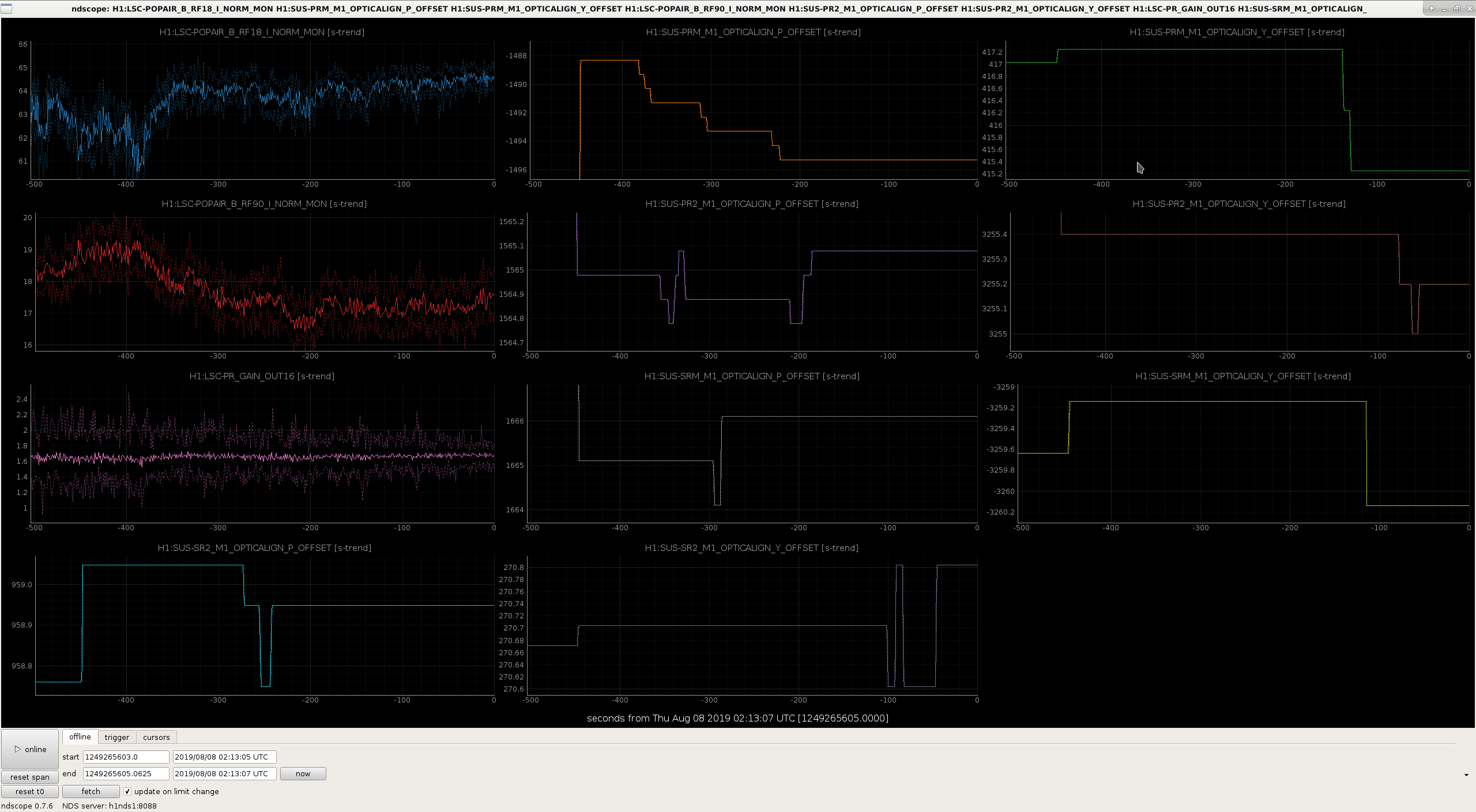
First tried working with only ETMy & TMSy, but had no luck gettting flashes above 0.72.
Decided to try an Initial Alignment, but this means Y-arm needs to atleast lock. So unlocked and tried the new knob, ITMy, but still ZERO luck. It's having a hard time just grabbing a 0:0 mode. Have tried tweaking ITMy, ETMy, TMSy with no luck. Do not see any issues on the ALS overview. The polarization is at 2, but maybe I can mess with that. I'm desperate at this point.
TITLE: 08/08 Eve Shift: 23:00-07:00 UTC (16:00-00:00 PST), all times posted in UTC
STATE of H1: Observing at 115Mpc
INCOMING OPERATOR: Patrick
SHIFT SUMMARY: relocking was an effort, with some manual alignment in OFFLOAD_DRMI_ASC, calibrations ended about 2 hours ago, Observe since then
LOG:
Activities:
Locking:
TITLE: 08/08 Owl Shift: 07:00-15:00 UTC (00:00-08:00 PST), all times posted in UTC
STATE of H1: Observing at 112Mpc
OUTGOING OPERATOR: Cheryl
CURRENT ENVIRONMENT:
Wind: 7mph Gusts, 5mph 5min avg
Primary useism: 0.01 μm/s
Secondary useism: 0.05 μm/s
Low microseism, winds under 10mph, & evening temps still at about or above 80degF.
QUICK SUMMARY:
H1's been in observing 2+hrs.
Scanning the Control Room observances:
J. Kissel
After many hours of waiting for recovery from the TCSX laser trip, and then an Earthquake, and then remaing stuggles with global alignment vs. the lock acquisition sequence, I stubbornly stuck around until I was able to complete all of this weeks standard calibration measurements.
I attach the processed results, but I haven't have much time to think about them.
From what I can initially see:
- 2019-08-08_H1_sensingFunction_mcmcModel_vs_measurement.pdf
The low frequency shape of the sensing function is quite the same as it was last week, now much more resembling a physically detuned pro-spring.
- H1_sensingFunction_PCALXvsPCALY_referenceModel_vs_allMeasurements.pdf
The low frequency response is still visible in each PCALX and PCALY in the same fashion, indicating it's still a feature of the DARM Open Loop Gain.
- 2019-08-08_H1_sensingFunction_mcmcModel_paramCornerPlot.pdf
Even though the data now more matches the model, the MCMC still has trouble fitting the data because of the high Q of the feature coupled with too few data points and the covariance between things like optical gain and optical spring parameters. You can see this reflected in the MCMC parameter corner plot, which are full of "islands" of local minima.
- 2019-08-08_MCMCTDCFs_vs_CommishEvents.pdf
That means the trend plot of MCMC parameters should be taken with a grain of salt.
- The actuators remain quite identical to the reference measurement, which is excellent -- at least we don't have to worry about that too.
Yet again, due to IFO recovery, I was not able to get any further exploratory measurements to map out the coupling of all the different knobs we have found, or suspect are causing this feature (spot position, dhard WFS gain, src asc offsets, SR3 disc heater, ITM C02 laser heating, etc.) in the face of the new global alignment position we created on July 31 / Aug 1 2019.
However, with statistics of 2, we can at least say that the feature is now relatively consistent... maybe.
The data lives here:
Sensing Function:
/ligo/svncommon/CalSVN/aligocalibration/trunk/Runs/O3/H1/Measurements/FullIFOSensingTFs/
2019-08-08_H1_DARM_OLGTF_LF_SS_5to1100Hz_15min.xml
2019-08-08_H1_PCALY2DARMTF_LF_SS_5t1100Hz_10min.xml
2019-08-08_H1_PCALX2DARMTF_LF_SS_5t1100Hz_10min.xml
2019-08-08_H1_PCALX2DARMTF_BB.xml
2019-08-08_H1_PCALY2DARMTF_BB.xml
2019-08-08_H1_OMCDCPDSUM_to_DARMIN1.xml
Actuation Function:
/ligo/svncommon/CalSVN/aligocalibration/trunk/Runs/O3/H1/Measurements/FullIFOActuationTFs/
2019-08-08_H1SUSETMX_L1_iEXC2DARM_10min.xml
2019-08-08_H1SUSETMX_L1_PCAL2DARM_8min.xml
2019-08-08_H1SUSETMX_L2_iEXC2DARM_12min.xml
2019-08-08_H1SUSETMX_L2_PCAL2DARM_6min.xml
2019-08-08_H1SUSETMX_L3_iEXC2DARM_12min.xml
2019-08-08_H1SUSETMX_L3_PCAL2DARM_6min.xml
Processing scripts live here:
Sensing Function
/ligo/svncommon/CalSVN/aligocalibration/trunk/Runs/O3/H1/Scripts/FullIFOSensingTFs/
process_sensingmeas_20190808.py
plotMCMC_vs_GDSTDCFs.py
process_sensingmeas_manydates_wPCALX.py
Actuation Function
/ligo/svncommon/CalSVN/aligocalibration/trunk/Runs/O3/H1/Scripts/FullIFOActuationTFs/
process_actuationmeas_20190808.py
with
/ligo/svncommon/CalSVN/aligocalibration/trunk/Common/pyDARM/src/
actuation.py rev 8129
sensing.py rev 8144
I'm not confident that using data below 30 Hz is the correct approach for fitting an accurate optical gain and cavity pole frequency, two parameters we think that the model actually fits correctly for and is able to track well. If I restrict the MCMC fit to the frequency range [30,5000] Hz, then we find different optical plant parameters, albeit at the cost of poor fit at low frequencies. We are not confident in the model anyway at low frequencies. Fortunately optical plant uncertainty is not a major contributor to response function uncertainty at low frequency. Below are the MCMC corner plot and model versus measurement and residuals. We can see that the residuals are much flatter and are minimized in the region of interest for frequencies greater than 30 Hz. Fit parameters are: Parameter | Quantiles (0.15, 0.50, 0.84) --------------------------------------------------------------------- Optical gain, H_c (ct/m) | 3.114e+06, 3.116e+06, 3.118e+06 Cavity pole, f_cc (Hz) | 398.9, 399.8, 400.6 Detuned SRC spring frequency, f_s (Hz) | 6.256, 6.398, 6.528 Detuned SRC spring quality factor, Q_s | 97.7, 91.55, 80.08 Residual time delay, tau_c (usec) | 0.4081, 0.9149, 1.39 ------------------------------- OR ---------------------------------- Optical gain, H_c (ct/m) | 3.116e+06 (+2464,-2273) or (+0.07908%,-0.07294%) Optical gain, H_c (mA/pm) | 4.16 (+0.00329,-0.003035) or (+0.07908%,-0.07294%) Cavity pole, f_cc (Hz) | 399.8 (+0.8064,-0.8524) or (+0.2017%,-0.2132%) Detuned SRC spring frequency, f_s (Hz) | 6.398 (+0.1299,-0.1421) or (+2.031%,-2.221%) Detuned SRC spring quality factor, Q_s | 91.55 (+639.2,-1455) or (+14.32%,-6.292%) Residual time delay, tau_c (usec) | 0.9149 (+0.4754,-0.5068) or (+51.96%,-55.39%) Optical gain is higher, cavity pole frequency is lower compared with attempting to poorly measure the low frequency deviation to our model.
[Ethan, Laurence, Dripta, Niko]
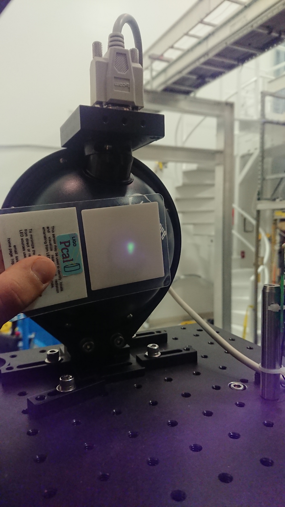
On Tuesday we performed an EY end station calibration. The measurement procedure/log and a picture of the beam alignment on the RX integrating sphere aperture are attached. The spot positions seemed slightly high compared to the last measurement on 06/04 (49868) but the phone used picks up a bit of IR light, which has fooled us before on where the spot positions actually are. I will keep an eye out for clipping on the RX aperture until the next end station calibration.
Analysis of the calibration data seems in line with the last few calibration measurements we've performed.
M. Ball
The end test masses suffer from coupling between angular rotation and linear displacement that can have an impact in DARM calibration (alog 50498). A few suggestions have been made to combat this (alog 49825) which I have modeled a bit: we can split the A2L filters into a scalar spot position term and a frequency-dependent term, and reroute the output of the L2A filters into the A2L filters.
The angle to DARM coupling goes like (for pitch only):
A->D=A2A(A2a*m+A2l)+A2L(L2l+L2a*m)
Where A2A is the digital pitch to pitch filter, A2a is the mechanical pitch to pitch transfer function, A2l is the mechanical pitch to length transfer function, A2L is the digital pitch to length filter, L2l is the mechanical length to length transfer function, L2a is the mechanical length to pitch transfer function, and m is the spot miscentering on the test mass. To remove this coupling, we can choose a digital, frequency-dependent A2L filter that makes this go to zero:
A2L=-A2A(A2a*m+A2l)/(L2l+L2a*m)
However, the dependence on m is nontrivial here. If we could remove the m-dependent term in the denominator without any significant impact, we could separate this into two separate filters:
A2L = -(A2A*L2l/A2a)*m-A2A*A2l/L2l
I have plotted this A2L filter with and without the m-dependent term in the denominator using transfer functions from the QUAD model and A2A=1 (figure 1). These filters are nearly identical for m=-15.7mm, suggesting that this separated filter can hold even for relatively large beam offsets. Separating this filter in this way should be an acceptable method for a frequency-dependent filter.
The length to DARM coupling goes like:
L->D = L2A(A2a*m+A2l)+L2L(L2l+L2a*m)
When routing the L2A filter output into the A2l and A2p mechanical transfer functions. Similar to above, terms like L2L are digital filters and terms like L2l are mechanical transfer functions. We can also reroute this output into the A2L digital filter, which makes the coupling go like:
L->D = L2A(A2A*(A2l+m*A2a)+A2L(L2l+m*L2a))+L2L(L2l+m*L2a)
Additionally, the length to angle coupling theoretically goes like:
L->A = L2A*A2a+L2L*L2a
Ideally, we can choose an “ideal” L2A filter such that this is zero and the angular loops are less impacted by the length drive:
L2A = -L2L*L2a/A2a
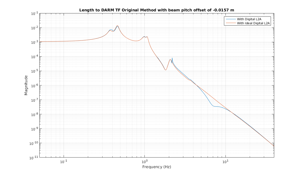
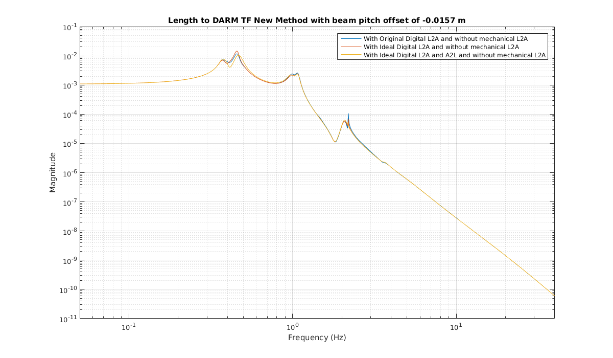
Rerouting the length to angle filter output through the angle to length filter in this loop has a minimal impact on the L2DARM coupling. I have attached plots of the coupling transfer function for routing L2P into A2a and A2l (the “original” method) and routing L2A into A2L (the “new” method). Figure 2 shows L2DARM through the original method with the current L2A filter (labeled "digital") and with the “ideal” L2A filter (labeled "ideal digital") discussed earlier. The dip in the original coupling around 7hz was responsible for calibration problems earlier in the run (alog 48738). Figure 3 shows L2DARM through the new route with the m*L2a term removed (since this term was small compared to the L2l term) with the original L2A filter, the “ideal” L2A filter and a scalar A2L filter, and both the “ideal” L2A and A2L filters discussed so far. The important note here is that in the original route, the change in the L2A filter has a noticable impact whereas with the new route, the change in the L2A filter has a minimal impact.
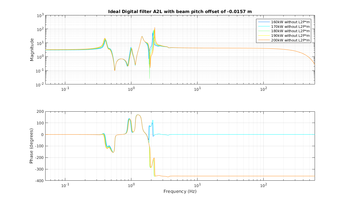
This was all done including the effects of radiation pressure using an arm cavity power of 180kW. There are plans to vary this, so I have also looked at how the “ideal” A2L filter varies with different cavity powers. Figure 4 shows the “ideal” A2L filter at arm powers ranging from 160kW to 200kW. Notice that this frequency-dependent filter is very constant in the GW band, suggesting that a scalar filter may be sufficient.
It seems lately that we pretty consistently lose lock at CARM_TO_TR the first time we try after having done an initial alignment, and then regularly make it the second time. We should look into what setting(s) we might be setting in initial alignment that we're not resetting properly until we try to acquire and then go through the DOWN state of everything.
EDIT: Sheila points out we should check settings in the Xarm IR alignment area of initial alignment, since it's probably the most likely to be causing this kind of problem.
TITLE: 08/07 Eve Shift: 23:00-07:00 UTC (16:00-00:00 PST), all times posted in UTC
STATE of H1: Lock Acquisition
OUTGOING OPERATOR: Ed
CURRENT ENVIRONMENT:
Wind: 10mph Gusts, 6mph 5min avg
Primary useism: 0.06 μm/s
Secondary useism: 0.06 μm/s
QUICK SUMMARY: lockloss at PREP_ASC_FOR_FULL_IFO, relocking
TITLE: 08/07 Day Shift: 15:00-23:00 UTC (08:00-16:00 PST), all times posted in UTC
STATE of H1: Lock Acquisition
INCOMING OPERATOR: Cheryl
SHIFT SUMMARY:
LOG:
16:11 switching SEI_CONF mode back to WINDY - noticed it had been in EQ mode for ~11 hours.
17:38 Vanessa to MX
19:43 TCSX went down
19:50 Lockloss
20:00 begin 2 unsuccessfull re-lock attempts
20:37 Initial alignment
20:44 Hugh and Jim heading out to floor to make measurements in H2 diagonal.
20:59 Hugh and Jim back
21:04 begin re-locking
22:56 Verbal Alarms seems to have lost history again -
22:58 Handing off to Cheryl
I'm leaving this here as a reminder, the VerbalAlarms wiki shows where to find the rercord of the Verbal logs. It's here:
/ligo/logs/VerbalAlarms/Verbal_logs/{year}/{month_number}/
There is a txt file for each day (in UTC times) that you can bring up in a text editor or use "cat filename" to view in the terminal.
My daily model builds were reporting errors which I tracked down to a full /var/log file system (/tmp is linked to this). While the IFO is down, I have rebooted h1build (it had been running for 106 days).
Reminder to self: h1cdsrfm is also a non-frontend diskless machine, and it too will fill its /var/log filesystem with a large messages file after several months.
I think Keith put in a solution for this at LLO.
The solution is not that sophisticated - On Tuesday, run /etc/check_all_var_log.sh on boot server - for any front-end over 21,000 (20%) ssh controls@cd /var/log sudo mv messages messages_old sudo /etc/init.d/syslog_ng restart sudo rm messages_old exit
J. Kissel, J. Oberling, T. Shaffer, J. Driggers, E. Merilh We were all excited for calibration measurements, and holding off from everything because of the GRB alert ..... and the TCSX laser power kicked off. Investigations led to the smoking gun: Spare TCS chiller was plugged in to an outlet the same circuit breaker as TSCX chiller during this morning. Spare chiller tripped the circuit a bit later, taking TCSX chiller and thus the laser out with it (because the laser watchdog tripped from having no chiller). More details to come. Interestingly, though, we saw a few interferometer build things change during this inadvertent TCS text before we lost lock. POP18 build-up dropped, but we gained about 10 Hz on the cavity pole (no change in optical gain).
Now associated with FRS 13372.
Fermi Alert - Parameters are favorable for stand-down. H1 Obeserving for only 48min folowwing a squeezer unlock.
Standown 1 hour from 18:51UTC
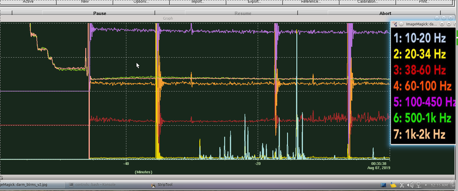
As mentioned earlier in my shift transition alog, noticed increased noise on H1 through various computers on the wall in the Control Room. For the most part I do not recall any odd activity for the DARM bands in question (10-20 & 20-34Hz), so when they are noisy, it's pretty obvious & so then an investigation begins.
Overall there was a noticeably noisy period, then it died down (but lingered), and then went quiet...but still getting glitches. Unfortunately I only snapped screenshots of the BLRMS striptool. (I was too slow to grab screenshots of the DARM spectra as well as the MICH/PRCL/SRCL spectra.
Since this is a much different feature from the high-freq noise I observed last night, I did not run Keita's measurement.
Here is an updated summary:
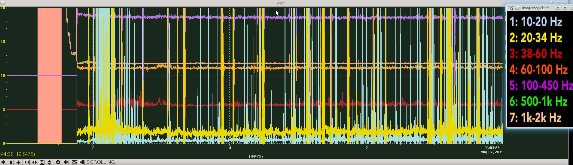
Just to give an update, we have not had the really noisy stretch like we did at the beginning of this current lock, BUT this 8-30Hz noise has not gone away either. Attached is a look at the last 7+hrs & you can see the noise has been fairly regular for the entire lock.
Scanning through Summary Pages tonight's lock as seen with DMT OMEGA looks somewhat similar over the last few days (i.e. since 8/2), and 2nd attachment is looking at 8/5 where we have a long lock which also has this low-freq noise.
Corey -- There's a brief comment in LHO aLOG 51034, and it's come up verbally in commissioning meetings, but not clearly stated in any aLOGs -- sorry for not catching you up! #OwlsAreTough Here's the story: This excess glitchiness below ~15 Hz is a result of the new alignment position of the beam going in to the OMC. We think this alignment position is making the OMC (and thus DC readout, DARM, and DETLAL EXTERNAL) more sensitive to scattered light in and around the OMC. We made this alignment change at the tail end of Aug 1 2019, as a result of the new global alignment position after losing our reference on July 30 -- which is why it's been seen since Aug 2. We're not super happy with it, but it did recover some optical gain that we lost else where. The tentative plan is to reduce the gain of the OMC ASC loops to see if this glitchiness goes away, if that doesn't work, we may consider a new alignment in to the OMC. We'll try to find a way to keep owl shifters better posted!
No worries! I figured this was proably related to recent alignment work (due to the camera bump). I didn't know a whole lot about this recovery because of being away on vacation and then did not have time to catch up on alogs last night due rough 1st half of the graveyard trying to relock H1. THANKS for explaning this though! (OK, time to sleep for tonight's shift.)
It seems that the PRM position for DRMI ASC needs to be reset to better match initial alignment. Right now, the initial alignment sets the PRM in a place that is pretty close to where it should be for full IFO (this is about -0.6 on the POP_A QPD pit_inmon signals, which looks like -0.8 at the PRC1 error signal since the POP_A QPD has a digital offset of -0.2). But, the DRMI ASC wants to put the PRM to a place where the PRC1 error signal is zero. This makes DRMI ASC a little hairy, since having the PRM move so much so fast is difficult for other dofs to follow (last night we decreased the PRC1 P gain by a factor of 10 by hand, today I've put into the guardian to reduce the gain by only a factor of 5). This then makes the full IFO ASC (including soft ADS loops) slow, because they have to move the PRM back to where the initial alignment wanted it.
When we had the DRMI ASC on, I moved the PRC1 offset to see if the buildups were okay if the PRM were closer to its initial alignment location, but the DRMI buildups didn't seem so happy. I didn't wait for full ASC convergence, and I didn't go all the way to where the initial alignment location for PRM was, so we probably need to revisit this next time we are at DRMI ASC (especially now that I see that the full IFO PRM place is quite close to where initial alignment leaves it). For now, so that we survive the DRMI ASC, I've lowered the PRC1 pit gain in the guardian to 2, from its typical value of 10. We'll probably want to speed it back up once we reset the setpoint.
Separately, for PRX initial alignment: Last night Corey had to increase the gain of PRCL by hand, but I think that is just because I had forgotten to hit 'load' on the ALIGN_IFO guardian after last night (alog 51044) re-reverting the gain to the high value. After loading the guardian today, PRX locked. However, the ALIGN_IFO guardian didn't think it was locked, since the PRM position (which had been set most recently by offloading DRMI ASC during the previous lock) was so far wrong. The guardian wanted POP_A_LF to be greater than 1.0, but it was hovering around 0.85. I lowered the 'locked' threshold for PRX in lscparams.py to be 0.5, and then the ALIGN_IFO guardian was able to align PRX as normal. Probably once we fix the DRMI PRM setpoint to match the initial alignment and full IFO positions, POP_A_LF will start out much closer to its usual locked and aligned values, so we can put the locked threshold back to its old value of 1.
I again did a teeny bit of exploring, but again it seems that if I put the POP A QPD offset to the place where the full IFO wants it, the POP18 buildup dropped a lot. So, for now I've put the setpoint 25% of the way closer to where the full IFO wants it (offset of 0.0, from old offset of -0.2, when the full IFO wants the offset to be +0.6), and the POP18 value is still pretty good. Once we reached PREP_ASC_FOR_FULL_IFO, it was also clear that the PRM was closer to the final location that the ADS system wants it, which is good.
I have accepted this new POP A QPD offset in both the safe and observe ASC sdf files.
In the end, I put the POP A QPD offset back to -0.2 as it was last night, since we've been failing at acquiring lock with other values. This acquisition we let DRMI ASC go with the old POP QPD offset, but after we offloaded the DRMI ASC Cheryl touched a few of the optics (PR2, PRM and SR2, I believe) to further improve POP18 and POP90 buildups. After she did that, the POP18 and PR gain traces looked a lot smoother than they have all day. With this alignment, we have (so far) been able to get to DC readout for the first time in several hours, and are currently increasing power.
So, I'm not sure why, but our DRMI ASC is leaving the optics in a place that isn't the most optimal alignment. When this is happening, we lose POP18 buildup as we go through the CARM offset reduction sequence. With Cheryl's nice hand tuning, we dind't really see this happen. So, we need to understand what's going on here, but for tonight we'll just let the IFO observe.
M. Ball, J. Driggers, S. Dwyer, J. Kissel We've gathered a standard set of sensing function measurements this week in the nominal IFO configuration. What may be of note -- after yesterday's computer process restart of the h1asc model (LHO aLOG 50567), and during recovery, we re-acquired the IFO *without* the SRC1 Yaw offset we've been running with since May (see LHO aLOG 49393). You'll notice in the plots below, the sensing function has changed shape to something more like a physical spring unlike what we've seen in the past. We lost lock before we were able to explore this further, but we will likely be running with this offset OFF from now on, so it'll be something interesting to keep an eye on (i.e. to see if next week's sensing function is consistent with this week's, and we'll also try actively changing this offset to see if it is yet another knob beyond spot position and ASC gain). Attached is a collection of 4 plots: Page (1): The sensing function (i.e. ratio of PCAL2DARM and DARM Loop Suppression transfer functions), compared against a new MCMC fit to establish this measurement's parameters. Note that although the cavity pole frequency is reported low, this is not the only time it's been low like this (see later, Page (4) comments). Page (2): The same sensing function measurement compared against the *reference* model Page (3): The individual measurements going in to the sensing function. Page (4): a time series trend of the MCMC fit values for the parameters of sensing function measurements throughout O3 up to today. We also began to phase and balance the quadrants of the AS_A_45 WFS (i.e. the error signal for DHARD), using the PCAL calibration line at 17.1 Hz as our "pure longitudinal / DARM" drive, minimizing that line in the I phase. Unfortunately, we lost lock just after measuring the DARM loop suppression and did not get the PCAL2DARM transfer function, so we can't show a plot of how the sensing function changed. However, from our previous work (see LHO aLOG 50498, G1901353), we have found that only the DARM Loop Suppression changes under these ASC-like changes -- and we saw no change. Raw data templates: /ligo/svncommon/CalSVN/aligocalibration/trunk/Runs/O3/H1/Measurements/FullIFOSensingTFs 2019-07-17_H1_DARM_OLGTF_LF_SS_5to1100Hz_15min.xml :: standard measurement of 1/(1+G) 2019-07-17_H1_PCALX2DARMTF_LF_SS_5t1100Hz_10min.xml :: new-ish standard measure of C/(1+G) with PCAL X 2019-07-17_H1_PCALY2DARMTF_LF_SS_5t1100Hz_10min.xml :: standard measurement of C/(1+G) 2019-07-17_H1_PCALX2DARMTF_BB.xml :: new-ish standard measure of broad-band C/(1+G) with PCAL X for testing GDS-CALIB Strain, Start Time: 2019-07-17 20:42:25 UTC 2019-07-17_H1_PCALY2DARMTF_BB.xml :: standard measure of broad-band C/(1+G) with PCAL Y for testing GDS-CALIB Strain, Start Time: 2019-07-17 20:40:19 UTC 2019-07-17_H1_OMCDCPDSUM_to_DARMIN1.xml :: standard measure of the conversion between DARM IN1 error signal in [ct] and (roughly calibrated) DCPD current in [mA] 2019-07-17_H1_ASATuneUp_DARM_OLGTF_LF_SS_5to1100Hz_15min.xml :: standard measure of 1/(1+G), but after modifications of AS_A_45 WFS quadrant phases and gains. processing scripts: /ligo/svncommon/CalSVN/aligocalibration/trunk/Runs/O3/H1/Scripts/FullIFOSensingTFs/ process_sensingmeas_20190717.py :: first three plots plotMCMC_vs_GDSTDCFs.py :: last plot using rev 8028 of function library, /ligo/svncommon/CalSVN/aligocalibration/trunk/Common/pyDARM/src/ sensing.py
The first attachment here is a screenshot of the changes to AS A 45 phasing and Q gain balancing.
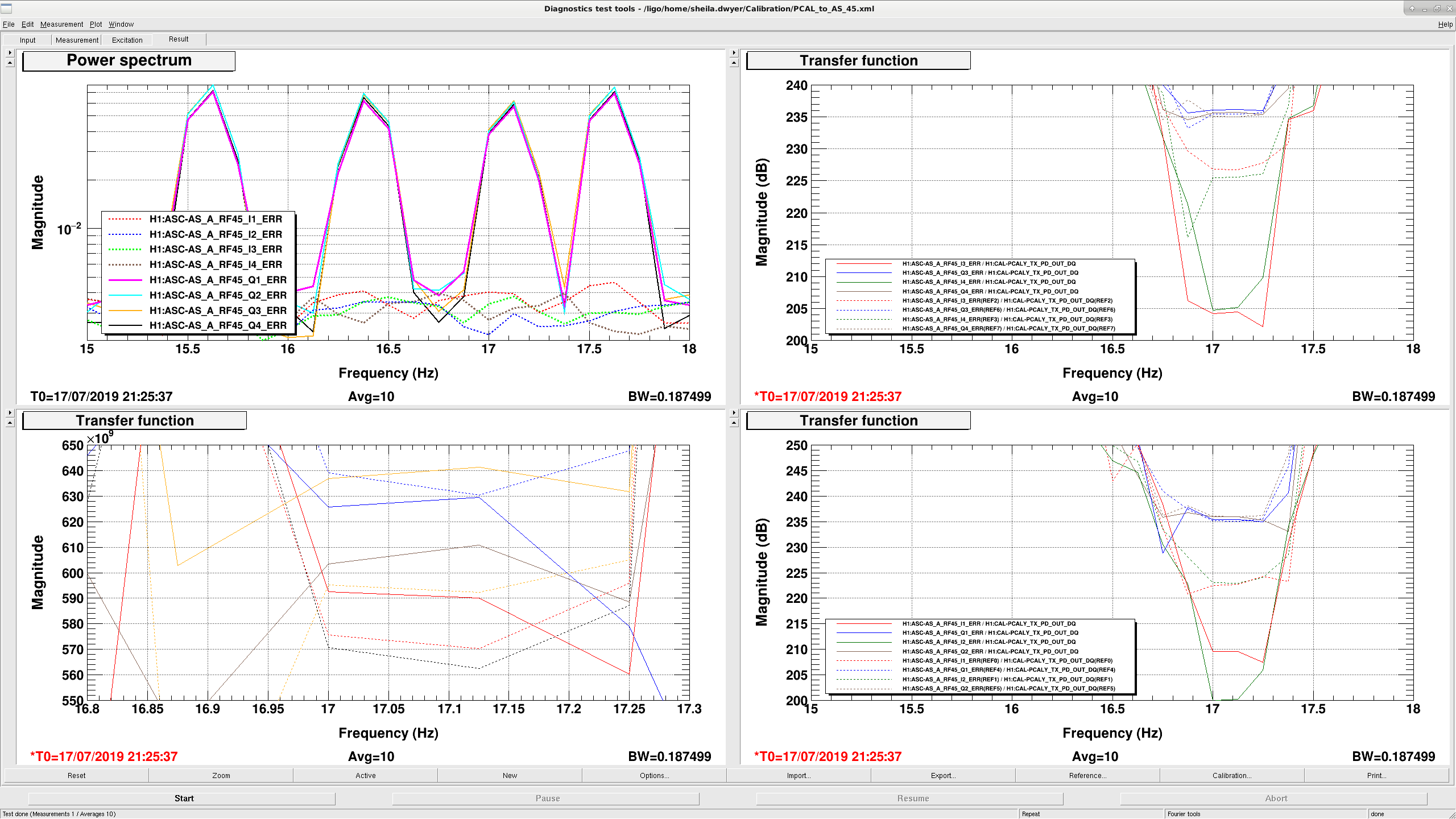
The second screenshot shows how we phased the AS45, the right panels show before transfer functions at the pcal Y line frequency (17.1Hz) before phasing with dashed lines and after with solid lines. The spectrum of the individual quadrants after phasing shows that the calibration lines are now in the Q phase.
A more quantitative statement about how much we reduce the length to angle signals will be added soon....
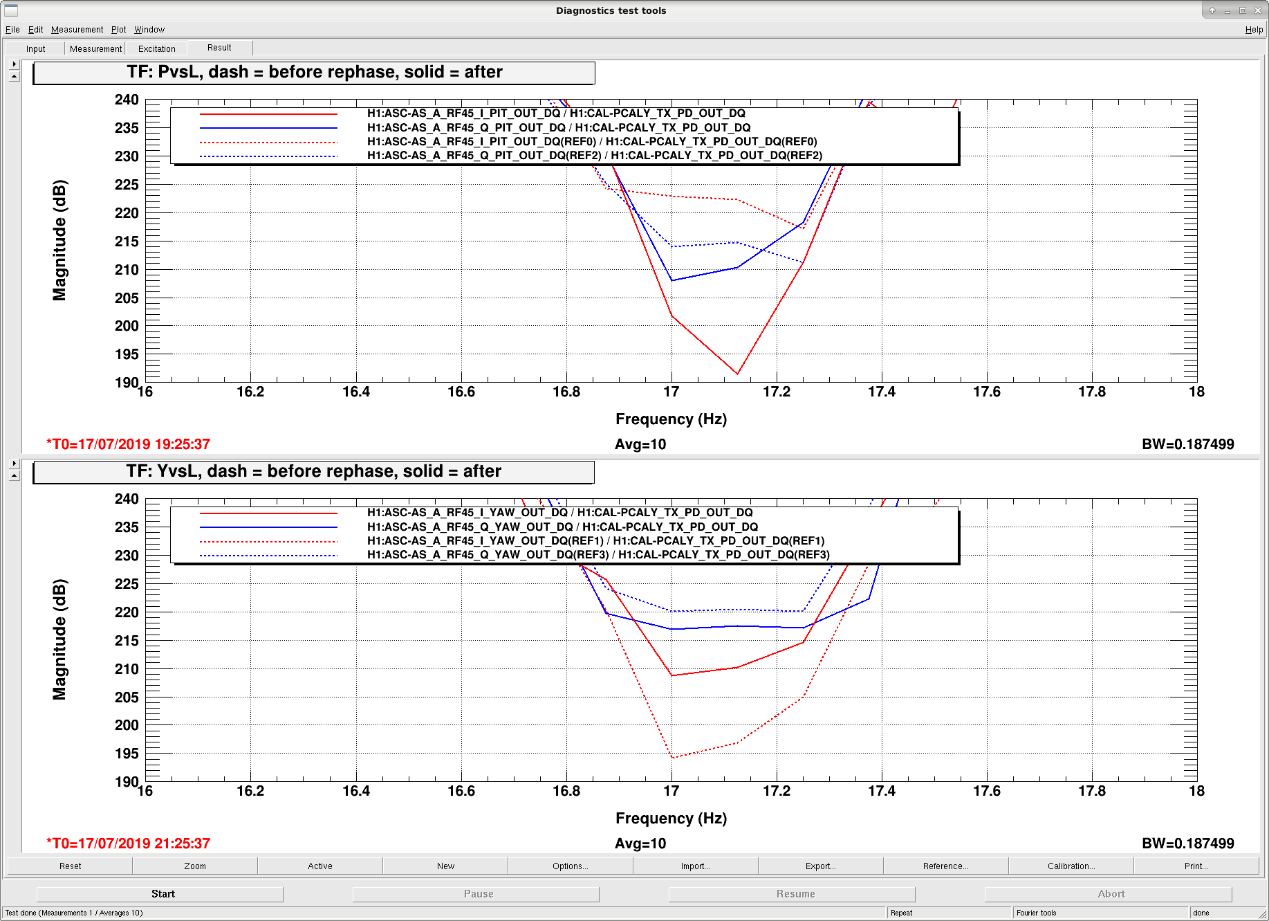
I've finally gotten around to looking at the magnitude of the angular response to the calibration length actuation before and after this AS A rephasing.
In the attached screenshot, the top panel is the AS A RF45 pitch signals versus the Pcal, and the bottom panel is the AS A RF45 yaw signals. Dashed traces are before the rephasing, solid are after. Red traces are the I signals (not used for the IFO), and blue traces are the Q phase which are used for DHARD.
Looking primarily at the blue traces, we see that for a constant length drive (we're assuming that the pcal actuation is (a) constant, and (b) pure length) the Q-phase angular response is lower after we rephased the WFS. However, the ratio isn't very large - we see a 5dB improvement in pitch and only a 3dB improvement in yaw.
Still no improvements for the Y-Arm. Symptoms:
Ideas Tried So Far:
1) Took ITMy, ETMy & TMSy sliders to time before last lock: 1:41utc. NO CHANGE.
2) As an act of desperation, I lowered the polarization from 3 down to 0 for the yarm (and while at it for the xarm from 23 down to 17). NO CHANGE.
3) I'm going to have lunch now.
Ideas to try next:
After this, I will have to leave for the DAY team.
NOTE: This is my first time locking after the Camera Bump. So not sure I'm missing a new trick for locking. Will read through alogs if I think there's any hope.
11:09 Going to CORRECTIVE MAINTENANCE (down since 9:08utc)
Since this isn't the usual locking or aligning, I'm going to mark this down time as CORRECTIVE MAINTENANCE since something is wrong and beyond my normal means.
The algnment of the y-arm was really bad. The strongest mode was a TEM01 mode at 0.7 transmission! The Y-arm locking condition triggers on transmitted power only with a threshold of 0.6. This means the auto-alignment loops were turning on which will result in nothing good when locked on the wrong mode. I also noticed that the y-arm will lock on many bad modes all the times and I lowered the acquire gain from -4 to -20dB.
One thing to be careful when doing the alignment with a free swinging test mass is to make sure that the TEM00 mode gets optimized. The only way to tell is to look at the camera. This is hard while free swinging, since the y-arm experiences a large number of higher order modes. Also be aware there is a delay between the camera image and dataviewer/ndscope.